
Related Manuals for Discovery Telecom XD-1


Summary of Contents for Discovery Telecom XD-1
- Page 1 “Discovery” XD-1 ASSEMBLY INSTRUCTIONS Preliminary Print model pages on 67lb white cover stock. Some pieces require lamination onto 1mm cardboard. A pair of heavy straight-edges such as yardsticks or meter sticks to assemble the spine.
- Page 2 Spine Score and cut out piece 7a. Cut out piece 7* from 24lb paper Form 7a into a Y shape, be sure there is no glue on the triangular tabs. (figure 1) Repeat for 7b except the triangular tabs should be splayed out (see figure 4). Figure 1 Piece 7a completed Figure 2...
- Page 3 Score, cut out and assemble piece 11. (Optional: separate the large end piece from the rest, remove the glue tabs and laminate to 1mm cardboard. Form the main “tube” then insert the end piece from the rear and glue inplace on the inside) Glue the 7b end of the spine to Piece 11 as shown.
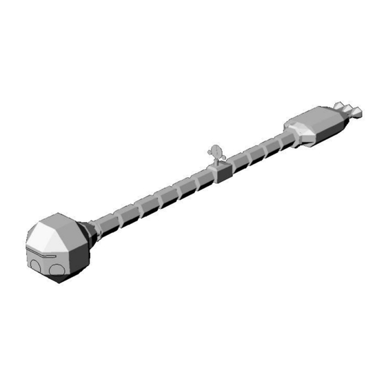
- Page 4 4 fuel modules mounted onto the spine. Note the location of the splice. Figure 8 Assemble the AE-35 module, piece 9. Mount onto the spine; note carefully the orientation of the module. Figure 9 Mount the remaining 6 fuel modules. Vary the orientation of the modules.
- Page 5 Roughly cutout 4d and laminate to a piece of 1mm cardstock. Laminate 4c onto the backside of the same piece. Cutout the Y shaped hole and trim 4c to the final shape. Cut out 4b and glue in place on 4c. Mount onto the spine as shown aligning the surface of 4d with the mark on the spine.
- Page 6 Form the 4 emergency engine tubes, part 3, into cylinders. Attach to part 4 as shown. Figure 14 Command Module Score, cutout, fold and assemble parts 1 and 2. Attach 2 to 1, carefully noting green alignment marks to complete the Command Module.
- Page 7 AE-35 Antenna Form the various parts of the antenna by scoring and cutting around the outer rectangles. Fold over and glue to form 2 sided pieces, then cut out the final shapes. Form the base and cylinder of 10d. Glue 10c into he bottom of 10d then cap 10d.
Need help?
Do you have a question about the XD-1 and is the answer not in the manual?
Questions and answers