Advertisement
Quick Links
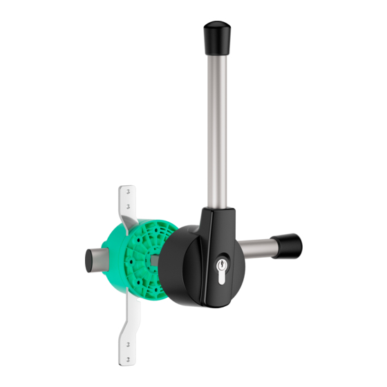
MULTIPLE LOCKING SYSTEM
EURO 5000
3.31.51XX.0
with profi le-cylinder and 3 keys
Date of issue 05/2017 • All specifi cations are approximate • Errors and changes excepted
Product photos are for illustration purposes only
Available options:
• door thicknesses 52 - 60 mm, 72 - 80 mm, 82 - 90 mm, 92 - 100 mm, 102 - 110 mm, 112 - 120 mm, 132 - 140 mm, 152 - 160 mm
• electronic status indicator profi le-cylinder
• electronic status indicator inside handle
• Locking System Euro 5000 single
• Locking System Euro 5000 single with latch
FEATURES
Operation angle
Mounting
Temperature range
Cap
Model
Tested up to
MATERIALS & SURFACE
Housing, Cap
Handle
Gear rack
Inside guide
Outside guide
Conformity of the materials
www.stuv.de
90°
16 x Countersunk screw M5
-40°C up to +80°C
luminescent
right hand and left hand mountable
200.000 cycles
Plastic, dyed
Stainless steel
Stainless steel
Plastic, dyed
Zinc die-casting, plated
all materials used are RoHS and REACH compliant
01
MADE
IN
GERMANY
Advertisement

Related Manuals for Stuv EURO 5000

Summary of Contents for Stuv EURO 5000
- Page 1 • door thicknesses 52 - 60 mm, 72 - 80 mm, 82 - 90 mm, 92 - 100 mm, 102 - 110 mm, 112 - 120 mm, 132 - 140 mm, 152 - 160 mm • electronic status indicator profi le-cylinder • electronic status indicator inside handle GERMANY • Locking System Euro 5000 single • Locking System Euro 5000 single with latch FEATURES Operation angle 90° Mounting...
- Page 2 When changing the profile half cylinder, make sure that the locking lug is in 90° position (3 o‘clock) SAFETY NOTICE For safety reasons a second person must be on the outside of the door when testing the emergency escape function with the door installed www.stuv.de...
- Page 3 Outside handle Gear rack Square shaft Inside guide Outside guide Inside guide Gear rack Pinion Stop bolt Inside handle When changing the profile half cylinder, make sure Figure Z that the locking lug is in 90° position (3 o‘clock) www.stuv.de...
- Page 4 TOLERANCE COMPENSATION 3.31.51XX.0 Washer Hexagon socket screw Tolerance compensation Square shaft Tolerance compensation nose Fig 1 Inside handle Fig 2 Fig 3 Fig 4 Tolerance compensation nose (Pos.10) Inner lever nose (Pos.2) www.stuv.de...
-
Page 5: Drilling Pattern
DRILLING PATTERN 3.31.51XX.0 Door Door Outside Inside Frame Frame Inside Outside Door www.stuv.de... - Page 6 ROD CONNECTION 3.31.51XX.0 Rods not included www.stuv.de...
Need help?
Do you have a question about the EURO 5000 and is the answer not in the manual?
Questions and answers