
Related Manuals for ESD XMC UltraScale+ Zynq XMC-CPU/Zulu

Summary of Contents for ESD XMC UltraScale+ Zynq XMC-CPU/Zulu
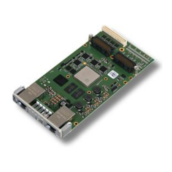
- Page 1 XMC-CPU/Zulu ® XMC UltraScale+ Zynq MPSoC Board with integrated FPGA Hardware Manual to Product V.2031.01 XMC-CPU/Zulu Hardware Manual Doc.-Nr.: V.2031.21 /-Rev 1.0 Page 1 of 45...
- Page 2 design.
- Page 3 Document Information Document file: I:\Texte\Doku\MANUALS\PMC-XMC\XMC-CPU-Zulu\XMC-CPU-Zulu_Hardware-Manual_en_10.docx Date of print: 2021-03-09 Document-type DOC0800 number: Hardware version.: 1.0 Software version: Document History The changes in the document listed below affect changes in the hardware as well as changes in the description of the facts, only. Rev.
- Page 4 Classification of Warning Messages and Safety Instructions This manual contains noticeable descriptions, warning messages and safety instructions, which you must follow to avoid personal injuries or death and property damage. This is the safety alert symbol. It is used to alert you to potential personal injury hazards. Obey all safety messages and instructions that follow this symbol to avoid possible injury or death.
-
Page 5: Safety Instructions
Safety Instructions ● When working with the XMC-CPU/Zulu follow the instructions below and read the manual carefully to protect yourself from injury and the XMC-CPU/Zulu from damage. ● The device is a built-in component. It is essential to ensure that the device is mounted in a way that cannot lead to endangering or injury of persons or damage to objects. - Page 6 It is the responsibility of the device's user to take care that necessary safety precautions for the...
-
Page 7: Table Of Contents
Table of Contents Safety Instructions .......................... 5 1 Overview ............................ 9 1.1 Description of XMC-CPU/Zulu .................... 9 1.2 Glossary ........................... 11 2 PCB View with Connectors ....................... 12 3 LEDs ............................14 3.1 Position of the LEDs ......................14 3.1.1 Position ........................14 3.1.2 Indication of Ethernet LEDs ETH0, ETH1 .............. - Page 8 8.5 Software ........................... 42 8.5.1 Peta Linux ......................42 8.5.2 U-Boot ........................42 8.5.3 Linux ........................43 8.5.4 VHDL-Code ......................43 9 References ..........................43 10 Declaration of Conformity ......................44 11 Order Information ........................45 11.1 Hardware ......................... 45 11.2 Manuals ...........................
-
Page 9: Overview
VxWorks . The BSPs include an example source code for the FPGA. Programming of the FPGA is done via XILINX Toolchain. The esd EtherCAT Master Stack is available for various operating systems. XMC-CPU/Zulu Hardware Manual Doc.-Nr.: V.2031.21/ 1.0 Page 9 of 45... - Page 10 Local Bus Specification 3.0. - Ethernet The rear IO Ethernet signals are connected via P6. To connect standard Ethernet cabling an esd PIM module is available on request. The PIM module comes with an RJ45 connector and the Ethernet transformers on-board.
-
Page 11: Glossary
Overview 1.2 Glossary Abbreviations Abbreviation Term Application Programming Interface Controller Area Network Central Processing Unit CAN in Automation FPGA Field Programmable Gate Array FSBL First Stage Bootloader Hardware Input/Output Least Significant Bit Most Significant Bit n.a. not applicable Operating System Processing System (APUs + Memory + Ethernet etc.) Programmable Logic (FPGA) Real Time Clock... -
Page 12: Pcb View With Connectors
PCB View with Connectors 2 PCB View with Connectors Figure 2: PCB top view The Debug interface (X800) must be connected from the bottom side of the XMC-CPU/Zulu, see Figure 3. PCB Bottom Layer Figure 3: PCB bottom view NOTICE Read chapter “Hardware Installation”... - Page 13 PCB View with Connectors See also from page 28 for signal assignment of the CAN connectors. For a description of the DIP switch and the SMD tactile switches see page 17. The LEDs are described in chapter “LEDs ” page 14. XMC-CPU/Zulu Hardware Manual Doc.-Nr.: V.2031.21/ 1.0 Page 13 of 45...
-
Page 14: Leds
LEDs 3 LEDs 3.1 Position of the LEDs 3.1.1 Position Figure 4: Connectors and LEDs 3.1.2 Indication of Ethernet LEDs ETH0, ETH1 The Activity and Link/Speed LEDs are integrated in the RJ45 sockets of ETH0 and ETH1 and display the status of the corresponding ETH channel. Indicator Colour Function... -
Page 15: Leds On Pcb
LEDs 3.2 LEDs on PCB Figure 5: Connectors and LEDs 3.2.1 Ethernet LEDs The 8 green LEDs (Speed, Activity and Link) are equipped on the bottom side of the XMC-CPU/Zulu see Figure 5. LED name Zynq Name Function Display Meaning LED on in schematic Section diagram... -
Page 16: Other Leds
LEDs 3.2.2 Other LEDs The LEDs are equipped on the rear side of the XMC-CPU/Zulu, see Figure 5. LED name in Colour Function Display Description (LED on) schematic diagram Transmitting data of serial interface via green SER0_Tx flashing LED410 USB port CON Receiving data of serial interface via port green SER0_RX flashing... -
Page 17: Hardware Configuration
Hardware Configuration 4 Hardware Configuration 4.1 Coding Switch and Reset Buttons The DIP-switch MODE and the 3 SMD tactile switches PROG, SRST and POR are equipped on the bottom layer of the XMC-CPU/Zulu. See Figure 3 on page 12 for the position on the PCB. Figure 6: Position of the switches (detail) 4.1.1 Mode The DIP-switch MODE (PS_MODE) comes with 4 Mode pins. -
Page 18: Prog, Srst, Por
Hardware Configuration 4.1.2 PROG, SRST, POR The XMC-CPU/Zulu comes with the 3 reset buttons (SMD tactile switches): PROG, SRST and POR, see Figure 6, page 17. For further information about the reset signals see Technical Reference Manual of the Zynq UltraScale+ Device [1]. Reset Direction Description... -
Page 19: Hardware Installation
Hardware Installation 5 Hardware Installation NOTICE Read the safety instructions at the beginning of this document carefully before you start with the hardware installation! WARNING Hazardous Voltage - Risk of electric shock due to unintentional contact with uninsulated live parts with high voltages inside of the system into which the XMC-CPU/Zulu is to be integrated. - Page 20 Hardware Installation Remove your carrier board (if already installed) and plug the XMC-CPU/Zulu carefully on the carrier board. Pay attention that the XMC-CPU/Zulu is correctly installed on the carrier board. NOTICE Please note that the number of mating cycles of the XMC connectors P5 and P6 is only 10! Do not uninstall the XMC-CPU/Zulu from the carrier board if it is not absolutely necessary! Fix the XMC-CPU/Zulu with the screws on the carrier board.
-
Page 21: Technical Data
Technical Data 6 Technical Data 6.1.1 General Technical Data Nominal voltage: 3.3 V / I = 640 mA, = 610 mA 3.3V_MAX 3.3V_TYPICAL VPWR: Power supply = 830 mA, = 720 mA 5V_MAX 5V_TYPICAL voltage = 400 mA, = 340 mA 12V_MAX 12V_TYPICAL Absolute maximum power: P... -
Page 22: Cpu Kernel
Technical Data 6.2 CPU Kernel Dual Core A53 Application Processor Unit (APU) Architecture + Dual Core Real-time Processor Unit. XILINX Zynq UltraScale+ CG XCZU2CG-1SFVA625E – 2x APU, 2x RPU 1.3 GHz APU, Clock rate 533 MHz RPU Internal FPGA resources: Programmable 103K System Logic Cells, Logics... -
Page 23: Ethernet Interface Ps
Technical Data 6.3 Ethernet Interface PS Number of Ethernet interfaces Standard IEEE 802.3, 10BASE-T, 100BASE-TX, 1000BASE-T Bit rate 10/100/1000 Mbit/s Controller integrated in the PS (Processing System) section of the CPU Connection Twisted Pair (compatible with IEEE 802.3), 1000BASE-T, 1x via transformer integrated in the RJ45 socket Electrical isolation electrical strength 1500V AC / 60sec 1 x without electrical isolation... -
Page 24: Usb Console Port (Con)
Technical Data 6.5 USB Console Port (CON) Number 1 asynchronous serial interface, used as terminal interface Controller integrated in CPU Value range: 9600 Baud ... 115200 Baud Bit rate Default setting: 115200 Baud, 8 Bit, No Parity 1 Stop-Bit UART serial console transformed to USB 1.1 Physical Interface via USB to serial converter Software... -
Page 25: Digital Inputs/Outputs P4
Technical Data 6.7 Digital Inputs/Outputs P4 Number Maximum 62, see chapter “PMC P4 I/O Connector” page 30 for assignment IO Configuration Single ended or differential inputs or outputs, depending on FPGA pin configuration. Routed as differential pair in the layout Physical interface 1.8V to 3.3V level shifters or FET switches for LVDS signals can be alternatively enabled per Enable PIN... -
Page 26: Control Elements And Display Elements
Technical Data 6.9 Control Elements and Display Elements LEDs 5 tricolour LEDs. Control via I²C bus – the controller is optionally in the PL or PS section of the CPU, mechanical design via LED Riser card and light pipes. Buttons 3 SMD tactile switches for the signals SRST, PROG and POR (Power On Reset) are equipped on the bottom layer of the XMC-CPU/Zulu (see Figure 6 page 17). -
Page 27: Microsd Card Slot
Technical Data 6.12 MicroSD Card Slot Number Standard Compatible with the SD Host Controller Specification revision 3.0 (SDHC) Topology Directly connected to the CPU Controller Integrated into the PS section of the CPU Data rate SDR104 mode (theoretically 800Mbyte/s) Supported media The usability of individual media (manufacturer, type, size) depends on the technology used and can not be granted. -
Page 28: Connector Assignments
Connector Assignments 7 Connector Assignments 7.1 PMC/XMC Connectors 7.1.1 PMC P1 Connector Signal Signal -12V INTA# INTB# INTC# GND (PRESENT#) INTD# n.c. (reserved) n.c. (reserved) PCI-CLK GNT# REQ# AD[31] AD[28] AD[27] AD[25] C/BE3# AD[22] AD[21] AD[19] AD[17] FRAME# IRDY# DEVSEL# n.c. -
Page 29: Pmc P2 Connector
Connector Assignments 7.1.2 PMC P2 Connector Signal Signal +12V TRST# n.c. (reserved) n.c. (reserved) n.c. (reserved) MODE2# +3.3V PCI-RST# MODE3# +3.3V MODE4# n.c. (PME#) AD[30] AD[29] AD[26] AD[24] +3.3V IDSEL AD[23] +3.3V AD[20] AD[18] AD[16] C/BE2# IDSELB TRDY# +3.3V STOP# PERR# +3.3V SERR#... -
Page 30: Pmc P4 I/O Connector
Connector Assignments 7.1.3 PMC P4 I/O Connector Signal Alternative Notes Differential Pair (XILINX Name) Notes Name Signal Name FPGA-IO<0> 3.3V, IO IO_L20N_T3L_N3_AD1N_66 FPGA-IO<1> 3.3V, IO IO_L23N_T3U_N9_66 FPGA-IO<2> 3.3V, IO IO_L20P_T3L_N2_AD1P_66 FPGA-IO<3> 3.3V, IO IO_L23P_T3U_N8_66 FPGA-IO<4> 3.3V, IO IO_L21N_T3L_N5_AD8N_66 FPGA-IO<5> 3.3V, IO IO_L24N_T3U_N11_PERSTN0_65 FPGA-IO<6>... - Page 31 Connector Assignments Signal Alternative Notes Notes Notes Differential Pair (XILINX Name) Name Signal Name FPGA-IO<32> 3.3V, IO IO_L6N_T0U_N11_AD6N_64 FPGA-IO<33> 3.3V, IO CAN0_TX 3.3V, O IO_L17N_T2U_N9_AD10N_65 FPGA-IO<34> 3.3V, IO IO_L6P_T0U_N10_AD6P_64 FPGA-IO<35> 3.3V, IO CAN0_RX 5V, I IO_L17P_T2U_N8_AD10P_65 FPGA-IO<36> 3.3V, IO IO_L12N_T1U_N11_GC_64 CLK Input FPGA-IO<37>...
-
Page 32: Xmc - P5
Connector Assignments 7.1.4 XMC - P5 Signal / PIN Signal / PIN Signal / PIN Signal / PIN Signal / PIN Signal / PIN Row A Row B Row C Row D Row E Row F PCIe_Tx_L0p PCIe_Tx_L0n 3.3V PCIe_Tx_L1p PCIe_Tx_L1n unused unused... -
Page 33: Xmc - P6 I/O Connector
Connector Assignments 7.1.5 XMC – P6 I/O Connector Signal / PIN Signal / PIN Signal / PIN Signal / PIN Signal / PIN Signal / PIN Row A Row B Row C Row D Row E Row F ETH1-MDIO0_P 1 ETH1-MDIO0_N 1 ETH1-MDIO1_N 1 ETH1-MDIO2_P 1 ETH1-MDIO2_N... -
Page 34: Ethernet Eth0, Eth1
Cables of category CAT 5e or higher must be used to grant the function in networks with up to 1000 Mbits/s. esd grants the EC conformity of the product if the wiring is carried out with shielded twisted pair cables of class SF/UTP or higher. -
Page 35: Usb Console Port - Con (X1220)
Connector Assignments 7.3 USB Console Port – CON (X1220) Device connector: 5-pin mini USB socket, standard type B Pin Position: Pin Assignment: (X1220) (Input) Signal Description VBUS... +5 V power supply voltage D+, D-... USB signal lines Data+, Data- -... not connected GND... -
Page 36: Adapters
XILINX ChipScope to the XMC-CPU/Zulu connector X1410. NOTICE The connector X400 is for factory test only, do not connect! The adapter can be used by esd to connect X400 to a JTAG chain of the Health Controller and PCIe-to-PCI bridge. Samtec CLM <->... -
Page 37: Xmc-Jtag-Adapter
Connector Assignments 7.4.2 XMC-JTAG-Adapter The XMC-JTAG-Adapter (esd order No.: V.2031.04) is an adapter cable to connect the JTAG- Interface onboard with the programmer (XMC-CPU/Zulu-Testadapter, esd order No.: V.2031.05). The adapter comes with a header on one side and a socket strip on the other side. -
Page 38: Figure 11: Connecting Diagram Of The Xmc-Jtag-Adapter
Connector Assignments Connecting the XMC-CPU/Zulu-Testadapter to the XMC-CPU/Zulu via XMC-JTAG-Adapter Figure 11: Connecting diagram of the XMC-JTAG-Adapter Page 38 of 45 Hardware Manual Doc.-Nr.: V.2031.21 /Rev. 1.0 XMC-CPU/Zulu... -
Page 39: Software
For the FPGA an esdACC (esd Advanced CAN Controller) implementation is available as customized option. The esd EtherCAT Master is available for the BSPs developed by esd (see page 45). For detailed information about the driver availability for your operating system, please contact our sales team: sales@esd.eu... -
Page 40: Licenses
This product uses the open source-bootloader “Das U- Boot”. The U- Boot-source code is released under the terms of the GNU Public License (GPL). The complete text of the license is contained in the esd-document “3rd Party Licensor Notice” as part of the product documentation. License information esd provides the complete bootloader-source code on request. -
Page 41: Generating Firmware Image
R5 CPUs which are also contained in the system. A Boot-Image (BOOT.BIN) which is created with the toolchain usually contains the following components. esd electronics assumes only a limited warranty for the necessary adjustments to the components in the scope of this project. -
Page 42: Software
Software 8.5 Software 8.5.1 Peta Linux The Xilinx Peta Linux version v2018.2 is used as base for the development of Linux. The Standard Linux is created by means of the development environment. By means of Yocto the software adaption for the XMC-CPU/Zulu is integrated. A combination of single modules built the firmware image. -
Page 43: Linux
A dynamic change of the Monarch / Root status is not supported. It is possible to request the Monarch / Root status of U-Boot. Customized Options: esd IP-Core (esdACC) RTC is used by Linux 8.5.4 VHDL-Code To verify the functionality of the periphery an FPGA implementation is created that allows a... -
Page 44: Declaration Of Conformity
Declaration of Conformity 10 Declaration of Conformity Page 44 of 45 Hardware Manual Doc.-Nr.: V.2031.21 /Rev. 1.0 XMC-CPU/Zulu... -
Page 45: Order Information
Hardware manual in English Table 23: Available Manuals Printed Manuals If you need a printout of the manual additionally, please contact our sales team (sales@esd.eu) for a quotation. Printed manuals may be ordered for a fee. XMC-CPU/Zulu Hardware Manual Doc.-Nr.: V.2031.21/ 1.0...
Need help?
Do you have a question about the XMC UltraScale+ Zynq XMC-CPU/Zulu and is the answer not in the manual?
Questions and answers