Table of Contents
Advertisement
Quick Links
EPPC-T10
®
Embedded 64-bit PowerPC
T1014
Single Board Computer
Hardware Manual
to Product I.2007.02
EPPC-T10
Hardware Manual • Doc. No.: I.2007.21 / Rev. 1.1
Page 1 of 37
esd electronics gmbh
Vahrenwalder Str. 207 • 30165 Hannover • Germany
http://www.esd.eu
Phone: +49 (0) 511 3 72 98-0 • Fax: +49 (0) 511 3 72 98-68
Advertisement
Table of Contents

Subscribe to Our Youtube Channel
Related Manuals for ESD EPPC-T10

Summary of Contents for ESD EPPC-T10
- Page 1 EPPC-T10 Hardware Manual • Doc. No.: I.2007.21 / Rev. 1.1 Page 1 of 37 esd electronics gmbh Vahrenwalder Str. 207 • 30165 Hannover • Germany http://www.esd.eu Phone: +49 (0) 511 3 72 98-0 • Fax: +49 (0) 511 3 72 98-68...
- Page 2 design.
- Page 3 Document file: I:\Texte\Doku\MANUALS\Embedded\EPPC-T10\EPPC-T10-Manual_en_11.odt Date of print: 2019-05-07 Document type DOC0800 number: Hardware version: PCB Rev.1.1 Document History The changes in the document listed below affect changes in the hardware as well as changes in the description of the facts, only.
- Page 4 This NOTICE statement contains the general mandatory sign and gives information that must be heeded and complied with for a safe use. INFORMATION INFORMATION Notes to point out something important or useful. Page 4 of 37 Hardware Manual • Doc. No.: I.2007.21 / Rev. 1.1 EPPC-T10...
-
Page 5: Safety Instructions
● The EPPC-T10 may become warm during normal use. Always allow adequate ventilation around the EPPC-T10 and use care when handling. ● Do not operate the EPPC-T10 adjacent to heat sources and do not expose it to unnecessary thermal radiation. Ensure an ambient temperature as specified in the technical data. - Page 6 It is the responsibility of the device's user to take care that necessary safety precautions for the device's network interface are in place.
-
Page 7: Table Of Contents
Kernel.......................... 11 Memory - Interface....................... 12 Real Time Clock (RTC)......................12 Boot – ROM......................... 12 2.7 EEPROM..........................12 2.8 Connectors.......................... 13 2.8.1 Connectors in the EPPC-T10 Enclosure..............13 2.8.2 Connectors on the Main Board (internal)..............13 Ethernet Interfaces....................... 14 2.10 Serial Interface........................14 2.11... - Page 8 SATA- Power 0 (X2001)....................34 8.6.3 Backup-Battery and Front LEDs, JTAG...............35 8.6.3.1 Backup-Battery and Front LEDs (X180) ...............35 8.6.3.2 JTAG CPU (X800) ....................35 9. Conformity..........................36 Order Information........................37 Page 8 of 37 Hardware Manual • Doc. No.: I.2007.21 / Rev. 1.1 EPPC-T10...
-
Page 9: Overview
16 Mbyte SPI Flash for boot loader and 32 Kbit I²C EEPROM for U-Boot environment offer non- volatile memory spaces. The EPPC-T10 features a second 16 Mbyte 'fallback' SPI Flash, used for system recovery if a system crash occurs during a firmware update. Alternatively it can be used for application software. - Page 10 Please contact our sales team for detailed information. Customized options are for example: - CPU Type The EPPC-T10 is also available with the power saving dual-core QorlQ CPU T1022 or with the quad-core QorlQ CPU T1042 on request. - Memory The memory can be extended with larger DDR3 RAM and Flash.
-
Page 11: Technical Data
2x8 Pin connector, 2.54 mm pitch, with IEEE1149.1 (JTAG) With signals for: - Manufacturing test (Boundary Scan) - Software-Debugging (i.e. ABATRON Debugger) - Initial programming of the serial Boot Flash (U-Boot) EPPC-T10 Hardware Manual • Doc. No.: I.2007.21 / Rev. 1.1 Page 11 of 37... -
Page 12: Memory - Interface
Operating mode Fast (400KHz) I C protocol Content - Serial number of the board - MAC addresses - U-Boot environment - SPD data of the DDR-RAM Page 12 of 37 Hardware Manual • Doc. No.: I.2007.21 / Rev. 1.1 EPPC-T10... -
Page 13: Connectors
Technical Data 2.8 Connectors 2.8.1 Connectors in the EPPC-T10 Enclosure Name Function Type Label X711 RS-232 Serial 1 (RS-232) RJ45 socket without LEDs X100 24 V Power supply voltage Phoenix-Contact MC1,5/3-GF-3,81 X1300 ETH1 Ethernet 1 RJ45 socket with integrated LEDs... -
Page 14: Ethernet Interfaces
Cables of category CAT5e or higher have to be used to grant the function in networks with 1000 Mbit/s. esd grants the EC conformity of the product if the wiring is carried out with shielded twisted pair cables of category CAT5e or higher. -
Page 15: Usb - Host Interface
By means of 12-bit ADC which is connected via I²C to the CPU and possibly required circuits for signal conditioning. Monitoring of - Voltage supply - Battery voltage (RTC) - 3.3 V, 5 V, core voltages EPPC-T10 Hardware Manual • Doc. No.: I.2007.21 / Rev. 1.1 Page 15 of 37... -
Page 16: Pcb View With Connectors
Read chapter “Hardware Installation and Change of Battery” on page 20, before you start with the installation of the hardware! See also page 30 for signal assignment of the connectors. Page 16 of 37 Hardware Manual • Doc. No.: I.2007.21 / Rev. 1.1 EPPC-T10... -
Page 17: Eppc-T10 View
EPPC-T10 View 4. EPPC-T10 View 4.1 Operating position Figure 3: EPPC-T10 mounted on the mounting hat rail See also page 30 for signal assignment of the connectors. NOTICE Read chapter “Hardware Installation and Change of Battery” on page 20, before you start... -
Page 18: Front Side With Leds, Terminal Interface And Sd-Card Slot
EPPC-T10 View 4.2 Front Side with LEDs, Terminal Interface and SD-Card Slot Figure 4: LEDs and connectors in the front panel 4.2.1 LEDs in the Front Panel LED name in Colour Meaning (LED on) schematic diagram Term Green Traffic on Terminal interface... -
Page 19: Front View Upper Side With Serial Interface
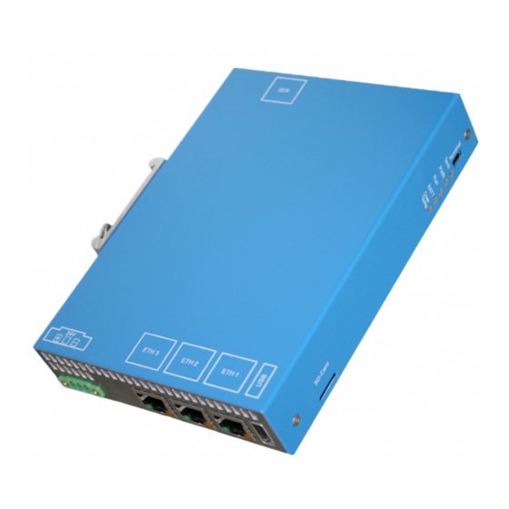
EPPC-T10 View 4.3 Front View Upper Side with Serial Interface Figure 5: Front panel on upper side 4.4 Front View Bottom Side with Ethernet, USB and 24V-Power Supply Figure 6: Front panel on bottom side 4.4.1 Ethernet LEDs The Ethernet LEDs are integrated in the RJ45 sockets of the Ethernet interfaces (ETH1, ETH2 or ETH3). -
Page 20: Hardware Installation And Change Of Battery
If necessary configure the hardware (dip switches or jumper) before you start with the installation. See chapter “Prepare Configuration (DIP-Switches, JP800)” page 23. Make sure that no risk arises from the system into which the EPPC-T10 shall be inserted. DANGER... -
Page 21: Demounting
Hardware Installation and Change of Battery 5.2 Demounting Procedure A1. Switch off the 24 V supply voltage of the EPPC-T10 and if necessary other network participants. A2. Disconnect all connectors (24V, ETH, SER, USB). DANGER Hazardous Voltage Risk of electric shock due to unintentional contact with uninsulated live parts with high voltages. -
Page 22: Change Of Battery
Loosen the 2 screws of the top hat rail mounting clamp (use Torx T20 screw driver). Loosen the 4 screws in the EPPC-T10 case (2 in the back panel and 2 in the front panel; use Torx T10 screw driver). -
Page 23: Prepare Configuration (Dip-Switches, Jp800)
Loosen the 2 screws of the top hat rail mounting clamp (use Torx T20 screw driver). Loosen the 4 screws in the EPPC-T10 case (2 in the back panel and 2 in the front panel; use Torx T10 screw driver). -
Page 24: Configuration Via Dip Switch
Jumper JP180 Meaning Jumper set Switch to second Flash with „Fallback“ Firmware Jumper not set Fail Save Mechanism disabled Figure 9: Jumper internal (Detail) Table 4: Jumper JP180 Page 24 of 37 Hardware Manual • Doc. No.: I.2007.21 / Rev. 1.1 EPPC-T10... -
Page 25: Software Support
Hardware Installation and Change of Battery 5.6 Software Support The flash memory carries the standard boot program “Das U-Boot” and enables the EPPC-T10 to boot various operating systems from on-board Flash, network, USB, microSD card or optional SSD. BSP is available for Linux. Others on request. -
Page 26: Software
6.1 Configuration and Console Access Use an USB cable with miniUSB connector (Terminal interface, see EPPC-T10 front panel, page 18) to connect the EPPC-T10 to a PCs USB port. Install the driver if necessary. Current drivers can be downloaded from :http://www.ftdichip.com/. -
Page 27: Firmware Configuration
The configuration of the bootloader is stored in the so called environment variables. Enter the command printenv for a listing of all environment variables. The following output contains the complete environment of the EPPC-T10 unit in the state of delivery:... -
Page 28: Update Of The Bootloader
TFTP server from which the boot images are loaded serial# Serial number of the EPPC-T10; with name and individual serial number from AA000001, e.g.: EPPC-CPU-T10_AA000001 bootcmd This variable contains the commands that trigger the real boot procedure of the operating system (e.g. -
Page 29: Cpu
7.2 Watchdog The watchdog is described in the manual: “EREF: A Programmer’s Reference Manual for Freescale Embedded Processors”. The manual can be downloaded from the NXP website. EPPC-T10 Hardware Manual • Doc. No.: I.2007.21 / Rev. 1.1 Page 29 of 37... -
Page 30: Connector Assignments
NOTICE For the serial interface shielded cables have to be used. esd grants the EC conformity of the product if the wiring is carried out with a shielded cable with a maximum wire length of 30 m. Page 30 of 37 Hardware Manual •... -
Page 31: Ethernet Eth1 - 3 (X1300, X1400, X1500)
Cables of category CAT5e or higher have to be used to grant the function in networks with 1000 Mbit/s. esd grants the EC conformity of the product if the wiring is carried out with shielded twisted pair cables of category CAT5e or higher. -
Page 32: Usb (X1200)
Connector type: Mini-USB socket type-B, in the case, front panel (see page 18) Pin Position: Position Signal USB - PWR+ Data - Data + USB - PWR- Page 32 of 37 Hardware Manual • Doc. No.: I.2007.21 / Rev. 1.1 EPPC-T10... -
Page 33: Power Supply Voltage (X100)
8.5 24V Power Supply Voltage (X100) DANGER The EPPC-T10 may only be driven by power supply current circuits, that are contact protected. A power supply, that provides a safety extra-low voltage (SELV) according to EN 60950-1, complies with this conditions. -
Page 34: Internal Connectors
Connector Assignments 8.6 Internal Connectors The internal connectors are inside of the EPPC-T10 and are only accessible with case opened. 8.6.1 SATA 0 (X2000) Connector type: 7-pin SATA connector socket Pin Position: Position Signal TX Data + (out) TX Data - (out) -
Page 35: Backup-Battery And Front Leds, Jtag
8.6.3 Backup-Battery and Front LEDs, JTAG NOTICE Do not connect! These connectors are for esd internal use only. The internal connectors are inside of the EPPC-T10 and are only accessible with case opened. 8.6.3.1 Backup-Battery and Front LEDs (X180) Position Signal... -
Page 36: Conformity
Conformity 9. Conformity Page 36 of 37 Hardware Manual • Doc. No.: I.2007.21 / Rev. 1.1 EPPC-T10... -
Page 37: Order Information
This bundle can be extended with additional project licences Table 7: Order information PDF Manuals For availability of English manuals see table below. Please download the manuals as PDF documents from our esd website www.esd.eu for free. Manuals Order No.
Need help?
Do you have a question about the EPPC-T10 and is the answer not in the manual?
Questions and answers