
Related Manuals for Azkoyen U3


Summary of Contents for Azkoyen U3
- Page 1 Azkoyen S.A. Avda. San Silvestre, s/n 31350 Peralta (Navarra) Spain T +34 948 709 709 www.azkoyenpayment.com U3 HOPPER Technical information...
- Page 2 The use of our products, accessories and tools outside the specifications that are described in the manual will be the sole responsibility of the user and under no circumstance will Azkoyen S.A. be held responsible for incorrect or unspecified use.
- Page 3 REVISION HISTORY Date Version Event 01.12.2019 Creation of the document U3 HOPPER – TECHNICAL INFORMATION 01/12/2019...
-
Page 4: Table Of Contents
Contents INTRODUCTION ........................1 GENERAL DESCRIPTION ......................1 2.1. CAPACITY OF THE U3 HOPPER................... 2 2.2. RANGE OF COINS ....................... 2 2.3. DETECTING FULLNESS AND EMPTINESS ................3 2.4. PAYOUT SPEED ........................4 2.5. COMMUNICATION PROTOCOL ..................4 2.6. IN-LINE CONFIGURATION ....................4 2.7. - Page 5 Figure 1 - Level sensor positions....................3 Figure 2 - Configuration of the U3 Hopper in line................. 4 Figure 3 - Position of the bases of two Hoppers U3 in line............5 Figure 4 - Dimensions of the U3 Hopper ..................7 Figure 5 - Dimensions of U3 Hopper with overflow ..............
- Page 6 Table 5 - Current draw ........................6 Table 6 - Dimensions of U3 Hopper ....................7 Table 7 - Dimensions of U3 Hopper with overflow ............... 8 Table 8 - United power pinout ...................... 9 Table 9 - Separated power pinout....................9 Table 10 - Components of the U3 Hopper ..................
-
Page 7: Introduction
- U3 Hopper ccTalk. - U3 Hopper MDB. The U3 Hopper is the result of development to incorporate new security features for the most demanding environments. This device is 100% compatible with the previous U-II Hopper model and maintains all its key features such as reliability, versatility, speed, accuracy and minimal maintenance. -
Page 8: Capacity Of The U3 Hopper
Table 2 - Bowl capacity for Euro 2.2. RANGE OF COINS The multicoin extraction system of the U3 Hopper, guarantees the pay-out of round coins without holes whose dimensions are within the range of diameter and thickness specified. The range of coins accepted depends on the type of disk used. -
Page 9: Detecting Fullness And Emptiness
Only EURO coin range has been tested. For other coin denominations please contact the sales area manager or after sales department. 2.3. DETECTING FULLNESS AND EMPTINESS The U3 Hopper has the option to incorporate detection mechanisms to detect the storage level of the coins in the bowl. •... -
Page 10: Payout Speed
2.4. PAYOUT SPEED The U3 Hopper pays out up to 6.3 coins per second. This speed varies with the different disks used. Cavities of the disk Speed 5.2 coins / second 6.3 coins / second Table 4 - Pay-out speed per disk 2.5. -
Page 11: Anti-Jam And Anti-Span Systems
Figure 3 - Position of the bases of two Hoppers U3 in line. NOTE: The bases of U3 Hopper and U-II Hopper are 100% compatible. 2.7. ANTI-JAM AND ANTI-SPAN SYSTEMS • Jam: The hopper has a current draw detector that, when there is a coin jam, reverses the spin direction of the disk motor to free the jammed coins. -
Page 12: Technical Characteristics
Optimum results from using this equipment can be obtained by meeting the following requirements: Temperature range: ■ Working temperature: +5 ºC to +55 ºC. ■ Storage temperature: -25 ºC to +70 ºC. Maximum inclination: +/- 3º on all axes. U3 HOPPER – TECHNICAL INFORMATION... -
Page 13: Parameter Of Quality
3.4. PARAMETER OF QUALITY Lifespan: 2.000.000 extracted coins. MCBF: 1.000.000 extracted coins. 3.5. DIMENSIONS • Hopper bowls Figure 4 - Dimensions of the U3 Hopper Bowl type Length (L) Width Height * 119.7 mm 127 mm 152 mm... -
Page 14: Figure 5 - Dimensions Of U3 Hopper With Overflow
• Hopper bowl with overflow Figure 5 - Dimensions of U3 Hopper with overflow Bowl type Length (L) Overflow 154 mm Tolerance of ±1mm Table 7 - Dimensions of U3 Hopper with overflow U3 HOPPER – TECHNICAL INFORMATION... -
Page 15: Electrical Diagrams And Pinout
3.6. ELECTRICAL DIAGRAMS AND PINOUT The U3 Hopper uses a type 5 connector indicated by the ccTalk general specification. It is a 10- pin connector (2x5) of 2.5mm pitch, Molex 8624 or similar. The U3 Hopper has two different connecting versions depending on the part number of the product: united or separated power. -
Page 16: Figure 8 - General Diagram For Power Separated Hoppers
GND_POWER and GND_LOGIC, due to the voltage drop along the cables, of up to ±2.5 Volts. Even though the new feature of separating the power requires a pinout of the U3 Hopper, which differs from its predecessor U-II Hopper, it is still compatible. -
Page 17: Description Of Components
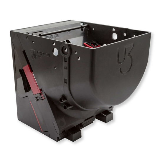
4.1. COIN BOWL The coin bowl is where the U3 Hopper stores the coins and, is also from where they are extracted when ordered to do so by the machine. Its design allows to be stored the maximum number of coins in the minimum space, considering that even the last coin can be extracted. -
Page 18: Table 11 - Bowl Components Of U3 Hopper
Bowl components and sizes of U3 Hopper Hopper size Small Medium M Large Extra-large XL Overflow O Bowl base Bowl extension Disk cavities Normal flap Blade 1.5 Large flap Short blade Table 11 - Bowl components of U3 Hopper U3 HOPPER – TECHNICAL INFORMATION... -
Page 19: Moving Flap
(12 slots disk) Figure 10 - Types of flaps 4.3. COIN LEVEL DETECTORS The U3 Hopper has the option to incorporate optic detectors to detect the level of coins stored into the bowl. • Bottom level detection Bottom detection is carried out by a photocell (photodiode and phototransistor) that is located in the holes at the bottom of the coin bowl. -
Page 20: Blade
For 5 cents to 2 € coins Blade 1.5 Short blade 1.7 mm – 3.2 mm 12 mm – 20 mm Table 12 - Coin dimensions * To use the hopper with thinner coins please contact Azkoyen. U3 HOPPER – TECHNICAL INFORMATION... -
Page 21: Trigger
In the coin extraction process this device compresses the trigger spring and at a certain point it ejects the coin out from the hopper. The U3 Hopper has only one type of trigger, made of plastic. Figure 12 - Trigger 4.6. -
Page 22: Configuration Switches
Table 13 - Electronic board components 4.6.1.1. CONFIGURATION SWITCHES The configuration of the address of the U3 Hopper, as with other functions, is done with the dipswitches. The 8 switches located on the board are accessible from the underside of the hopper as shown in the illustration. -
Page 23: Table 15 - Addresses For Switch Combinations
With the switches 1, 2, 3 and 4 up to 16 U3 Hoppers can be addressed, as indicated in the following table: ccTalk address Table 15 - Addresses for switch combinations Switch 5 is not used. Switch 6 is used to select the address of the U3 Hopper; the address can be selected by... -
Page 24: Cctalk Connector
(Molex 8624 Series). It is connected to ribbon cable of 10-way type Molex 40312 Series MX50. ccTalk connector * Separated power United power Function Function DATA DATA GND_POWER GND_POWER VDC_POWER VDC_LOGIC GND_LOGIC VDC_POWER Table 18 - ccTalk connector for separated / united power * For MDB connector ask Azkoyen U3 HOPPER – TECHNICAL INFORMATION... -
Page 25: Connector For Azkoyen Tools
4.6.1.3. CONNECTOR FOR AZKOYEN TOOLS This connector is used to communicate with Azkoyen programming tools. (See chapter 5.1 TL20 AND HEUS) The pinout of the connector is the following: Azkoyen tools connector Function Table 19 - Pinout connector for Azkoyen tools 4.7. -
Page 26: Motor And Blocking System
The motor spins the disk, which results on the coins leave from the coin bowl. The U3 Hopper uses a motor of 12 V that can be powered from 12V to 24V (± 10 %). See point 3.2 CURRENT DRAW for electrical characteristics. -
Page 27: Infrared Photocells For Coin Counting
This is an accessory that is used to attach the hopper to the machine. It has holes to fix it to the machine and with clips to hold the hopper. The base of the U-II Hopper U-II is totally compatible with the U3 Hopper. ref.: 11036721 Figure 17 - Hopper base U3 HOPPER –... -
Page 28: Disk Support
This component also has guides for the attachment of a second hopper in installations where the hoppers are placed “in line”. Figure 19 - Disk support back cover At the bottom part of the cover, a label with more information about that particular hopper reference can be found. U3 HOPPER – TECHNICAL INFORMATION... -
Page 29: Label
The label is located on the back of the hopper and shows the electrical features, pinout, and configuration options to set up the hopper. The following picture shows each component of the label. Figure 20 - U3 Hopper features and identification label Label Switch configuration... -
Page 30: Accessories
4.14. ACCESSORIES 4.14.1. MECHANICAL SUPPLEMENTS This component is an accessory that increases the capacity of the hopper. There are different models and sizes for each of the different types of hopper. Bowl supplements for U3 Hopper Reference 42920581 42917391 42920701... -
Page 31: Overflow
4.14.3. ELECTROMECHANIC SCALE A detection system to detect if the U3 Hopper is full based on the weight of the. When the weight of the coins in the coin bowl goes above a set weight, which is adjustable with a screw, a micro switch is activated. -
Page 32: Slave Electronic Scale
The Electronic Scale is a high precision measuring device whose function is to detect the exact amount of coins stored in the hopper. This scale is controlled by the U3 Hopper. The machine communicates directly to the hopper to read the status of the scale. -
Page 33: Tools
The operation of these devices can be summed up in the following points: The user should upload the firmware of the U3 Hopper for updating from the PC to the TL20, using the HEUS software. This software can be obtained from Azkoyen from the website or via email. -
Page 34: Figure 25 - Diagram Connection Pc To Hopper For Updating
2 Connection diagram: PC to Hopper (direct connection – only HeUs) Figure 25 - Diagram connection PC to Hopper for updating 2 Connection diagram: TL20 to Hopper (field) Figure 26 - Diagram connection TL20 to Hopper for updating U3 HOPPER – TECHNICAL INFORMATION... -
Page 35: Service And Maintenance
Never use products that contain benzene hydrocarbons. These products severely decay the plastic parts producing irreparable damage. Never submerge the hopper in any liquid. Steps: 1) Remove the two screws of the bowl. Figure 27 - Screws removed U3 HOPPER – TECHNICAL INFORMATION... -
Page 36: Figure 28 - Output Sensors Cleaning
If the output sensors are very dirty, the hopper will stop working. 3) Clean the surface of the disc and the bowl to remove the dirtiness with compressed dry air or a cloth infused in alcohol 96º. Figure 29 - Disc surface cleaning U3 HOPPER – TECHNICAL INFORMATION... -
Page 37: Figure 30 - Trigger Cleaning
4) Check the trigger to remove dust or external elements that may be present. Figure 30 - Trigger cleaning 5) Check the blade to clean and to remove dust or external things that may stuck on it. Figure 31 - Blade cleaning U3 HOPPER – TECHNICAL INFORMATION... -
Page 38: Figure 32 - Blade Extraction
6) If necessary, remove the blade screwed to clean it. Figure 32 - Blade extraction U3 HOPPER – TECHNICAL INFORMATION... -
Page 39: Installation And Start-Up
7. INSTALLATION AND START-UP The U3 Hopper can be connected to a computer using the ccTalk interface to RS232 or USB. Figure 33 - Connection diagram to a PC To connect to the computer, carry out the following steps: 1. Connect the interface board ccTalk-RS232/USB to the device and then connect it to the power supply. - Page 40 4. Once opened, you should configure the parameters of the connection with the device: File -> Speed -> 9600. 5. Then click on File -> COM -> COM X (X being the number of the virtual serial port that has been assigned on the computer). U3 HOPPER – TECHNICAL INFORMATION...
- Page 41 7. Then click on File -> Interface -> Adaptor without ECO. In the case of using another board, such as the ccTalk to RS232 Azkoyen interface, you should configure it “with ECO”. U3 HOPPER – TECHNICAL INFORMATION...
- Page 42 It is a very useful tool to test the hardware and locate errors in the devices. You can obtain more information in the manual of the ccTalk manager available on the web. U3 HOPPER – TECHNICAL INFORMATION...
-
Page 43: Start Up Sequence On Machine
In this section, we describe the minimum action and ccTalk commands that you should carry out on the U3 Hopper for its correct start up and to activate the coin pay-outs. The steps that you should follow for a non-encrypted hopper are the following: 1. -
Page 44: Hopper Configurator
2 € Small Medium 1170 Bowl Large 1650 1115 Extra-large XL 1810 1225 1025 Disc cavities Disc pivot colour Yellow Blade Short Moving flap Large Normal Table 24 - U3 Hopper configuration for Euro coins U3 HOPPER – TECHNICAL INFORMATION... -
Page 45: Working Conditions And Norms
Optimum results from using this equipment can be obtained by meeting the following requirements: • Install the U3 Hopper series with a maximum inclination of +/- 3º on all axes. • Temperatures: o Storage: from -25 ºC to +70 ºC. - Page 46 Directive 2002/96/EC (and its modifications). 2. INFORMATION FOR NON-EU COUNTRIES The treatment, collection, recycling and disposal of electrical and electronic equipment must be carried out in accordance with the laws in each country. U3 HOPPER – TECHNICAL INFORMATION...
Need help?
Do you have a question about the U3 and is the answer not in the manual?
Questions and answers