Table of Contents
Advertisement
Quick Links
Advertisement
Table of Contents

Related Manuals for Sleipner RCT-20E


Summary of Contents for Sleipner RCT-20E
- Page 1 User Manual Including Installation For Remote Controls RCT-20E, RCT-21E, RCT-22E, RCT-23E RCR-2E, RCRS-2E DOCUMENT ID: SLEIPNER AS 2955 REVISION: P.O. Box 519 DATE: N-1612 Fredrikstad 2022 Norway LANGUAGE: www.sleipnergroup.com To download your language go to www.sleipnergroup.com...
-
Page 2: Table Of Contents
RC-23E Remote control, complete kit for dual thruster and dual windlass, EU RCS-20E S-link Remote control, complete kit for bow and stern thruster, EU RCT-20E Remote control transmitter bow and stern thruster, EU RCT-21E Remote control transmitter bow thruster and windlass, EU... -
Page 3: General Operation Considerations And Precautions Guidelines
• Keep the engine running during windlass operation to ensure good battery capacity. • Sleipner Motor AS is not responsible for damage or injury caused by the use of our windlass systems. • While dropping anchor, do not push the “UP” button until the anchor is resting at the seabed. -
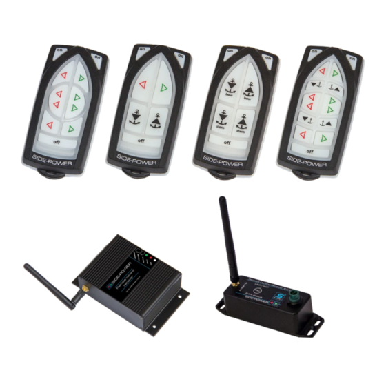
Page 4: Remote Control Kits
Remote Control Kits MC_0228 The transmitters and receivers are sold as individual products and in kits. The content of the different kits is described below. Remote control kit RC-20U/E consists of: Remote control kit RC-21U/E consists of: - Receiver: Part no. RCR-2U/E - Receiver: Part no. -
Page 5: Remote Layout & Functions
Remote Layout & Functions MC_0175 Remote Transmitter RCT-20(U/E) RCT-21(U/E) *U For the USA confi guration *U For the USA confi guration *E For European confi guration *E For European confi guration Turn ‘ON’ the Turn ‘ON’ the remote radio remote radio Bow directional control for Dual Bow and stern Directional control... -
Page 6: User Operation
! Please refer to the graphic for special considerations relating to your model ! The following is an operation guide to ALL Sleipner control products. Ensure to familiarise yourself with the functionality and operation of your specifi c control device. - Page 7 Activating the bow thruster Activating the stern thruster Activating both bow and Activating both bow and stern thruster to push the stern thruster to rotate the boat sideways boat on axis Activating lowers Anchor/ Activating raises Anchor/ Windlass Windlass MG_0190 RCT 20E, 21E, 22E, 23E &...
-
Page 8: Programming Additional Transmitters/ Remote Controls
Programming Additional Transmitters/ Remote Controls MC_0181 ! Please refer to the graphic for special considerations relating to your model ! The original transmitter and receiver have the same factory pre-set code so that no programming is necessary. When additional transmitters remote controls are to be used, the additional transmitters/remote controls have to be paired with the receiver. - Page 9 Programming Additional Transmitters/ Remote Controls MC_0202 ! Please refer to the graphic for special considerations relating to your model ! The original transmitter and receiver have the same factory pre-set code so that no programming is necessary. When additional transmitters remote controls are to be used, the additional transmitters/remote controls have to be paired with the receiver.
-
Page 10: Transmitter Installation And Battery Replacement
Transmitter Installation and Battery Replacement MC_0178 ! Please refer to the graphic for special considerations relating to your model ! Open the transmitter case by removing the 3 torx screws. Remove the battery by inserting a screwdriver or similar between battery and holder at point A and flip the battery out, taking care not to damage the battery grips at point B. -
Page 11: Transmitter Led Operation And Alarm Indication
Transmitter LED Operation and Alarm Indication MC_0182 State LED status Alarm status Transmitter ON The yellow LED’s No sound blink each second Buttons activated The yellow LED’s No sound blink fast Pairing mode All LED’s on No sound Connection lost Red LED is blink- 3 beeps from the ing once each... -
Page 12: Responsibility Of The Installer
Sleipner products. If you are interfacing the S-Link™ bus by agreement with Sleipner through a designated Sleipner supplied interface, you are still required to install at least one original Sleipner control panel to enable efficient troubleshooting if necessary. -
Page 13: S-Link Receiver Installation
S-Link Receiver Installation MC_0183 ! Please refer to the graphic for special considerations relating to your model ! • Install the receiver minimum 1 meter (3ft) from high power cables and data communication cables or other sources of electrical interference, i.e. navigation instruments, radio communication devices, electric motors and generators. -
Page 14: Receiver Installation
Receiver Installation MC_0177 ! Please refer to the graphic for special considerations relating to your model ! • Install the receiver minimum 1 meter (3ft) from high power cables and data communication cables or other sources of electrical interference, i.e. navigation instruments, radio communication devices, electric motors and generators. -
Page 15: Technical Specifications
Transmitter/Receiver - Technical Specifi cations MC_0176 Transmitter Receiver Power feed 1x3V battery (type: CR2032) 12V or 24V power source Frequency (MHz) 868 MHz 868 MHz RF-power <10mW <10mW Operation temp. -10°C / +55°C -10°C / +55°C HxWxD (mm) 107x47x21 83x136x36 Weight (g) Voltage 8-30V... -
Page 16: Technical Wiring Diagram
Technical Wiring Diagram IMPORTANT Cables/wires must be cable tied well. To Thruster To Thruster Control Panel Control Panel RCT-20(U/E) STERN To Bow To Stern Thruster Thruster BLACK FUSE Battery 12/24V IMPORTANT Power cables must be connected to the battery as shown. Remaining wires must be cable tied well. - Page 17 Technical Wiring Diagram IMPORTANT Cables/wires must be cable tied well. To Thruster To Thruster Control Panel Control Panel RCT-21(U/E) STERN To Bow To Stern Thruster Thruster BLACK FUSE Battery 12/24V IMPORTANT Power cables must be connected to the battery as shown. Remaining wires must be cable tied well.
- Page 18 Technical Wiring Diagram IMPORTANT Cables/wires must be cable tied well. To Thruster To Thruster Control Panel Control Panel RCT-22(U/E) STERN To Bow To Stern Thruster Thruster BLACK FUSE Battery 12/24V IMPORTANT Power cables must be connected to the battery as shown. Remaining wires must be cable tied well.
- Page 19 Technical Wiring Diagram IMPORTANT Cables/wires must be cable tied well. To Thruster To Thruster Control Panel Control Panel RCT-23(U/E) STERN To Bow To Stern Thruster Thruster BLACK FUSE Battery 12/24V IMPORTANT Power cables must be connected to the battery as shown. Remaining wires must be cable tied well.
-
Page 20: Output Signals Diagram
Output Signals Diagram RED - Thruster Positive Thruster Bow BLUE - Thruster STBD GREY - Thruster PORT YELLOW - Automatic Main switch Enable RED - Thruster Positive BLUE - Thruster STBD Thruster Stern GREY - Thruster PORT YELLOW - Automatic Main switch Enable RED - Common BLUE - Windlass IN Windlass Bow... -
Page 21: S-Link System Description
MC_0120 S-Link is a CAN-based control system used for communication between Sleipner products installed on a vessel. The system uses BACKBONE Cables as a common power and communication bus with separate SPUR Cables to each connected unit. Units with low power consumption are powered directly from the S-Link bus therefore one power cable must be connected to the BACKBONE Cable through a T-Connector. -
Page 22: Technical Wiring Diagram
Technical Wiring Diagram MG_0195 RCT 20E, 21E, 22E, 23E & REMOTE RECEIVER 2955 2022... -
Page 23: Service And Support
10. This warranty gives you specific legal rights, and you may also have other rights which vary from country to country. Patents MC_0024 At Sleipner we continually reinvest to develop and offer the latest technology in marine advancements. To see the many unique designs we have patented visit our website www.sleipnergroup.com/patents RCT 20E, 21E, 22E, 23E & REMOTE RECEIVER... - Page 24 With ISO 9001 certificate: 1484-2007-AQ-NOR-NA, issued by DNV-GL Declare that the product: Product Description: Remote control kit Model Numbers: RC-20E containing RCT-20E and RCR-2E RC-21E containing RCT-21E and RCR-2E RC-22E containing RCT-22E and RCR-2E RC-23E containing RCT-23E and RCR-2E RCS-20E...
- Page 25 With ISO 9001 certificate: 1484-2007-AQ-NOR-NA, issued by DNV-GL Declare that the product: Product Description: Remote control kit Model Numbers: RC-20E containing RCT-20E and RCR-2E RC-21E containing RCT-21E and RCR-2E RC-22E containing RCT-22E and RCR-2E RC-23E containing RCT-23E and RCR-2E RCS-20E...
- Page 26 © Copyright Sleipner Motor AS, 2021 The information given in the document was correct at the time it was published. However, Sleipner Motor AS can not accept liability for any inaccuracies or omissions it may contain. Continuous product improvement may change the product specifi...
Need help?
Do you have a question about the RCT-20E and is the answer not in the manual?
Questions and answers