
Related Manuals for Actelis Networks ML630R

Summary of Contents for Actelis Networks ML630R
- Page 1 User Manual ML630R G.SHDSL L3 CPE User Manual Release R1.0 Revision No. A05 Document No. 520R69691E...
- Page 2 Actelis Networks be liable for incidental or consequential damages in connection with or arising from the use of the ML630R series, modules, accessories kits, this manual or any related materials. Actelis Networks reserves the right to revise this publication from time to time and to make changes in the content hereof without obligation to notify any person of such revisions or changes.
- Page 3 Actelis Networks World Wide Web site http://www.Actelis.com • Mail to: Actelis Networks customer support Mailto: techsupport@actelis.com for technical support. • Customer support: Contact Actelis Networks Customer Support directly at one of the following • numbers: Belgium: (0) 800 71180 •...
- Page 4 ML630R Certification FCC Class A Compliance ML630R models, which comply with the limits for class A) comply with the limits for a Class A digital device, pursuant to part 15 of the FCC rules. Warning: ML630R models are Class A product. In a domestic environment, this product may cause radio interference, in which case you may be required to take adequate measures.
- Page 5 2A min. and 5A max. A 5A circuit over current protective device can feed two ML630R units in rack mount shelf. 13. The equipment shall be connected to a properly earthed supply system.
- Page 6 ML630R user manual Prevention of Electrostatic Discharge (ESD) Damage 1. When working with electronic components, wear a commonly grounded antistatic wrist strap to discharge the static voltage from your body in accordance with approved standards. 2. Do not use any devices capable of generating or holding a static charge in the work area where you install or remove electronic components.
- Page 7 évaluations. 10. De nombreux câbles de ce produit sont fournis par la société Actelis Networks. Les câbles qui sont fournis par le client doivent adhérer aux normes des autorités d'inspection et relèvent de la responsabilité du client. Pour diminuer le risque d'incendie, assurez vous que les câbles soient sur la liste UL ou certifiés CSA.
- Page 8 ML630R user manual Prévention des décharges électrostatiques (ESD) Dommages Lorsque vous travaillez avec des composants électroniques, portez un bracelet antistatique mis à la terre pour décharger l'électricité statique de votre corps en conformité avec les normes approuvées. Ne pas utiliser d'appareils capables de générer ou maintenir une charge statique dans la zone de travail où vous installez ou supprimez des composants électroniques.
- Page 9 Bevor Sie Anschlüsse an die Switche durchführen, bitte sorgfältig die Hinweise in den Benutzerhandbüchern durchlesen. 10. Viele der an die Switche angeschlossenen Kabel, werden von Actelis Networks geliefert. Kabel welche nicht von Actelis Networks geliefert werden, müßen den sonstigen Sicherheitsvorschriften entsprechen. Um Risiken zu vermeiden, sollten Kabel UL oder CSA zertifiziert sein.
- Page 10 ML630R user manual Transportieren Sie die Geräte nur in passenden antistatischen Verpackungen. Hinweis für Endverbraucher Das gekaufte Actelis Produkt unterliegt der Richtlinie 2002/96 / EG des Europäischen Parlaments und des Rates der Europäischen Union über Elektro- und Elektronik-Altgeräte (WEEE). Es wurde unter Anwendung der Direktive nach dem 13.
- Page 11 ML630R user manual About This Manual This section provides a guide on how to use the manual effectively. The manual contains information needed to install, configure, and operate ML630R Series units. The summary of this manual is as follows: Chapter 1: Overview Describes ML630R Series in several applications.
- Page 12 ML630R user manual Symbols Used in This Manual 3 types of symbols are used throughout this manual. These symbols are used to advise the users when a special condition arises, such as a safety or operational hazard, or to present extra information to the users.
-
Page 13: Table Of Contents
4.1. Ethernet Interface .............................. 28 OAM ................................. 30 Technical Specifications ..........................31 III. INTERFACES ..........................33 Front Panel of ML630R series ........................34 7.1. Status Indicators ..............................34 7.2. The RST Button ..............................35 7.3. The TST Button ..............................35 Rear Panel ................................ - Page 14 ML630R user manual 16.1. Load Local Profile ............................. 50 16.2. Local Setting ..............................50 16.3. User Management .............................. 54 16.4. TACACS+ ................................. 55 16.5. Date & Time (Local/Remote*) .......................... 56 16.6. General Setup (Local/Remote*) ........................57 16.7. DHCP Server ..............................58 16.8.
- Page 15 ML630R user manual Application Examples ............................. 96 22.1. Bridge ATM Application ........................... 96 22.2. VLAN Application ............................99 22.3. Basic Routing ..............................107 22.4. NAT Routing Application ..........................110 22.5. VLAN Multiplexer Application ........................113 CLI OPERATION ......................... 119 Connection via Craft Port ..........................120 Connection via Telnet/SSH Protocol ......................
- Page 16 25.60. “vrrpset” Command ............................154 25.61. “lfpget” Command ............................154 25.62. “lfpset” Command ............................154 PIN ASSIGNMENT ............................I Console Pin Assignment ............................. i MLP RJ-45 Pin Assignment ..........................i ETH RJ-45 Pin Assignment ..........................ii ML630R DIP switches ............................ii - 15 -...
- Page 17 ML630R user manual FIGURES Figure 3-1 Front Panel of ML630R series ..................... 34 Figure 3-2 Rear Panel of ML630R Series (12VDC) ..................36 Figure 4-1 ML630R Series DSL Interface ..................... 42 Figure 4-2 ML630R Series DIP Switch ......................43 Figure 5-1 Login Page ............................46 Figure 5-2 Language selection ..........................
- Page 18 ML630R user manual Figure 5-23 ACL Setting ..........................64 Figure 5-24 Show ACL Table .......................... 64 Figure 5-25 Local/Remote* User Interface ...................... 65 Figure 5-26 Serial port to IP application ..................... 66 Figure 5-27 Convert serial port to IP Network .................... 67 Figure 5-28 QoS Setup .............................
- Page 19 ML630R user manual Figure 5-53 Account Protection........................87 Figure 5-54 Performance History ........................ 88 Figure 5-55 Ethernet Statistics ........................88 Figure 5-56 Software Default ........................89 Figure 5-57 Factory Default ..........................89 Figure 5-58 HTTP File Upload ........................90 Figure 5-59 Local Save ............................ 90 Figure 5-60 HTTP Uploading File ........................
- Page 20 ML630R user manual Figure 5-83 VLAN Test Result – 6 ........................ 106 Figure 5-84 Routing Application ........................107 Figure 5-85 CO-G.SHDSL ..........................107 Figure 5-86 CO-VLAN ..........................108 Figure 5-87 CO-Virtual IP ..........................108 Figure 5-88 CPE-Virtual IP ..........................109 Figure 5-89 NAT Routing Application ......................
- Page 21 ML630R user manual Figure 6-7 “aclset” Command ........................123 Figure 6-8 “aclget” Command ........................124 Figure 6-9 “arp” Command ......................... 124 Figure 6-10 “atmset” Command ........................ 125 Figure 6-11 “atmget” Command ....................... 126 Figure 6-12 “briget” Command ......................... 126 Figure 6-13 “briset”...
- Page 22 ML630R user manual Figure 6-37 “ping” Command ........................138 Figure 6-38 “run” Command ........................139 Figure 6-39 “remote” Command ....................... 139 Figure 6-40 “rmon” Command ........................139 Figure 6-41 “sysset” Command ......................... 140 Figure 6-42 “sysget” Command ........................ 141 Figure 6-43 “show”...
- Page 23 Figure A-4 DIP switches ..........................ii TABLES Table 2-1 Technical Specifications of the ML630R Series ................31 Table 3-1 Indicators on Front Panel of ML630R series ................34 Table 4-1 10/100Base-T Connection ......................41 Table 4-2 Table Craft Port connections in DB9 connector................41 Table 5-1 The Example of EtherType ......................
-
Page 24: Overview
ML630R user manual Overview This chapter begins with a general description of the ML630R Series. The chapter then describes examples of several applications. -
Page 25: Overview
G.SHDSL bit rate can be configured (or rate adapted) to adapt to the line conditions. The ML630R is G.SHDSL.bis transmission equipment that uses EFM/ATM frames to enable Ethernet extension. ML630R provides local loopback functions thereby enabling system configuration, testing, performance and alarm monitoring of the... -
Page 26: Specification
ML630R User Manual II. Specification To provide understanding of the ML630R Series, this chapter starts with its main features. The chapter then continues to present the SHDSL.bis interface, the network side interface, timing and synchronization, OAM (Operation, Administration and Maintenance) and technical specifications. -
Page 27: Main Features
ML630R User Manual 2. Main Features Listed below are the main features of the ML630R Series: ML630R series supports EFM and ATM mode. Point-to-point G.SHDSL.bis/Ethernet copper lines. EFM mode complies with ITU-T G991.2 standard, TC-PAM 4/8/16/32/64/128 line coding and IEEE 802.3ah 2Base-TL bonding. -
Page 28: Shdsl Interface
ML630R User Manual 3. SHDSL Interface Meet ITU-T G.991.2 & ETS TS 101 524. Bonding protocol: IEEE 802.3ah EFM 2Base-TL Support power back off functions. Modulation Method: 4-TCPAM, 8-TCPAM, 16-TCPAM, 32-TCPAM, 64- TCPAM and 128-TCPAM (4/8/16/32/64/128 levels Trellis Coded Pulse Amplitude Modulation). -
Page 29: Network Side Interface
ML630R User Manual 4. Network Side Interface 4.1. Ethernet Interface Provide a 10/100 Base-Tx auto sensing and half/full duplex configurable Ethernet Interface. Physical Connection Type: Standard RJ-45 connector Comply with the IEEE 802.3 / IEEE 802.3u IEEE 802.3x Flow Control pause packet for Full Duplex in case buffer is full ... - Page 30 ML630R User Manual Static Routing protocol and dynamic routing protocol include RIPv1/v2, OSPFv2, BGP-4 and Virtual Router Redundancy Protocol (VRRP) VPN provides PPTP & L2TP protocol Firewall Anti-DDOS attack & ACL security protection IEEE G.8032 Ethernet Ring Protection Switch (ERPS)
-
Page 31: Oam
ML630R User Manual 5. OAM OAM (Operation, Administration and Maintenance) of the ML630R Series is listed below: Configuration via DIP switches, Telnet (SSH), WEB GUI (HTTP/HTTPS) , SNMP v1/v2c/v3 and TR-069 CID Console: DB9 connector for command line interface (CLI) operation ... -
Page 32: Technical Specifications
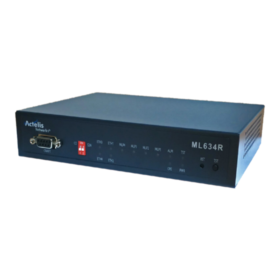
ML630R User Manual 6. Technical Specifications The following table gives the technical specifications of the ML630R Series. Table 2-1 Technical Specifications of the ML630R Series Modulation TC-PAM 4/8/16/32/64/128 Mode Full duplex with echo cancellation Two pairs on ML632R Number of pairs Four pairs on ML634R N*64+8K (N=3~238) up to 15.232Mbps (1 pair), (N=6~576) - Page 33 ML630R User Manual LAN1-4 : Ethernet link indicator : Alarm indicator : Test status indicator 115200bps Craft port 8 bit data length, None parity, 1 stop bit 9-pin/D-sub/female connector, DCE mode 300~115200bps 5~8 bit data length, Even/Odd/None parity, 1 or 2 stop bit...
-
Page 34: Interfaces
ML630R User Manual III. Interfaces In this chapter, the ML630R interfaces will be discussed, and the the front & real panels. EFM/ ATM models Model G.SHDSL LAN G.8032 DIP SW Craft ML632R 2 pairs ● DB-9 ML634R 4 pairs ●... -
Page 35: Front Panel Of Ml630R Series
The front panel of ML630R, as illustrated in Figure 3-1, contains four main sections, management (craft) port, status indicators, DIP switch and buttons. Via the front panel of ML630R Series, users can perform the functions as listed below: • Displaying system status •... -
Page 36: The Rst Button
ML630R User Manual 7.2. The RST Button There is one “RST” Reset button to manually reset the device. Pushing the RST (reset) button for over 5 seconds will manually reset the device back to its factory default setting; including login username, password, IP address and all configuration. -
Page 37: Rear Panel
ML630R User Manual 8. Rear Panel The figure below illustrates the rear panel of the ML630R Series. Users may connect the ML630R Series to other devices or equipment via these interfaces. Figure 3-2 Rear Panel of ML630R Series (12VDC) The following connectors/devices appear on the rear panel of the ML630R Series. -
Page 38: Installation
ML630R User Manual IV. Installation This chapter describes the installation process for the ML630R. It begins with a checklist for unpacking the shipping package. -
Page 39: Unpacking
ML630R User Manual 9. Unpacking ML630R Series shipping package includes the following items: ML630R Series standalone unit AC to DC Power adapter G.SHDSL cable (RJ45-RJ45) Junction Box (from RJ45 to 8 wires) ... -
Page 40: Site Requirements
10.2. AC/DC Electrical Outlet Connection The ML630R Series with 12VDC input should be installed with the provided AC/DC power adapter which has an AC input range of 100 to 240VAC at a frequency of 50Hz to 60Hz. For redundancy, a second AC/DC adapter (not... -
Page 41: Grounding
ML630R User Manual 10.3. Grounding Make sure the electrical power in your building is properly grounded as described in article 250 of the National Electrical Code (NEC) handbook. Verify that a good copper wire of the appropriate gauge, as described in Tables... -
Page 42: Cable Connection
10Base-T or 100Base-T Network. 11.2. Connecting the Terminal The console port connector labeled “CRAFT” on the front panel of ML630R is provided for connection to an external ANSI or VT-100 compatible terminal to perform local configuration of ML630R. -
Page 43: Connecting The Dsl On Devices
ML630R User Manual 11.3. Connecting the DSL on Devices ML630R series provides 1, 2, or 4 pairs connection on the DSL port. Figure 4-1 ML630R Series DSL Interface The DSL interface uses the RJ-45 MLP (Modem Line Port) connector for... -
Page 44: Quick Setup
ML630R User Manual 12. Quick Setup ML630R Series has a “DIP Switch” on the front panel for quick setup. It provides users a quick method to configure the device for CO (Central Office) or CPE (Customer Premises Equipment) operation. Figure 4-2... -
Page 45: Web Interface
ML630R User Manual V. Web Interface In this chapter, the user will be introduced to the web interface of ML630R Series. The chapter starts with an overview of device’s web interface. In additional, each main menu item of the web interface, such as Configuration, Maintenance and Status will be explained thoroughly. -
Page 46: Overview
Users should initially connect to the LAN port, which is the default management port, and enter the IP address as the URL in the Internet browser. The default management IP address is http://192.168.0.1. ML630R supports the following WEB browsers: 1. Microsoft Edge 80+ 2. FireFox 80+ 3. -
Page 47: Login Page
ML630R User Manual 14. Login Page In this page, users need to enter the correct user name & password. There are three default accounts with different privileges. Administrator - username: admin, password: admin Operator (user) - username: user, password: user ... -
Page 48: Status
ML630R User Manual 15. Status The local status can be obtained in this section. 15.1. Local Status For the 4-pairs model (ML634R), there are four loop indexes: MLP1, MLP2, MLP3 and MLP4. Thus, MLP1 and MLP2 are available for the 2-pairs model (ML632R), and MLP1 is only available for the 1-pair model (ML631R). -
Page 49: Figure 5-4 Line Status
ML630R User Manual Figure 5-4 Line Status Note: For the 4-pairs model (ML634R), the total speed is the summary of all the loops’ Line Rate. For instance, if two loops are at speed (199 x 64kbps = 12736kbps), the total speed of DSL trunk is 12736 + 12736 = 25472kbps. -
Page 50: Figure 5-6 Ml630R Current Performance
ML630R User Manual Figure 5-6 ML630R Current Performance... -
Page 51: Configuration
ML630R Series supports Local configuration. 16.1. Load Local Profile There are two default profiles in ML630R for users to select, as shown in the Figure below. The default profile is CPE mode. If a pair of ML630R are connected via DSL in the field, users can select the one profile for CO mode (profile 1) and another one to CPE mode (profile 2) for quick setup. -
Page 52: Figure 5-8 Local/Remote* Setting In Different Mode
Only the ML630R in CO mode can change the setting of “Power Back off”. As soon as it set to “Manual”, then “PBO value” (Power Back off value) can be configured from 0 to 31 dB attenuation. -
Page 53: Figure 5-9 Local/Remote* Setting In G.shdsl
(G.SHDSL.bis - G.991.2 annex F&G) to reach higher data rates. TC-PAM 128 supports up to 238 x 64Kbps = 15Mbps. Miscellaneous: For the ML630R Series, the setting is fixed. CO side is “Internal”, and CPE side is “Recovery from DSL”. -
Page 54: Figure 5-10 Local/Remote* Setting In Ethernet
ML630R User Manual Figure 5-10 Local/Remote* setting in Ethernet Note: Remote setting is only valid when ML630R is deployed as both the CO and CPE 16.2.2. ATM Settings in ATM mode There are two main forms in ATM: General Configure and ATM Parameters. -
Page 55: User Management
ML630R User Manual Figure 5-11 Local/Remote* setting in ATM Note: Remote setting is only valid when ML630R is deployed as both the CO and CPE 16.3. User Management In this page, there are three default privileges for different users’ priorities. To improve security in the ML630R, remember to configure the correct security mechanism when creating new accounts. -
Page 56: Tacacs
ML630R User Manual Figure 5-12 User Management 16.4. TACACS+ TACACS+ (Terminal Access Controller Access-Control System Plus) improves on TACACS functions of Authentication, Authorization and Accounting by encrypting all traffic between the NAS and the daemon. It is flexible allowing for site customization and future development features, and it uses TCP to ensure reliable delivery. -
Page 57: Date & Time (Local/Remote*)
SNTP server for retrieving the time, or to set the time manually. The [Daylight saving time] function moves the clock back by one hour. Figure 5-14 Local/Remote* Date & Time Note: Remote setting is only valid when ML630R is deployed as both the CO and CPE... -
Page 58: General Setup (Local/Remote*)
DSL link to check the security password again. Figure 5-15 Local/Remote* General Setup Note: Remote setting is only valid when ML630R is deployed as both the CO and CPE Note: The IP Address assignment of “System IP” may switch to “Virtual IP”... -
Page 59: Dhcp Server
ML630R User Manual 16.7. DHCP Server Configuration: The default tab is configuration. Users can change the DHCP mode from OFF to DHCP server or DHCP relay (The server & client need to be in the same network). If the operator configures the SHDSL modem as DHCP server, the most important settings are “Start IP”... -
Page 60: Ipv6 (Local/Remote*)
Figure 5-17 Local/Remote* IPv6 Note: Remote setting is only valid when ML630R is deployed as both the CO and CPE 16.9. SNMP & SysLog To set up the destination IP address for sending traps or syslog, users can go to... -
Page 61: Figure 5-18 Snmp Trap Server
[Trap IP] submenu. Input and activate the desired IP address / Domain name. The setting value will activate by pressing the “Apply” button. When the trap or syslog IP is configured, the ML630R alarm information will send to these destination addresses. The trap IP address is usually the address of the SNMP network management system. -
Page 62: Figure 5-20 Snmp V3 Setup
ML630R User Manual Figure 5-20 SNMP v3 Setup Users can change the severity in the trap list. The configurable severity levels are critical, major, minor and warning. Remember to click the “Apply” button after configuring. Figure 5-21 Trap List... -
Page 63: Figure 5-22 The Tr-069 Parameters
16.10. TR-069 The ML630R supports the TR-069 protocol, which acts as an ACS client. All parameters in this form are designed to communicate with ACS server. In order to pass the ACS certification successfully, ensure that all parameters are consistent with each ACS server and client. -
Page 64: Access List
ML630R User Manual 16.11. Access List In order to filter data packets, ML630R needs to set a series of rules for identifying what needs to be filtered. The device supports ACL “White List” mode and “Normal” mode. White List: Any data matching the rules to pass through the devices, otherwise, the ... -
Page 65: Figure 5-23 Acl Setting
ML630R User Manual Figure 5-23 ACL Setting Before clicking “Apply” to set the ACL setting, please make sure that the rules will not cause the WEB management to drop. After clicking the “Apply” button, users can check the rules in “Show ACL Table”. -
Page 66: User Interface
"Limited", only the operators set in the "Management IP/Mask" range have the right to control device. Figure 5-25 Local/Remote* User Interface Note: Remote setting is only valid when ML630R is deployed as both the CO and CPE 16.13. Ser2Net Repackaging RS-232 data as IP packets and then transmitting them through the network is one kind of smart solution for an industrial center. -
Page 67: Figure 5-26 Serial Port To Ip Application
ML630R User Manual Figure 5-26 Serial port to IP application Admin – Turn ON or turn OFF the serial port for IP function. Caution: When the Admin is turned to ON, the Ser2Net function may affect the console functionality. Please remember to use a static IP address for WEB management, in case either Console or Ser2Net is used. -
Page 68: Figure 5-27 Convert Serial Port To Ip Network
ML630R User Manual Figure 5-27 Convert serial port to IP Network... -
Page 69: Bridge / Routing
The ML630R has the ability to provide different priority to different applications, or to guarantee a certain level of performance to a data flow on different ports. -
Page 70: Figure 5-29 Vlan Rule
ML630R User Manual Figure 5-29 VLAN Rule The Ethernet switch can use the VLAN information to select which ports to forward traffic to. Based on IEEE 802.1Q, the VLAN table is used to handle traffic in accordance with user-defined forwarding rules, with up to 4094 VLAN rules. -
Page 71: Figure 5-31 Tag-Based Vlan
ML630R User Manual Tag-based VLAN is based on IEEE 802.1Q. This mode is used to handle traffic in accordance with user-defined forwarding rules that are based on the IEEE 802.1Q tags of the frames. For the external LAN ports, users are able to select whether to discard untagged frames or process them. -
Page 72: Virtual Ip
ML630R User Manual Figure 5-32 Q-in-Q CVID: Customer VIDs, used for INNER Tag. SVID: Service VIDs, used for OUTER Tag. TVID: Target VIDs, used for a Translated Tag. Core: Working mode as Core (Trunk) port or Edge (Tributary) port. -
Page 73: Figure 5-33 Virtual Ip
ML630R User Manual Figure 5-33 Virtual IP Add: The first parameter is “VLAN”. Define VLANs which are configured in the VLAN table for acting new interface. Operators are able to configure various Modes (Static IP / DHCP client / PPPOE/ PPTP/ L2TP), IP network, default Gateway, secondary IP and so on, based on different application. -
Page 74: Routing
ML630R User Manual 17.4. Routing There are three main tables in this menu, “Routing Table”, “Static Route” and “Dynamic Route”. Users have to enable “Tag-based” or “Q-in-Q” in VLAN rule to activate the routing mode. Routing Table: The default tab is “Routing Table”, to check routing rules ... -
Page 75: Figure 5-36 Static Route
ML630R User Manual Figure 5-36 Static Route Dynamic Route: ML630R supports RIPv1(Classful Routing Protocol), RIPv2(Classless Routing Protocol), OSPFv2 and BGP4 routing protocols. All network units with RIPv1/v2 in the same network will keep checking each routing rules, but only RIPv2 supports trigger update. While running dynamic route function, remember that only RIPv2 has VLSM (Variable Length Subnet Masking). -
Page 76: Vrrp
ML630R User Manual 17.5. VRRP VRRP (Virtual Router Redundancy Protocol) specifies an election protocol that dynamically assigns responsibility for a virtual router to one of the VRRP routers on a LAN. The VRRP router controlling the IP address(es) associated with a virtual router is called the Master, and forwards packets sent to these IP addresses. -
Page 77: Nat
ML630R User Manual Figure 5-39 Setup VRRP Table Admin: To turn the virtual router interface ON or OFF. Router ID: Two physical DSL Routers should apply the same router ID to act as one virtual router. Router Priority: Two physical DSL Routers apply this priority to switch between ... -
Page 78: Figure 5-40 Nat Table
ML630R User Manual Figure 5-40 NAT Table 17.6.1. NAT Table There are three options in the NAT table, “Add”, “Update” and “Delete”. If users would like to add a NAT rule, they can click the “Add” button, or update and delete any rules. -
Page 79: Figure 5-42 Nat Configuration
ML630R User Manual Start Port & End Port: Used for a series of TCP and UDP port numbers. It can only be configured if the protocol is not “ALL”. Destination IP: A specified IP or a range of destination IPs. -
Page 80: Dns
17.7. DNS DNS is the name service of Internet addresses that translates friendly domain names to numeric IP addresses. ML630R supports DNS Server & DNS cache. Firstly, users have to enable “Tag-based” in VLAN rule to activate the DNS function. If the modem acts as a DNS Server, enable the “Authoritative Server Mode”. -
Page 81: Figure 5-44 Dns Server/Cache
Figure 5-44 DNS Server/Cache 17.8. G.8032 ML630R provides ERPS (Ethernet Ring Protection Switch) according to ITU-T G.8032 standard. With this feature, not only a serial linear network can be supported but also ring topology. The downside of a serial linear network is any failure of any nodes or ports would affect traffic for the whole network. -
Page 82: Figure 5-46 Owner And Member For Ring Topology
ML630R User Manual Current Alarm When current Ethernet packets loop alarms occurred, logs will be displayed and updated immediately in this form. “Normal” means the ring topology has been completed with no errors. General Setup Admin: Select “Enable” to run G.8032. -
Page 83: Figure 5-47 General Setup
ML630R User Manual Figure 5-47 General Setup Group Member When the device is “Owner”, users are able to check all online “Members” in this form. Click “Add all candidate” to add members to G.8032 Group Member. Figure 5-48 Group Member... -
Page 84: Rstp
ML630R User Manual 17.9. RSTP ML630R provides RSTP (Rapid Spanning Ring Protection) according to the IEEE 802.1w standard. With this feature, each device can be connected in a linear, ring or mesh topology and prevent traffic broadcast storms (Ethernet loops) in the network. -
Page 85: Figure 5-50 Rstp Status And Port Status
ML630R User Manual hello BPDUs. If the maximum message age timer expires, the bridge detects that the link to the root bridge has failed and initiates a topology re-convergence. The maximum message age timer should be longer than the configured hello timer. - Page 86 ML630R User Manual Forwarding: The MAC address is learning and forwarding. Learning: The Learning state appears for a short period of time while the Alternate Port and Backup Port replaces the Root port. Discarding: Disable, Blocking and Listening port state in STP is the same as the Discarding port state in RSTP.
-
Page 87: Maintenance
ML630R User Manual 18. Maintenance 18.1. Alarm Log The alarm history is displayed in this section. The network manager can check different the severity levels of logs according to the system time. Figure 5-51 Alarm Log... -
Page 88: Local Access Log
5 minutes after 3 incorrect password attempts. The system displays any unauthorized IPs. When incorrect login authentication is entered more than five times, the ML630R will refuse the IP address. Manually clearing the table records will recover the blocked IPs. -
Page 89: Performance History
ML630R User Manual 18.4. Performance History The performance history shows the errors occurring on each loop by 15 minutes or 1 day duration. The system supports Local/Remote* G.SHDSL performance history. Users can manually update all records. Figure 5-54 Performance History 18.5. -
Page 90: Software Default
ML630R User Manual 18.6. Software Default This function is used to restore all settings to factory defaults except the device IP and management authority. After clicking the “Apply” button, the pop-up window will show a confirmation message. Figure 5-56 Software Default 18.7. -
Page 91: Software Upgrade
ML630R User Manual 18.8. Software Upgrade The local device can be upgraded by HTTP, and users can select the correct firmware file for uploading. Step 1: Click “Choose File” to open the folder and enter the software version file. Figure 5-58 HTTP File Upload Step 2: Select “OK”... -
Page 92: Ssl Setting
ML630R User Manual Step 5: During upgrade procedure, all LEDs on the ML630R’s front panel will blink at the same time. Do not turn off the power during this process. The total procedure takes about 3 minutes to return to standby mode. -
Page 93: Ping
ML630R User Manual 18.10. Ping This feature is used to verify whether the packet transmission path is reachable or is alive. Users may select “Interface” for path and input an IP address in “Ping IP” to test. Figure 5-64 Ping... -
Page 94: Save
ML630R User Manual 19. Save 19.1. Local Save Save all Local configurations as a user profile. This will allow the ML630R to save the current configuration and restore it at the next power on. Figure 5-65 Local Save... -
Page 95: About
ML630R User Manual 20. About 20.1. Software Version The system will show the correct model type and software version of ML630R series on local and remote modems. Figure 5-66 Local / Remote Software Version... -
Page 96: Action
ML630R User Manual 21. Action Figure 5-67 Action Logout: Return to the login page Local System Reboot: Restart the local modem. Summary: The operator can upload a summary file including all the configuration, modem status, alarm log, and Ethernet statistics to local storage. It can be analyzed... -
Page 97: Application Examples
ML630R User Manual 22. Application Examples 22.1. Bridge ATM Application Figure 5-68 Bridge ATM Application < CO configuration > 1. Configuration > Local Setting > G.SHDSL Mode= ATM / Side Mode= CO / Wire Mode= 8w Figure 5-69 CO-G.SHDSL... -
Page 98: Figure 5-70 Co-Atm
ML630R User Manual 2. Configuration > Local Setting > ATM Index 2: VID=10 / VPI=7 / VCI=2000 Figure 5-70 CO-ATM 3. Bridge / Routing > VLAN Figure 5-71 CO-VLAN... -
Page 99: Figure 5-72 Cpe-Vlan
ML630R User Manual < CPE configuration > 1. Configuration > Local Setting > G.SHDSL Mode= ATM / Side Mode= CPE / Wire Mode= 8w Figure 5-72 CPE-VLAN 2. Configuration > Local Setting > ATM All settings are same as “CO”. -
Page 100: Vlan Application
ML630R User Manual 4. Bridge / Routing > VLAN All settings are same as CO. VLAN Rule= Tag-based / DSL, CVID=10 Tag a VLAN 1 on DSL Tag a VLAN 10 on LAN-2 & DSL Note: After the modems are connected, it will take about 10 ~ 30 seconds for the high-speed link to synchronize and for data to pass through the DSL. -
Page 101: Figure 5-75 Co-G.shdsl
ML630R User Manual Configuration > Local Setting > G.SHDSL Switch the dip switch on or change the device mode to “CO”. Figure 5-75 CO-G.SHDSL < CPE configuration > 1. Configuration > Local Setting > G.SHDSL The default master-slave relationship of ML634R is “CPE”. -
Page 102: Figure 5-77 Cpe-Vlan
ML630R User Manual Figure 5-77 CPE-VLAN ** Note: Remember to save after configuring. Test Result: Figure 5-78 VLAN Test Result - 1 Table 5-3 VLAN Test Result – 1 Data Direction: Port 1 --> Port 2 Port 1 Port 2... -
Page 103: Figure 5-79 Vlan Test Result - 2
ML630R User Manual Figure 5-79 VLAN Test Result – 2 Data Direction: Port 2 --> Port 1 Port 2 Port 1 Untagged Untagged Tagged 50 (81000032) Untagged Tagged 100 (81000064) Table 5-4 VLAN Test Result – 2... -
Page 104: Figure 5-80 Vlan Test Result - 3
ML630R User Manual Figure 5-80 VLAN Test Result – 3 Data Direction: Port 1 --> Port 2 Port 2 Port 1 Untagged 81000014 Tagged 20 (81000014) 81000014 Tagged 100 (81000064) Table 5-5 VLAN Test Result - 3... -
Page 105: Figure 5-81 Vlan Test Result - 4
ML630R User Manual Figure 5-81 VLAN Test Result – 4 Data Direction: Port 2 --> Port 1 Port 2 Port 1 Untagged 81000032 Tagged 50 (81000032) 81000032 Tagged 100 (81000064) Table 5-6 VLAN Test Result - 4... -
Page 106: Figure 5-82 Vlan Test Result - 5
ML630R User Manual Figure 5-82 VLAN Test Result – 5 Data Direction: Port 1 --> Port 2 Port 1 Port 2 Untagged Untagged Tagged 20 (81000014) Untagged Tagged 100 (81000064) Table 5-7 VLAN Test Result - 5... -
Page 107: Figure 5-83 Vlan Test Result - 6
ML630R User Manual Figure 5-83 VLAN Test Result – 6 Data Direction: Port 2 --> Port 1 Port 2 Port 1 Untagged 81000032 Tagged 50 (81000032) 81000032 Tagged 100 (81000064) Table 5-8 VLAN Test Result - 6... -
Page 108: Basic Routing
ML630R User Manual 22.3. Basic Routing Routing Application: Figure 5-84 Routing Application < CO configuration > 1. Configuration > Local Setting > G.SHDSL Switch the dip switch on or change the device mode to “CO”. Figure 5-85 CO-G.SHDSL... -
Page 109: Figure 5-86 Co-Vlan
ML630R User Manual 2. Bridge / Routing > VLAN Ex. VLAN Rule= Tag-based / DSL, CVID= 2 All ports with VLAN 2 are untagged for the WAN port. Figure 5-86 CO-VLAN 3. Bridge / Routing > Virtual IP Add & Update all Virtual IPs, eth0.1 acts as LAN and eth0.2 acts as WAN. -
Page 110: Figure 5-88 Cpe-Virtual Ip
ML630R User Manual ** Note: Remember to save after configuring. < CPE configuration > 1. Configuration > Local Setting > G.SHDSL The default master-slave relationship of ML634R is “CPE”. 2. Bridge / Routing > VLAN All settings are same as “CO”. -
Page 111: Nat Routing Application
ML630R User Manual 22.4. NAT Routing Application Figure 5-89 NAT Routing Application < CO configuration > 1. Configuration > Local Setting > G.SHDSL Switch the dip switch on or change the device mode to “CO”. Figure 5-90 CO-G.SHDSL 2. Configuration > General Setup > Local... -
Page 112: Figure 5-91 Co-General Setup
ML630R User Manual Figure 5-91 CO-General Setup Note: Remember to save after configuring. < CPE configuration > 1. Configuration > Local Setting > G.SHDSL The default master-slave relationship of ML634R is “CPE”. 2. Bridge / Routing > VLAN Ex. VLAN Rule= Tag-based / DSL, CVID= 2 All ports with VLAN 1 are untagged. -
Page 113: Figure 5-93 Cpe-Virtual Ip
ML630R User Manual Add & Update all Virtual IPs, eth0.1 acts as LAN and eth0.2 acts as WAN. • Figure 5-93 CPE-Virtual IP 4. Bridge / Routing > NAT table Remap the source IP(192.168.0.10) into another IP(172.16.4.10) while packets are •... -
Page 114: Vlan Multiplexer Application
LAN port connections. Each LAN port has its own traffic which is isolated from other LAN ports. Configuration: Control/ Management PC IP address: 192.168.0.170 ML630R at CO IP address: 192.168.0.108 ML630R at CPE IP address: 192.168.0.109 Default Login User Name:... -
Page 115: Figure 5-96 Restore To Software Default
ML630R User Manual 1. To simplify the configuration, all configuration starts by loading the factory default: [Maintenance][Software Default][Apply] Figure 5-96 Restore to software default 2. On CPE site, [Configuration][Load Local Profile]1.CPE [Apply] 3. On CO site, [Configuration][Load Local Profile]2.CO [Apply]... -
Page 116: Figure 5-98 Change Ip Address Of Co Device
ML630R User Manual 4. On the CO site, change the IP address to 192.168.0.108 [Configuration][General Setup]Local [System IP] [IP address] 192.168.0.108 Figure 5-98 Change IP address of CO device 5. On the CPE site, change the IP address to 192.168.0.109 [Configuration][General Setup]Local [System IP] [IP address]... -
Page 117: Figure 5-100 Apply Tag-Based Vlan Rule
ML630R User Manual Change the VLAN Rule to [Tag-based] in Bridge/ Routing group [Bridge/ Routing] [VLAN] [VLAN Rule] Tag-based [Apply] Figure 5-100 Apply Tag-based VLAN rule 7. Edit the VLAN table; the VLAN table will be displayed after Tag-based rule has been selected [Bridge/ Routing] ... -
Page 118: Figure 5-102 Setup Vlan Rule Of Vid 1 And 20
ML630R User Manual Figure 5-102 Setup VLAN rule of VID 1 and 20 [Bridge/ Routing] [VLAN] [VLAN Table] [Add]20 Figure 5-103 Setup VLAN rule of VID 30 and 40 [Bridge/ Routing] [VLAN] [VLAN Table] [Add]30 [Bridge/ Routing] [VLAN] [VLAN Table] [Add]40... -
Page 119: Figure 5-105 Setup The Core Port Vid
ML630R User Manual [Bridge/Routing] [VLAN] Port Configuration [CVID] 1, 1, 20, 30, 40, 1 [Apply] Figure 5-105 Setup the Core port VID 9. [Save][Local Save]SHDSL[OK] Figure 5-106 Save the working configuration to profile 10. Perform the same procedure from steps 6 to 9 on the CPE to complete the whole configuration. -
Page 120: Cli Operation
ML630R User Manual VI. CLI Operation This Chapter describes the ML630R Command Line Interface. There are two methods to access the Command Line Interface: the Craft port and Telnet, both of which provide the same command format. The Craft port is used primarily when the device is installed for the first time and the IP configuration is not yet provisioned. -
Page 121: Connection Via Craft Port
23. Connection via Craft Port By using a VT-100/ANSI compatible terminal emulation software, such as Microsoft HyperTerminal or Tera Term, users can configure the ML630R via the Craft port with a console cable. Select the COM port used and setup the following settings: Speed: 115200 bps (bit per second) ... -
Page 122: Connection Via Telnet/Ssh Protocol
ML630R User Manual 24. Connection via Telnet/SSH Protocol The ML630R default IP address is shown below. Users can update the IP address to access the device by Telnet and SSH protocol. Default IP address: 192.168.0.1 Default gateway: 192.168.0.254 Default netmask: 255.255.255.0... -
Page 123: The Command Line Interface
ML630R User Manual 25. The Command Line Interface After connecting to the ML630R, the terminal UI will display the Root Menu as shown below. The user has to input the correct user name and password for the login process. The default highest authority is admin/admin. -
Page 124: Aclset" Command
ML630R User Manual 25.1. “aclset” Command This command is used to set ACL. ML630R supports two methods, “normal” and “white list” with different match conditions to filter specified data packets. Figure 6-7 “aclset” Command... -
Page 125: Aclget" Command
ML630R User Manual 25.2. “aclget” Command Input this command to get ACL rules. Figure 6-8 “aclget” Command 25.3. “arp” Command Input this command to get the ARP table with options to filter entries matching IP and VLAN. Figure 6-9 “arp” Command 25.4. -
Page 126: Figure 6-10 "Atmset" Command
ML630R User Manual Figure 6-10 “atmset” Command... -
Page 127: Atmget" Command
ML630R User Manual 25.5. “atmget” Command This command is used to check ATM functions, such as CPCS Protocol, VID, VPI and VCI. Figure 6-11 “atmget” Command 25.6. “briget” Command This command is one of the most important commands for routing applications. -
Page 128: Briset" Command
ML630R User Manual 25.7. “briset” Command This command is used to set VLAN parameters. There are three main VLAN rules, such as tag based, port based and Q-in-Q. Tag based Routing mode Port based Bridge mode ... -
Page 129: Communityset" Command
ML630R User Manual 25.8. “communityset” Command This command is used to set SNMPv2 parameters, such as security passwords of Agent Public Community, Agent Private Community and Trap Community. Figure 6-14 “communityset” Command 25.9. “communityget” Command This command is used to get SNMPv2 information, only admin privilege can get SNMP Community information. -
Page 130: Dhset" Command
ML630R User Manual 25.11. “dhset” Command This command is used to set the DHCP parameters, such as server mode, Start IP, End IP, NTP server, DNS server and so on. Also, users are able to add, delete or update specified IP to specified MAC address via “Static Lease”. -
Page 131: Dnsset" Command
ML630R User Manual 25.13. “dnsset” Command This command is used to set the DNS configuration. Figure 6-19 “dnsset” Command 25.14. “exit” Command Input “exit” to log out the system. Figure 6-20 “exit” Command... -
Page 132: Fmget" Command
ML630R User Manual 25.15. “fmget” Command This command is used to display and clear the current alarm logs. Figure 6-21 “fmget” Command 25.16. “gset” Command This command is used to set G.SHDSL parameters, such as CO/CPE mode, line rate, wire mode, line probe, EFM/ ATM mode and so on. -
Page 133: Get" Command
ML630R User Manual 25.17. “get” Command This command is used to check all G.SHDSL parameters. Figure 6-23 “get” Command 25.18. “rpget” Command This command is used to check G.8032 parameters. Network managers can observe all online members in point to multi-point mode. -
Page 134: Rpset" Command
ML630R User Manual 25.19. “rpset” Command This command is used to set G.8032 function. The “-a” parameter can initially be used to see all the information. Depending on whether the topology is a DSL/ Ethernet ring topology or a DSL serial linear network, some parameters may, or may not, be relevant. -
Page 135: Ipv6Get" Command
ML630R User Manual 25.21. “ipv6get” Command This command is used to check the device IPv6. Figure 6-27 “ipv6get” Command 25.22. “ipv6set” Command This command is used to manually configure the IPv6 parameters, including IP, prefix and default gateway. Figure 6-28 “ipv6set”... -
Page 136: Langet" Command
ML630R User Manual 25.24. “langet” Command This command is used to check all LAN parameters. Figure 6-30 “langet” Command... -
Page 137: Load" Command
ML630R User Manual 25.25. “load” Command This command is used to load the factory or default file, allowing users a more convenient way to establish the DSL connection. Figure 6-31 “load” Command 25.26. “maclg” Command This command is used to display the MAC learning table for all ports. -
Page 138: Natget" Command
ML630R User Manual 25.27. “natget” Command This command is used to check NAT rules and each configuration. Figure 6-33 “natget” Command 25.28. “natset” Command This command is used to set the NAT function. There are three main NAT items, “SNAT”, “MASQURADE” and “DNAT”. Different NAT definitions have different rules which need to be configured. -
Page 139: Pmset" Command
ML630R User Manual 25.29. “pmset” Command This command is used to clear all G.SHDSL performance records. Figure 6-35 “pmset” Command 25.30. “pmget” Command This command is used to check all G.SHDSL performance records. Figure 6-36 “pmget” Command 25.31. “ping” Command This command is used to verify the packet transmission path between the modem and other networks. -
Page 140: Run" Command
This command is used to run all settings immediately. Figure 6-38 “run” Command 25.33. “remote” Command If 2 ML630R are connected as local and remote modems, “remote” will access the remote modem via EOC management, or “local” will revert to the local configuration. Figure 6-39 “remote” Command 25.34. -
Page 141: Sysset" Command
ML630R User Manual 25.35. “sysset” Command This command is used to set the system information, such as the system time, link security, system name, description, contact and location. Invoking the “sysset –r” command may reset the device and reload the saved profile. -
Page 142: Sysget" Command
ML630R User Manual 25.36. “sysget” Command This command is used to verify the system information. In general, users can check the IP network parameters within Bridge mode, the MAC address and other system parameters. Figure 6-42 “sysget” Command... -
Page 143: Show" Command
ML630R User Manual 25.37. “show” Command This command is used to show profile, startup or running configuration. Figure 6-43 “show” Command... -
Page 144: Status" Command
ML630R User Manual 25.38. “status” Command This command is used to check the G.SHDSL status. Typically network managers can use this command to check the DSL connection and current line rate. Figure 6-44 “status” Command 25.39. “snmpv3get” Command This command is used to check the SNMPv3 parameters, such as user name, rights and security protocol. -
Page 145: Snmpv3Set" Command
ML630R User Manual 25.40. “snmpv3set” Command This command is used to set SNMPv3 parameters including different security levels, passwords and algorithms which need to be configured Figure 6-46 “snmpv3set” Command 25.41. “save” Command This command is used to save all settings after a change in configuration. -
Page 146: Tacset" Command
ML630R User Manual 25.43. “tacset” Command This command is used to set TACACS+ parameters. Figure 6-49 “tacset” Command 25.44. “rstpg” Command This command is used to get RSTP Parameters and Status. -
Page 147: Rstps" Command
TFTP server. Users have to first prepare a workable TFTP server and place the firmware or configuration profile in the download path. One the file is available, it can be accessed by the ML630R by entering the correct IP, file path and file name. -
Page 148: Tr069S" Command
ML630R User Manual Figure 6-52 “tftp” Command 25.47. “tr069s” Command This command is used to set TR-069 parameters. Modems act as TR-069 clients. In the protocol, clients have their own authentication, and need to match the server’s configuration. Remember to check both sides use the same parameters. -
Page 149: Trapset" Command
ML630R User Manual Figure 6-54 “tr069g” Command 25.49. “trapset” Command This command is used to set the SNMP trap or Syslog IP, trap status, duplication and repeat interval. Figure 6-55 “trapset” Command... -
Page 150: Trapget" Command
Figure 6-56 “trapget” Command 25.51. “userset” Command ML630R supports three levels of security authority: “Administrator”, “Operator” and “Monitor”. Administrators are able to manage all functions, such as add, delete or modify. Password rules can also be configured. Figure 6-57 “userset” Command... -
Page 151: Userget" Command
ML630R User Manual 25.52. “userget” Command This command is used to check all users’ accounts and rights except passwords which are hidden. Figure 6-58 “userget” Command 25.53. “uiget” Command This command is used to check all user interfaces. Figure 6-59 “uiget”... -
Page 152: Vipget" Command
ML630R User Manual Figure 6-60 “uiset” Command 25.55. “vipget” Command This command is used to check “Virtual IP” in routing mode. Figure 6-61 “vipget” Command... -
Page 153: Vipset" Command
ML630R User Manual 25.56. “vipset” Command This command is used to set “Virtual IP” in routing mode. Users have to follow the rules to create, delete or update Virtual IPs. Figure 6-62 “vipset” Command 25.57. “vrget” Command This command is used to check routing rules in the routing table. Routing rules include “Full Routing Table”, “Dynamic Routing Settings”, “Static Routing... -
Page 154: Vrset" Command
ML630R User Manual 25.58. “vrset” Command This command is used to set routing rules. One of the main functions is named “Static Route”, and rules can be manually added or deleted. RIPv1 & RIPv2 are also configurable. Figure 6-64 “vrset” Command 25.59. -
Page 155: Vrrpset" Command
ML630R User Manual 25.60. “vrrpset” Command This command is used to set VRRP parameters, such as Interface VLAN, Priority, and VRRP IP. Figure 6-66 “vrrpset” Command 25.61. “lfpget” Command This command is used to Link Fault Pass through Information. Figure 6-67 “lfpget” Command 25.62. -
Page 156: Figure 6-68 "Lfpset" Command
ML630R User Manual Figure 6-68 “lfpset” Command... -
Page 157: Pin Assignment
Appendix A. User Manual Pin Assignment A.1 Console Pin Assignment DB-9 Pin Description TxD (Out) RxD (In) Figure A-1 DB-9 Interface The Console DB-9 pin assignment is as follows: Table A-1 DB-9 pin assignment A.2 MLP RJ-45 Pin Assignment Tip(2) Ring(2) Tip(4) Tip(2) -
Page 158: Eth Rj-45 Pin Assignment
User Profile / CPE Mode Reserved When both of DIP switches are set to “OFF” and then the ML630R is powered up, the ML630R will load the user’s latest profile which has previously been saved in the system. By default, the ML630R acts in CPE mode with IP address 192.168.0.1.
Need help?
Do you have a question about the ML630R and is the answer not in the manual?
Questions and answers