Table of Contents
Advertisement
Advertisement
Table of Contents

Related Manuals for MULTISOFT VGR-1000


Summary of Contents for MULTISOFT VGR-1000
- Page 1 VIDEO GRABBER VGR-1000 User Manual v. 1.19 (FW 1.29)
-
Page 2: Table Of Contents
Table of contents General description...................... 4 Device overview ......................5 2.1. Front panel ........................5 2.2. Back panel ........................5 2.3. OLED screen ......................... 6 Device installation ......................7 3.1. Introduction ......................... 7 3.2. Connecting video signal cables ..................8 3.3. - Page 3 5.5.5. confLan (subsection 5) ................... 57 5.5.6. confNfs (subsection 6) .................... 59 5.5.7. confSmb (subsection 7) ..................60 5.5.8. confNtp (subsection 8) ................... 61 5.5.9. confEdid (subsection 9) ..................62 5.5.10. confAnalogVideo (subsection 10) ................62 5.5.11. confUpdate (subsection 11) ................... 63 Firmware upgrade ......................
-
Page 4: General Description
To ensure 1:1 capture of the video input lossless encoding should be used. To ensure proper time stamping of the captured data Multisoft Video Grabber supports NTP protocol. Not all formats are available for all protocols. For detailed information see 4.2.1.1 Output protocol, p. 20... -
Page 5: Device Overview
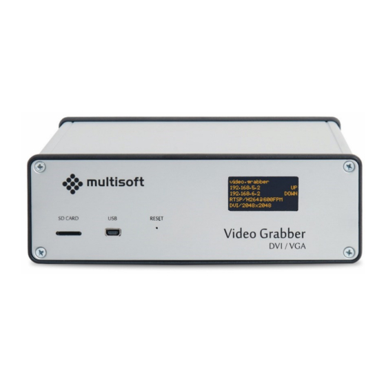
2. Device overview 2.1. Front panel Figure 1: Front panel of the Video Grabber No. Name Description SD Card Used for firmware update and factory reset Used for firmware update and diagnostics Reset Used for resetting the device OLED screen Displays Video Grabber’s runtime information 2.2. -
Page 6: Oled Screen
2.3. OLED screen By default OLED screen displays basic status information of the device. User can configure it to also show a view with NTP status. In such case both ‘views’ are shown at intervals (See 4.2.3 on p. 36 for details on OLED configuration and 4.1.3 on p. -
Page 7: Device Installation
3. Device installation 3.1. Introduction Video Grabber captures the video data that is sent by the computer to the display. To achieve that task it has to be connected between those two devices (see figure below). It is advised to turn off all equipment involved in cable connections (display, recorded computer and Video Grabber) for the time of the installation. -
Page 8: Connecting Video Signal Cables
3.2. Connecting video signal cables Video Grabber has two DVI-I DL (Dual Link) connectors, one for input and one for output of the video signal. Connect source signal (e.g. computer) to Video Input, and display (e.g. monitor) to Video Output. It is advised to use the same types of cables for input and output It is strongly recommended to use single-link DVI cables when resolutions 1920x1200 and below are recorded as some graphic cards generate noise on the unused link which in turn can affect the... - Page 9 Analogue Resolution (width x height) Signal refresh rate Cables 640 x 480 (VGA) 75Hz DVI-I (Dual Link) DVI-I (Single Link) 720 x 400 70Hz DVI-A 800 x 600 (SVGA) 75Hz D-SUB 832 x 624 75Hz 1024 x 768 (XGA) 75Hz 1152 x 870 75Hz 1280 x 720 (HD 720)
-
Page 10: Network Connection
3.3. Network connection Video Grabber has two RJ45 ports, named LAN 1 and LAN 2. When both interfaces are configured and active (connected) then the same data is sent through both of them. This way two independent systems can receive the same data from the Video Grabber using two physically separate connections thus achieving redundancy. -
Page 11: Video Grabber Web Interface
4. Video Grabber Web Interface In order to access Video Grabber Configuration, one can use a web browser . In the address field please type http://video.grabber.ip.address where video.grabber.ip.address - is an IP Address which is displayed on the screen in front of the device. Figure 8: Connecting to Video Grabber's web interface using its default IP address Mozilla Firefox is recommended. -
Page 12: Status Page
4.1. Status page Status page is a default page of the Video Grabber’s web interface. It provides information current operational parameters of the Video Grabber device. This page can be divided into 4 main sections: 1. Device information 2. Device status 3. -
Page 13: Device Information
4.1.1. Device information Figure 10: Device information section of the status page In the first section of the Video Grabber’s status page one can find general information on the device: 1. Date and time – currently set date and time on the Video Grabber. 2. -
Page 14: Device Status
4.1.2. Device status Figure 11: Device status section on the status page In the second section of the Video Grabber’s status page one can find general status information: 1. Free Memory – the amount of free RAM on the device in kilobytes. 2. - Page 15 9. FS1 – status of the second remote file system (NFS2 / SMB2) Shown only in case NFS or SMB protocol is used a. Mounted – remote file system is mounted b. Not accessible – remote file system is not mounted 10.
-
Page 16: Ntp Status
4.1.3. NTP status Video Grabber is synchronizing its internal clock using NTP protocol by connecting to NTP peers. The choice between configured peers is done based on their time source quality . Once configured the synchronization “just works”. However for the rare cases when deep analysis of the NTP synchronization process is required the Status page provides detailed information on the current NTP operational parameters. - Page 17 Figure 13: Detailed information on currently chosen peer 1. system peer – the peer that has been chosen and is used as a clock reference (marked with * in the table above). 2. system peer mode – Video Grabber’s mode of ntp operation. 3.
-
Page 18: Analog Resolution Table
13. broadcastdelay – broadcast delay, set to compensate the network delays when set as broadcast client. By default it is not used by Video Grabber. 14. authdelay – since authentication involves extra computing, authentication delay setting is used to compensate it. Currently calculated automatically (if needed). 4.1.4. -
Page 19: Configuration Page
4.2. Configuration page Access to the Configuration page is password-protected. The login details are as follows: Username: grabber Password: vgbr2014 The Configuration page can be divided into four main sections: 1. Output – settings related to the output format of the captured video signal 2. -
Page 20: Output
4.2.1. Output In the Output section of the Configuration page user can define the format and protocol which will be used by Video Grabber to output captured video signal. Figure 15: Output section on the Configuration page. 1. Output – protocol to be used for output of the video signal data. 2. - Page 21 4. JPEG2000 – newer version of the JPEG format. 5. H.264 – lossy video compression format. 6. LOSSLESS – Multisoft’s proprietary lossless video compression format. When user chooses the RTSP protocol then the format is automatically selected depending on the RTSP connection stream chosen by the user.
- Page 22 4.2.1.4. Video parameters Figure 17: Video parameters settings on the Configuration page If user decides to use either H.264 or LOSSLESS formats then there are few additional parameters that allow further adjustments. One setting – IDR period – is common for both formats. Common for H.264 and LOSSLESS Parameter Description...
- Page 23 H.264 No. Parameter Description Allowed values Enable CBR mode When selected H.264 codec works in CBR mode, Selected when not selected then the H.264 codec works in Not selected VBR mode. CBR – Constant Bit Rate – amount of data sent will be constant.
- Page 24 LOSSLESS No. Parameter Description Allowed values Pixel tolerance Determines the allowed difference between 0 – 31 corresponding R, G, B (Red, Green, Blue) components of pixels. If the difference is not bigger than set value then such pixels are considered identical.
- Page 25 Example: Setting up Video Grabber to emulate a specific monitor. 1. Connect the Video Grabber between the computer and the monitor that is to be emulated See 3.1 (page 7). 2. Open Video Grabber’s web interface. See 4 (page 11). 3.
- Page 26 4.2.1.7. Examples There are plenty of possible Output configuration sets. See sample setups below: Example 1 Video Grabber captures the video signal at a rate of 60 frames per minute (1FPS) and then broadcasts captured data. Figure 19: Sample configuration of Video Grabber broadcasting BMP files Example 2 Video Grabber captures the video signal at a rate of 120 frames per minute (2FPS) and then saves those frames as PNG images on an NFS share.
- Page 27 Example 4 Video Grabber captures the video signal at a rate of 900 frames per minute (15FPS) and then provides a H.264 VBR stream with Quantization Parameter set to 26 and IDR period set to 450. Figure 22: Sample configuration of Video Grabber set to stream captured video signal (H.264 VBR) To connect to the configured H.264 stream user would have to use one of the RTSP connection strings.
- Page 28 Example 6 Video Grabber captures the video signal at a rate of 600 frames per minute (10FPS) and then provides a LOSSLESS stream with bandwidth limit and output limit of 1000kbps. Figure 24: Sample configuration of Video Grabber set to stream captured video signal (LOSSLESS) To connect to the configured LOSSLESS stream user would have to use one of the RTSP connection strings.
-
Page 29: Network
4.2.2. Network In the Network section of the Configuration page user can configure settings related to Video Grabber’s network interfaces (LAN1 and LAN2) along with access details to NFS and SMB shares should they be used. Figure 25: Network section of the Configuration page Video Grabber User Manual - v. - Page 30 4.2.2.1. IP address Video Grabber is equipped with two independent Ethernet interfaces. Both can be configured individually. See the table below for details. Identification numbers (first column) refer to the parameter’s position on the Figure 25. Settings for LAN1 Name Description Allowed values IP Address...
- Page 31 4.2.2.2. NFS settings When user sets the Output to NFS (see 4.2.1.1) then access details to the NFS share have to be provided. Up to two remote shares can be configured. Video Grabber supports NFSv3 described in RFC1813. See the table below for the description of the required parameters. Identification numbers (first column) refer to the parameter’s position on the Figure 25.
- Page 32 Once Video Grabber mounts the NFS share the following folder structure is created: YEAR / MONTH / DAY / HOUR Files are saved inside the HOUR folders that correspond to the time of their capture. Files use the following naming convention: YY MM DD .
- Page 33 4.2.2.3. SMB settings When user sets the Output to SMB (see 4.2.1.1) then access details to the SMB share have to be provided. Up to two remote shares can be configured. Only shares allowing access using SMBv1 protocol are supported. See the table below for the description of the required parameters.
- Page 34 4.2.2.4. Network bridging In typical setup each Video Grabber has its own, individual connection to the network (or networks in case when both LAN ports are used). It is however possible to configure a couple of Video Grabbers to share their network interfaces so that only two network connections would be needed to transmit the captured data from 3 or more devices.
- Page 35 4.2.2.5. Work mode This option is intended for future use and is currently not supported 4.2.2.6. Device description User can assign a text description to the Video Grabber device. Such description will then be shown on the Video Grabber’s OLED screen (See 2.3, p. 6) Name Description Allowed values...
-
Page 36: Ntp
4.2.3. NTP In the NTP section of the Configuration page user can configure NTP peers that are to be used by Video Grabber. It is possible to setup up to two NTP servers. Video Grabber will automatically pick correct network interface to communicate with them so there is no need to assign NTP specifically to either LAN1 or LAN2. - Page 37 Settings for NTP2 Name Description Allowed values NTP server 2 IP address for NTP2 Valid IPv4 address burst When NTP server is reachable and at each poll Selected interval a burst of eight packets will be sent Not selected instead of one. Improves timekeeping quality. When selected then burst option is enabled for NTP server 2.
-
Page 38: Administration
4.2.4. Administration Administration section of the Configuration page consists of 4 buttons that allow user to perform basic administrative tasks. Figure 30: Administration section of the Configuration page. Name Description Save configuration Saves and applies settings currently set on the Configuration page. Update time from NTP Updates Video Grabber’s time with the time of currently set system peer. -
Page 39: Preview Page
4.3. Preview Page On the Preview page user can actually check what signal is being captured by the device. This is a diagnostic function and when used it will stop the output of the captured signal to the network interfaces. Additionally when VGA signal is captured this page allows some adjustments that may be necessary if e.g. - Page 40 Name Description Allowed values Preview Preview of the currently captured video signal N / A Override video Allows to override detected video settings. Selected – enabled, settings Works only for VGA signals. When enabled the Unselected – disabled ‘Adjustment buttons’ (3) below are activated and user can adjust the position of the captured signal.
-
Page 41: Snmp
5. SNMP 5.1. Introduction Each Video Grabber can be configured using web-based GUI that is accessible via its IP (See 4, p. 11). While this method of configuration gives user all the necessary options it does not give the user a way to automate certain actions. -
Page 42: Read-Only User
5.2.1. Read-only user Security Security Authentication Authentication Username Level Protocol Password e6uqOn1Uro0eZRsHx70cULWQ6upjGP ro_user authPriv Privacy Protocol Privacy Password dfHVLhF3mLaLZk5MkFYLbxhBMB4q88 To get some information from SNMP node one can do as follows: snmpget –v3 –l Security Level –u Security Username –a Authentication Protocol –A Authentication password –x Privacy Protocol –X Privacy Password IPAddress OID Example:... -
Page 43: Read-Write User
5.2.2. Read-write user Security Security Authentication Authentication Username Level Protocol Password uXTxzFQOscIZR1qcMAOSEwxf2HDeD6 rw_user authPriv Privacy Protocol Privacy Password LlUzFSpOVmBrem3VOFYfqd42VB1vve To change the value of an SNMP object one can do as follows: snmpset –v3 –l Security Level –u Security Username –a Authentication Protocol –A Authentication Password -x Privacy Protocol –X Privacy Password IPAddress OID TYPE VALUE... -
Page 44: Information (Section 1)
5.3. Information (section 1) Information section contains objects that provide basic information related to the Video Grabber device (e.g. Serial Number, Software Version etc.). All objects in this section are read-only. In the following table only OBJECTNUMBER part of the identifier is listed. OBJECTNUMBER Name Access Type... -
Page 45: Status (Section 2)
5.4. Status (section 2) Status section contains objects that provide the information related to the current state of the Video Grabber device. Due to the amount of objects available, they have been grouped into four subsections: 1. staVersion – contains object with information related to the version of the status section, 2. -
Page 46: Stageneral (Subsection 2)
5.4.2. staGeneral (subsection 2) In the following table only OBJECTNUMBER part of the identifier (OID) is listed. OBJECTNUMBER Name Access Type Description uptime read-only Counter Number of seconds since the Video Grabber was started uptimeTotal read-only Counter Total number of seconds since the Video Grabber was first started healthTempCpu... -
Page 47: Stavideo (Subsection 3)
5.4.3. staVideo (subsection 3) In the following table only OBJECTNUMBER part of the identifier (OID) is listed. VIDEO SIGNAL OBJECTNUMBER Name Access Type Description videoSignal read-only Integer Video signal status: Locked 0 – not locked 1 – locked videoSignal read-only Integer Video signal width in pixels Width videoSignal... - Page 48 VIDEO INPUT OBJECTNUMBER Name Access Type Description videoInput read-only Counter Total number of input frames FramesIn videoInput read-only Counter Number of frames dropped due FramesDropped to the speed of processing videoInput read-only Counter Number of frames accepted for FramesAccepted further processing videoInput read-only Counter Number of frames requested in...
-
Page 49: Stantp (Subsection 4)
staNtp (subsection 4) In the following table only OBJECTNUMBER part of the identifier (OID) is listed. OBJECTNUMBER Name Access Type Description ntpPeerTable Table NTP peers table While it is possible to read objects organized in tables using snmpget command it is rather impractical to do so as each item from within the table has to be read individually. - Page 50 The entries in the NTP peers table have the following format: OBJECTNUMBER Name Access Type Description staNtpRemote read-only enum Type of IP address of the remote AddressType NTP server: 0 – unknown 1 – ipv4 2 – ipv6 3 – ip4z 4 –...
-
Page 51: Startsp (Subsection 5)
5.4.4. staRtsp (subsection 5) In the following table only OBJECTNUMBER part of the identifier (OID) is listed. OBJECTNUMBER Name Access Type Description rtspCodec read-only String Codec used: H264 or LOSSLESS rtspFramesOut read-only Counter Number of video frames on RTSP output rtpsIFramesOut read-only Counter Number of I-frames on RTSP... -
Page 52: Configuration (Section 3)
5.5. Configuration (section 3) Configuration section contains objects that let user reconfigure the Video Grabber device. Due to the amount of objects available they have been grouped into 11 subsections: 1. confVersion – information related to the version of the status section, 2. -
Page 53: Confoutput (Subsection 2)
5.5.2. confOutput (subsection 2) In the following table only OBJECTNUMBER part of the identifier (OID) is listed. OBJECTNUMBER Name Access Type Description outputType read-write String Output type, one of the following: BROADCAST – data is broadcasted NFS – files are saved on NFS share SMB –... -
Page 54: Confcodec (Subsection 3)
5.5.3. confCodec (subsection 3) In the following tables only OBJECTNUMBER part of the identifier (OID) is listed. COMMON TO H264 AND LOSSLESS OBJECTNUMBER Name Access Type Description codec read-write Integer I-Frame period for H264 and Lossless IFramePeriod encoders – setting it to 50 makes every frame an I-Frame. - Page 55 LOSSLESS OBJECTNUMBER Name Access Type Description codec read- Integer I-Frame period for H264 and IFramePeriod write Lossless encoders – setting it to 50 makes every 50 frame an I- Frame. codec read- Integer Used for analog signal filtering. If PixelTolerance write two consecutive frames are compared and the difference...
-
Page 56: Confcontrol (Subsection 4)
5.5.4. confControl (subsection 4) In the following tables only OBJECTNUMBER part of the identifier (OID) is listed. OBJECTNUMBER Name Access Type Description monitorEmulation read-write enum Enable monitor emulation 0 – NONE – emulation disabled 1 – VGA – analog VGA monitor emulation 2 –... -
Page 57: Conflan (Subsection 5)
5.5.5. confLan (subsection 5) In the following tables only OBJECTNUMBER part of the identifier (OID) is listed. LAN 1 OBJECTNUMBER Name Access Type Description lan1 read-write Enum Type of IP address of the LAN1 AddressType interface: 0 – unknown 1 – ipv4 2 –... - Page 58 Example: To reconfigure Video Grabber with IP address 192.168.5.2 on LAN1 interface to 172.16.5.2/8 one would have to run the following commands: First change the IP address of LAN1 to 172.16.5.2: snmpset –v3 –l authPriv –u rw_user -a MD5 –A uXTxzFQOscIZR1qcMAOSEwxf2HDeD6 -x DES –X LlUzFSpOVmBrem3VOFYfqd42VB1vve 192.168.5.2 1.3.6.1.4.1.46236.1.3.5.2.0 s “172.16.5.2”...
-
Page 59: Confnfs (Subsection 6)
5.5.6. confNfs (subsection 6) In the following tables only OBJECTNUMBER part of the identifier (OID) is listed. NFS1 OBJECTNUMBER Name Access Type Description nfs1 read-write String NFS1 share location in the Location following format: serverIP:/share e.g. 192.168.5.1:/pub nfs1 read-write Integer User id used within filesystem nfs1 read-write... -
Page 60: Confsmb (Subsection 7)
5.5.7. confSmb (subsection 7) In the following tables only OBJECTNUMBER part of the identifier (OID) is listed. SMB1 OBJECTNUMBER Name Access Type Description smb1 read-write String SMB1 share location in the Location following format: //serverIP/share e.g. //192.168.5.1/pub smb1 read-write String Username to be used to mount User the share... -
Page 61: Confntp (Subsection 8)
5.5.8. confNtp (subsection 8) In the following tables only OBJECTNUMBER part of the identifier (OID) is listed. OBJECTNUMBER Name Access Type Description ntpTable Table NTP peers table ntpTimeUpdate read-write Integer Write 1 to trigger immediate time update. Resets to 0 when done. -
Page 62: Confedid (Subsection 9)
5.5.9. confEdid (subsection 9) In the following tables only OBJECTNUMBER part of the identifier (OID) is listed. OBJECTNUMBER Name Access Type Description edidRead read-write Integer Write 1 to force EDID read from DDC, resets to 0 when done edidData read-write String Current EDID data, can be used to obtain monitor’s EDID (after... -
Page 63: Confupdate (Subsection 11)
5.5.11. confUpdate (subsection 11) In the following tables only OBJECTNUMBER part of the identifier (OID) is listed. OBJECTNUMBER Name Access Type Description writeSettings read-write Integer Any changes made to the configuration have confirmed by setting 4321 to this field. forceUpdate read-write Integer Write 1 to force firmware... -
Page 64: Firmware Upgrade
Using Reset button: i. Press Reset button. ii. When Multisoft logo appears, press Reset button again. iii. Repeat previous point two more times. 4. At this point Video Grabber will restart and start the firmware upgrade. It will show a progress bar on its OLED screen and restart once the procedure is finished. -
Page 65: Tftp Server
Using Reset button i. Press Reset button. ii. When Multisoft logo appears, press Reset button again. iii. Repeat previous point two more times. 4. At this point Video Grabber will restart and start the firmware upgrade. It will show a progress bar on its OLED screen and restart once the procedure is finished. -
Page 66: Factory Reset
7. Factory reset Video Grabber can be reset to the factory default settings. The procedure is as follows: 1. Prepare microSD card with FAT32 filesystem 2. In the root directory of the microSD card create an empty file: factory_reset.bin 3. Insert the card into the microSD slot 4. -
Page 67: Appendix A: Modelines
Appendix A: Modelines When capturing analogue video signals user can override detected video settings and either adjust the capture on his own or provide a Modeline for the Video Grabber to use. Modeline is a configuration set based on the Generalized Timing Formula or the Coordinated Video Timings standards produced by VESA and contains information needed to properly interpret the captured video signal. -
Page 68: Appendix B: Status Udp Frame Structure
Appendix B: Status UDP frame structure Video Grabber automatically broadcasts its status information using UDP port 6667. The frequency at which this information is sent is configurable (See 4.2.1.6 Stat frame period, p. 25) The structure of the frame is the following: Type Size (bytes) Name... -
Page 69: Appendix C: Broadcast Udp Packet Structure
Appendix C: Broadcast UDP packet structure When user sets the Output protocol to Broadcast (see 4.2.1.1, p. 20) then Video Grabber will start broadcasting the captured data in the following packet format: Type Size (bytes) Name Description Table MAGIC Magic value, 4 bytes: 'V', 'G', 'B', 'R' Unsigned char Structure version number: 1 Unsigned char...
Need help?
Do you have a question about the VGR-1000 and is the answer not in the manual?
Questions and answers