Table of Contents
Advertisement
Advertisement
Table of Contents

Related Manuals for MULTISOFT DGR-1000


Summary of Contents for MULTISOFT DGR-1000
- Page 1 VIDEO GRABBER DGR-1000 User Manual v. 1.4 (FW 1.9)
- Page 2 The buyer cannot copy, distribute, transmit, display, perform, reproduce, publish, license, create derivative works, transfer or sell any information about device and it’s documentation without concluding a separate written agreement with manufacturer Video Grabber DGR-1000 User Manual - v. 1.4 (FW 1.9)
-
Page 3: Table Of Contents
SNMP access ......................51 4.4.4. Commands......................52 SNMP .......................... 53 5.1. Introduction ....................... 53 5.2. Accessing the Video Grabber via SNMP ..............53 5.2.1. Read-only user......................54 5.2.2. Read-write user ...................... 55 Video Grabber DGR-1000 User Manual - v. 1.4 (FW 1.9) - Page 4 / USB pendrive ..................79 6.3. TFTP server ......................... 80 Factory reset ......................81 Appendix A: Status UDP frame structure ................. 82 Appendix B: Broadcast UDP packet structure ................83 Video Grabber DGR-1000 User Manual - v. 1.4 (FW 1.9)
-
Page 5: General Description
. In cases where absolutely no interference in the recorded signal is allowed DGR-1000 can even emulate a specific monitor and record a mirrored video signal thus ensuring that the link between video source and the display remains untouched (Monitor emulation –... -
Page 6: Device Overview
Figure 2: Back panel of the Video Grabber DGR-1000 No. Name Description PWR1 Primary power connector PWR2 Secondary power connector LAN1 Frist network interface LAN2 Second network interface VIDEO OUTPUT DisplayPort, output signal VIDEO INPUT DisplayPort, input signal Video Grabber DGR-1000 User Manual - v. 1.4 (FW 1.9) -
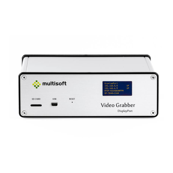
Page 7: Oled Screen
IP address of currently used NTP server Root distance to the currently used NTP server Dispersion – potential clock offset error due to the maximum uncorrected system clock frequency error Video Grabber DGR-1000 User Manual - v. 1.4 (FW 1.9) -
Page 8: Device Installation
(see figure below). Figure 5: Pass-through connection schema Computer is connected to the DGR-1000’s video input port, and the monitor is connected to the Video Grabber’s video output port. As a result Video Grabber effectively captures the video signal that is being sent by the computer to the monitor. -
Page 9: Monitor Emulation
Video Grabber. See the connection details below. Figure 7: Monitor emulation connection schema One of the computer’s video outputs is connected to the DGR-1000’s video input port while the other is connected to the monitor. When ‘Monitor emulation’ is enabled in the Video Grabber’s configuration it is detected by the computer as a monitor and as such can be configured as a mirror of an actual screen in the computer’s graphic card configuration. -
Page 10: Resolution Support
Please note that the rate at which the signal is captured will usually be much lower than the actual signal refresh rate. For details on setting the signal capture rate see 4.2.3 on page 29. Video Grabber DGR-1000 User Manual - v. 1.4 (FW 1.9) -
Page 11: Network Connection
3.5. Network connection Video Grabber DGR-1000 has two RJ45 ports, named LAN 1 and LAN 2. When both interfaces are configured and active (connected) then the same data is sent through both of them. This way two independent systems can receive the same data from the Video Grabber using two physically separate connections thus achieving redundancy. -
Page 12: Power Supply Unit
Due to the nature of DisplayPort connection when the Video Grabber locks to the recorded signal (e.g. when it starts) a short blink on the recorded display may be observed. Video Grabber uses 12V, 2.5A power supply, but its maximum power consumption is 12W. Video Grabber DGR-1000 User Manual - v. 1.4 (FW 1.9) -
Page 13: Video Grabber Web Interface
Video Grabber’s web interface should work with any reasonably modern web browser. It has been tested to work with: Internet Explorer 11, Microsoft Edge, Chrome 70 and Mozilla Firefox 60. Video Grabber DGR-1000 User Manual - v. 1.4 (FW 1.9) -
Page 14: Status Page
Status page is a default page of the Video Grabber’s web interface. It provides information current operational parameters of the Video Grabber device. This page is divided into 5 main sections: Figure 12: Video Grabber Status page. Video Grabber DGR-1000 User Manual - v. 1.4 (FW 1.9) -
Page 15: Device Status
Temperature of the CPU Temp. PCB Temperature measured on the main Printed Circuit Board (PCB) Table 2: Description of the parameters available in the Device status section of the Status page Video Grabber DGR-1000 User Manual - v. 1.4 (FW 1.9) -
Page 16: Power
Table 3: Description of the parameters available in the Power section of the Status page For the information on the identification of the power supply ports See 2.2, p. 6. Video Grabber DGR-1000 User Manual - v. 1.4 (FW 1.9) -
Page 17: Network
‘Down’ Network bridge Status of the Network bridge on the LAN interface Table 4: Description of the parameters available in the Network section on the Status page Video Grabber DGR-1000 User Manual - v. 1.4 (FW 1.9) -
Page 18: Video
Shown only when either SMB or NFS protocol is set See 4.1.4.3, p. 21 Table 5: Description of the subsections available in the Video section on the Status page Video Grabber DGR-1000 User Manual - v. 1.4 (FW 1.9) - Page 19 N / A – no signal is locked and captured Table 6: Descriptions of parameters available in the Signal subsection of the Video Section on the Status page Video Grabber DGR-1000 User Manual - v. 1.4 (FW 1.9)
- Page 20 Frequency of signal capture in Frames per Second (Frames per Second) Table 7: Descriptions of parameters available in the Output format subsection of the Video Section on the Status page Video Grabber DGR-1000 User Manual - v. 1.4 (FW 1.9)
- Page 21 Not mounted – filesystem is not mounted and is not accessible by the Video Grabber Table 8: Description of the parameters available in the Remote filesystems subsection in the Video section on the Status page Video Grabber DGR-1000 User Manual - v. 1.4 (FW 1.9)
-
Page 22: Ntp
Table 9: Description of information available in the NTP section on the Status page Consult NTP documentation (available e.g. on http://doc.ntp.org) for details on the algorithms used for time synchronization. Video Grabber DGR-1000 User Manual - v. 1.4 (FW 1.9) - Page 23 Difference between the reference time and the system clock (in seconds) Dispersion Magnitude of jitter between several time queries (in seconds) Table 10: Description of the parameters available in the NTP status table on the Status page Video Grabber DGR-1000 User Manual - v. 1.4 (FW 1.9)
-
Page 24: Configuration Page
See 4.2.3, p. 29 Time synchronization (NTP) related settings See 4.2.4, p. 42 Commands Command buttons See 4.2.5, p. 43 Table 11: Description of the sections available on the Configuration page Video Grabber DGR-1000 User Manual - v. 1.4 (FW 1.9) - Page 25 Figure 22: Configuration page in the Video Grabber web interface. Video Grabber DGR-1000 User Manual - v. 1.4 (FW 1.9)
-
Page 26: General
When checked the NTP related parameters will be shown on the on OLED device’s OLED screen Table 12: Description of the parameters available in the General section on the Configuration page Video Grabber DGR-1000 User Manual - v. 1.4 (FW 1.9) -
Page 27: Network
IPv4 netmask for the interface in the xxx.xxx.xxx.xxx format (e.g. 255.255.255.0). Prohibited values: 0.0.0.0 255.255.255.255 Table 13: Description of the parameters in the Interfaces subsection of the Network section on the Configuration page Video Grabber DGR-1000 User Manual - v. 1.4 (FW 1.9) - Page 28 For effective bridging one would have to configure connected Video Grabbers in the following way: bridge bridge Figure 26: Video Grabbers connected to networks A and B using network bridging Video Grabber DGR-1000 User Manual - v. 1.4 (FW 1.9)
-
Page 29: Video
– it is possible to fine tune the output provided by the Video Grabber. Figure 27: Output subsection in the Video section on the Configuration page Video Grabber DGR-1000 User Manual - v. 1.4 (FW 1.9) - Page 30 Only values from range <0.02; 120> are accepted. When set it will update also the FPM field. Table 15: Description of the parameters available in the Output subsection of the Video section on the Configuration page Video Grabber DGR-1000 User Manual - v. 1.4 (FW 1.9)
- Page 31 Allowed values: Integer <0; 2147483647> Example: Table 16: Description of the parameters available in the Protocol settings subsection of the Video section on the Configuration page Video Grabber DGR-1000 User Manual - v. 1.4 (FW 1.9)
- Page 32 Figure 29: Protocol settings subsection for SMB Output See the table below for the description of the required parameters. Identification numbers (first column) refer to the parameter’s position on the Figure 29. Video Grabber DGR-1000 User Manual - v. 1.4 (FW 1.9)
- Page 33 Table 18: SMB protocol settings description Video Grabber uses the same folder/file naming convention for SMB as it uses for NFS described in the previous section (See NFS protocol, p. 31). Video Grabber DGR-1000 User Manual - v. 1.4 (FW 1.9)
- Page 34 1. H.264 / LLE – contains parameter that is common for both H.264 and Lossless (LLE) 2. H.264 – contains parameters for H.264 3. Lossless (LLE) – contains parameters for Lossless (LLE) Video Grabber DGR-1000 User Manual - v. 1.4 (FW 1.9)
- Page 35 Integer <10;40000> Table 21: RTSP protocol settings for H.264 format In extreme situations – when screen contents change very fast – it may happen that P-Frames are actually bigger than I-Frames. Video Grabber DGR-1000 User Manual - v. 1.4 (FW 1.9)
- Page 36 (kbps) be used to avoid spikes on the network during the transmission. Allowed values: Integer >= Output rate and <10; 40000> Table 22: RTSP protocol settings for Lossless (LLE) format Video Grabber DGR-1000 User Manual - v. 1.4 (FW 1.9)
- Page 37 Figure 31: Sample configuration of Video Grabber saving PNG images on NFS share For this configuration to work user would also have to setup a NFS share (See 4.2.3.1, p.31). Video Grabber DGR-1000 User Manual - v. 1.4 (FW 1.9)
- Page 38 Figure 32: Sample configuration of Video Grabber saving JPEG images on the SMB share For this configuration to work user would also have to setup a SMB share (See 4.2.3.2, p.32) Video Grabber DGR-1000 User Manual - v. 1.4 (FW 1.9)
- Page 39 To connect to the configured H.264 stream user would have to use one of the RTSP connection strings that are shown in LAN 1 and LAN 2. In the sample shown above it would be either: rtsp://192.168.5.2/stream.264 rtsp://192.168.6.49/stream.264 Video Grabber DGR-1000 User Manual - v. 1.4 (FW 1.9)
- Page 40 To connect to the configured H.264 stream user would have to use one of the RTSP connection strings that are shown in LAN 1 and LAN 2. In the sample shown above it would be either: rtsp://192.168.5.2/stream.264 rtsp://192.168.6.49/stream.264 Video Grabber DGR-1000 User Manual - v. 1.4 (FW 1.9)
- Page 41 To connect to the configured LOSSLESS stream user would have to use one of the RTSP connection strings. In the sample shown above it would be either: rtsp://192.168.5.2/stream.lle rtsp://192.168.6.49/stream.lle Video parameters that refer to H.264 are not used when user connects to LOSSLESS stream. Video Grabber DGR-1000 User Manual - v. 1.4 (FW 1.9)
-
Page 42: Ntp
Integer >= minpoll and <4; 17> Clicking the button will update the Video Grabber’s time Update time using NTP. from NTP Table 23: Description of parameters available in the NTP section on the Configuration page Video Grabber DGR-1000 User Manual - v. 1.4 (FW 1.9) -
Page 43: Commands
See 6, p. 79 for details on Video Grabber firmware update procedure. Save Saves and applies settings currently set on the Configuration page. configuration Table 24: Description of the buttons available in the Commands section on the Configuration page Video Grabber DGR-1000 User Manual - v. 1.4 (FW 1.9) -
Page 44: Preview & Adjust Page
1. Preview – shows the preview of currently captured video stream. See 4.3.1, p. 45 2. Monitor emulation – contains options related to Monitor emulation. See 4.3.2, p. 46 3. EDID – contains options related to EDIDs. See 4.3.3, p. 47 Video Grabber DGR-1000 User Manual - v. 1.4 (FW 1.9) -
Page 45: Preview
Preview & Adjust page will not be shown. The browser will show previous page – result will be the same as if user clicked ‘Back’ button in the browser. Table 25: Description of buttons' functionalities. Video Grabber DGR-1000 User Manual - v. 1.4 (FW 1.9) -
Page 46: Monitor Emulation
(See 4.3.3, p. 47) Save Saves the configuration set on the Preview & Adjust page. Configuration Table 26: Description of options available in the Monitor emulation section of the Preview & Adjust page Video Grabber DGR-1000 User Manual - v. 1.4 (FW 1.9) -
Page 47: Edid
This option is only working if Video Grabber has non-default EDID data Drop EDID data Resets the EDID data to the default settings Table 27: Description of commands available in EDID section of the Preview & Adjust page Video Grabber DGR-1000 User Manual - v. 1.4 (FW 1.9) -
Page 48: Administration
Used to change credentials for access to www interface SNMP access Used to change credentials and security options of SNMP users Commands Contains an option to save changes Table 28: Description of sections in the Administration page Video Grabber DGR-1000 User Manual - v. 1.4 (FW 1.9) -
Page 49: Status Reporting
The value is in seconds so setting it to e.g. 5 will make the Video Grabber broadcast its status every 5 seconds. Setting it to 0 disables the reporting. Table 29: Description of Stat frame parameter on Administration page Video Grabber DGR-1000 User Manual - v. 1.4 (FW 1.9) -
Page 50: Www Access
Retype new Textbox for new password confirmation. password To avoid mistakes it is required to retype the new password in this box. Table 30: Description of WWW access related parameters. Video Grabber DGR-1000 User Manual - v. 1.4 (FW 1.9) -
Page 51: Snmp Access
Authentication password Password Allowed values: String of at least 8 characters Privacy Privacy password Password Allowed values: String of at least 8 characters Table 31: Description of SNMP access related parameters Video Grabber DGR-1000 User Manual - v. 1.4 (FW 1.9) -
Page 52: Commands
Figure 46: Commands section on the Administration page Button Description Save Button used to save and apply settings set on the Administration page. configuration Table 32: Description of button in the Commands section on the Administration page Video Grabber DGR-1000 User Manual - v. 1.4 (FW 1.9) -
Page 53: Snmp
While most actions do not require MIB files, there are some that do. For that reason 3 MIB files have been created: Video-Grabber Video-Grabber-Status Video-Grabber-Config To get the MIB files please contact support (support@multisoftsa.com). Video Grabber DGR-1000 User Manual - v. 1.4 (FW 1.9) -
Page 54: Read-Only User
Combining all the fields (notice that the field ‘subsection’ is empty as the object ‘serialNumber’ is not in any subsection) into one string gives the OID of the ‘serialNumber’ object: 1.3.6.1.4.1.46236.1.1.6.0 Video Grabber DGR-1000 User Manual - v. 1.4 (FW 1.9) -
Page 55: Read-Write User
Which will set the value to 44. The type is i, because we are setting integer value. Then to apply the new value one has to run the following command: snmpset -v3 –l authPriv –u rw_user -a MD5 –A uXTxzFQOscIZR1qcMAOSEwxf2HDeD6 -x DES –X LlUzFSpOVmBrem3VOFYfqd42VB1vve 192.168.5.2 1.3.6.1.4.1.46236.1.3.11.1.0 i 4321 Video Grabber DGR-1000 User Manual - v. 1.4 (FW 1.9) -
Page 56: Information (Section 1)
Table listing supported output formats Example: The OID for swBuild is 1.3.6.1.4.1.46236.1.1.5.0 as the OID is constructed in the following way: VIDEO GRABBER . SECTION . OBJECTNUMBER . 1.3.6.1.4.1.46236.1 . Video Grabber DGR-1000 User Manual - v. 1.4 (FW 1.9) -
Page 57: Status (Section 2)
Implemented revision marker (e.g. 201607130000Z) Example: The OID for staApiVersion is 1.3.6.1.4.1.46236.1.2.1.1.0 as the OID is constructed in the following way: VIDEO GRABBER . SECTION . SUBSECTION OBJECTNUMBER . 1.3.6.1.4.1.46236.1 . Video Grabber DGR-1000 User Manual - v. 1.4 (FW 1.9) -
Page 58: Stageneral (Subsection 2)
(enough power – at least 500mA) Example: The OID for uptime is 1.3.6.1.4.1.46236.1.2.2.1.0 as the OID is constructed in the following way: VIDEO GRABBER . SECTION . SUBSECTION OBJECTNUMBER . 1.3.6.1.4.1.46236.1 . Video Grabber DGR-1000 User Manual - v. 1.4 (FW 1.9) -
Page 59: Stavideo (Subsection 3)
Modeline – configuration line in xorg.conf (or file of similar function) that provides information to the display server about a connected display device that contains information on how to use it at a given resolution. Video Grabber DGR-1000 User Manual - v. 1.4 (FW 1.9) - Page 60 Number of I-frames on codec IFrames output Example: The OID for videoCodecFramesOut is 1.3.6.1.4.1.46236.1.2.3.18.0 as the OID is constructed in the following way: VIDEO GRABBER . SECTION . SUBSECTION OBJECTNUMBER . 1.3.6.1.4.1.46236.1 . Video Grabber DGR-1000 User Manual - v. 1.4 (FW 1.9)
-
Page 61: Stantp (Subsection 4)
There are dedicated tools used for SNMP table processing. Those tools require a MIB file containing information on table parsing. Video Grabber DGR-1000 User Manual - v. 1.4 (FW 1.9) - Page 62 Difference between local clock and remote server’s clock in seconds staNtpDispersion read-only String Maximum error of the local clock relative to the reference clock in seconds staNtpFlag read-only String NTP flag Video Grabber DGR-1000 User Manual - v. 1.4 (FW 1.9)
-
Page 63: Startsp (Subsection 5)
Protocol used: Type TCP or UDP rtspSession read-only Counter Number of bytes sent BytesOUT rtspSession read-only Counter Number of packets sent PacketsOut rtspSession read-only Integer Number seconds since Uptime session start Video Grabber DGR-1000 User Manual - v. 1.4 (FW 1.9) -
Page 64: Stafs (Subsection 6)
0 – disconnected 1 – connected Example: The OID for fs1Status is 1.3.6.1.4.1.46236.1.2.6.1.0 as the OID is constructed in the following way: VIDEO GRABBER . SECTION . SUBSECTION OBJECTNUMBER . 1.3.6.1.4.1.46236.1 . Video Grabber DGR-1000 User Manual - v. 1.4 (FW 1.9) -
Page 65: Configuration (Section 3)
Implemented revision marker (e.g. 201607130000Z) Example: The OID for staApiVersion is 1.3.6.1.4.1.46236.1.3.1.1.0 as the OID is constructed in the following way: VIDEO GRABBER . SECTION . SUBSECTION OBJECTNUMBER . 1.3.6.1.4.1.46236.1 . Video Grabber DGR-1000 User Manual - v. 1.4 (FW 1.9) -
Page 66: Confoutput (Subsection 2)
–v3 –l authPriv –u rw_user -a MD5 –A uXTxzFQOscIZR1qcMAOSEwxf2HDeD6 -x DES –X LlUzFSpOVmBrem3VOFYfqd42VB1vve 192.168.5.2 1.3.6.1.4.1.46236.1.3.11.1.0 i 4321 At this point the H264 stream becomes available under the following address: rtsp://192.168.66.40/stream.264 Video Grabber DGR-1000 User Manual - v. 1.4 (FW 1.9) -
Page 67: Confcodec (Subsection 3)
Once the settings are set one would have to apply them by running the following command: snmpset –v3 –l authPriv –u rw_user -a MD5 –A uXTxzFQOscIZR1qcMAOSEwxf2HDeD6 -x DES –X LlUzFSpOVmBrem3VOFYfqd42VB1vve 192.168.5.2 1.3.6.1.4.1.46236.1.3.11.1.0 i 4321 Video Grabber DGR-1000 User Manual - v. 1.4 (FW 1.9) - Page 68 FPS is lowered to keep bandwidth use below the limit. Min: 10 Max: 40000 Codec read- Enum Bitstream compatibility mode: LIBistreamCompat write 0 – specification 2.0 1 – specification 2.1 Video Grabber DGR-1000 User Manual - v. 1.4 (FW 1.9)
-
Page 69: Confcontrol (Subsection 4)
-x DES –X LlUzFSpOVmBrem3VOFYfqd42VB1vve 192.168.5.2 1.3.6.1.4.1.46236.1.3.4.2.0 i 1 Then apply the settings: snmpset –v3 –l authPriv –u rw_user -a MD5 –A uXTxzFQOscIZR1qcMAOSEwxf2HDeD6 -x DES –X LlUzFSpOVmBrem3VOFYfqd42VB1vve 192.168.5.2 1.3.6.1.4.1.46236.1.3.11.1.0 i 4321 Video Grabber DGR-1000 User Manual - v. 1.4 (FW 1.9) -
Page 70: Conflan (Subsection 5)
IP address of the LAN2 Ethernet IpAddress interface lan2 read-write String Netmask for the LAN2 Ethernet NetmaskAddress interface lan2 read-write String Gateway IP address for the LAN2 GatewayAddress Ethernet interface Video Grabber DGR-1000 User Manual - v. 1.4 (FW 1.9) - Page 71 -x DES –X LlUzFSpOVmBrem3VOFYfqd42VB1vve 192.168.5.2 1.3.6.1.4.1.46236.1.3.5.3.0 s “255.0.0.0” Then apply the settings: snmpset –v3 –l authPriv –u rw_user -a MD5 –A uXTxzFQOscIZR1qcMAOSEwxf2HDeD6 -x DES –X LlUzFSpOVmBrem3VOFYfqd42VB1vve 192.168.5.2 1.3.6.1.4.1.46236.1.3.11.1.0 i 4321 Video Grabber DGR-1000 User Manual - v. 1.4 (FW 1.9)
-
Page 72: Confnfs (Subsection 6)
String NFS2 share location in the Location following format: serverIP:/share e.g. 192.168.6.1:/pub nfs2 read-write Integer User id used within filesystem nfs2 read-write Integer Group id used within filesystem Video Grabber DGR-1000 User Manual - v. 1.4 (FW 1.9) -
Page 73: Confsmb (Subsection 7)
0 – auto 1 – smbv1 2 – smbv2 3 – smbv2.1 4 – smbv3 5 – smbv3.02 6 – smbv3.11 smb1 read-write Enum Samba (Windows share) domain Domain name. Video Grabber DGR-1000 User Manual - v. 1.4 (FW 1.9) - Page 74 0 – auto 1 – smbv1 2 – smbv2 3 – smbv2.1 4 – smbv3 5 – smbv3.02 6 – smbv3.11 smb2 read-write Enum Samba (Windows share) domain Domain name. Video Grabber DGR-1000 User Manual - v. 1.4 (FW 1.9)
-
Page 75: Confntp (Subsection 8)
0 – disabled 1 – enabled ntpMinPoll read-create Integer Minpoll value <4;17>, should be lower or same as maxpoll ntpMaxPoll read-create Integer Maxpoll value <4;17>, should be higher or same as minpoll Video Grabber DGR-1000 User Manual - v. 1.4 (FW 1.9) -
Page 76: Confedid (Subsection 9)
DDC, resets to 0 when done edidData read-write String Current EDID data, can be used to obtain monitor’s EDID (after successful read) or to load custom EDID. Write empty string to drop EDID data. Video Grabber DGR-1000 User Manual - v. 1.4 (FW 1.9) -
Page 77: Confupdate (Subsection 11)
-x DES –X LlUzFSpOVmBrem3VOFYfqd42VB1vve 192.168.5.2 1.3.6.1.4.1.46236.1.3.11.3.0 i 1 Then apply the settings: snmpset –v3 –l authPriv –u rw_user -a MD5 –A uXTxzFQOscIZR1qcMAOSEwxf2HDeD6 -x DES –X LlUzFSpOVmBrem3VOFYfqd42VB1vve 192.168.5.2 1.3.6.1.4.1.46236.1.3.11.1.0 i 4321 Video Grabber DGR-1000 User Manual - v. 1.4 (FW 1.9) -
Page 78: Confdpvideo (Subsection 12)
-x DES –X LlUzFSpOVmBrem3VOFYfqd42VB1vve 192.168.5.2 1.3.6.1.4.1.46236.1.3.12.1.0 i 1 Then apply the settings: snmpset –v3 –l authPriv –u rw_user -a MD5 –A uXTxzFQOscIZR1qcMAOSEwxf2HDeD6 -x DES –X LlUzFSpOVmBrem3VOFYfqd42VB1vve 192.168.5.2 1.3.6.1.4.1.46236.1.3.11.1.0 i 4321 Video Grabber DGR-1000 User Manual - v. 1.4 (FW 1.9) -
Page 79: Firmware Upgrade
4. At this point Video Grabber will restart and start the firmware upgrade. It will show a progress bar on its OLED screen and restart once the procedure is finished. Video Grabber DGR-1000 User Manual - v. 1.4 (FW 1.9) -
Page 80: Tftp Server
4. At this point Video Grabber will restart and start the firmware upgrade. It will show a progress bar on its OLED screen and restart once the procedure is finished. Video Grabber DGR-1000 User Manual - v. 1.4 (FW 1.9) -
Page 81: Factory Reset
5. When done Video Grabber will show the following message on the OLED screen: FACTORY RESET Remove the card! 6. Remove microSD card from the slot. At this point factory default settings should be restored and Video Grabber will reboot. Video Grabber DGR-1000 User Manual - v. 1.4 (FW 1.9) -
Page 82: Appendix A: Status Udp Frame Structure
0 – not locked, 1 - locked Unsigned char Not used Reserved for the future use Unsigned short HDR_CRC 16-bit CRC (crc16-ccitt) of this frame header, counted on all fields, except this one Video Grabber DGR-1000 User Manual - v. 1.4 (FW 1.9) -
Page 83: Appendix B: Broadcast Udp Packet Structure
VID_CRC control 0 – VID_CRC field is not used (filled with random values) 1 – VID_CRC field is used and filled with proper CRC data Not used For future use Video Grabber DGR-1000 User Manual - v. 1.4 (FW 1.9)
Need help?
Do you have a question about the DGR-1000 and is the answer not in the manual?
Questions and answers