
Related Manuals for Wasco OPTOIO-PCIe16 STANDARD

Summary of Contents for Wasco OPTOIO-PCIe16 STANDARD
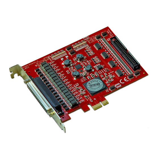
- Page 1 OPTOIO-PCIe16 STANDARD EDP No.: A-829200 16 optocoupler isolated digital inputs 16 optocoupler isolated digital outputs wasco ® user‘s guide...
- Page 2 ® © Copyright 2015 by Messcomp Datentechnik GmbH This documentation is copyright by Messcomp Datentechnik GmbH. All rights are reserved. Messcomp Datentechnik GmbH reserves the right to modify the products described in this manual at any time and without prior notice.
-
Page 3: Table Of Contents
8.1 Installation of the Windows driver ..............20 development files ...........20 ® 8.2 Installation of the Windows ® 8.3 Programming of the OPTOIO-PCIe16 by wasco driver ........23 8.4 Access to the board OPTOIO-PCIe16 ............24 Standard 8.5 Assignment of the Memory Mapped I/O addresses ..........24 8.5 Compatibility to the OPTOIO-PCI16... - Page 4 Programming ..............26 ® 9.1 Installing the Linux driver ...................26 9.2 Supported Linux-Distributions/Kernelversions .............26 ® 9.3 Programming the OPTOIO-PCIe16 with wasco driver ........26 9.4 Access to the OPTOIO-PCIe16 ..............27 Standard 9.5 Assignment of the Memory Mapped I/O addresses ..........27 10. Accessories ..................28 10.1 Fitting wasco...
-
Page 5: Description
® 1. Description The wasco ® interface card OPTOIO-PCIe16 provides 16 digital STANDARD inputs and 16 digital outputs with galvanic isolation, individually for each channel. Optocouplers of high quality ensure the potential separation for the inputs and outputs. All input optocouplers are bipolar. Special high power output optocouplers can handle a maximum switching current of up to 150 mA. -
Page 6: Installation Of Optoio-Pcie16
® 2. Installation of OPTOIO-PCIe16 STANDARD 2.1 How to install the card into your system Before you insert the card unplug the power cord or make sure, there is no current to/in the computer. Inserting in a running system may cause... -
Page 7: Connectors
® 3. Connectors 3.1 Position of the connector plugs CN1: Optocoupler Output OUT00...OUT15 CN2: Optocoupler Input IN00...IN15 OPTOIO-PCIe16 © 2015 by Messcomp Datentechnik GmbH EV05 STANDARD... -
Page 8: Pin Assignment Of Cn1
® 3.2 Pin assignment of CN1 OUT15- OUT15+ OUT14- OUT14+ OUT13- OUT13+ OUT12- OUT12+ OUT11- OUT11+ OUT10- OUT10+ OUT09- OUT09+ OUT08- OUT08+ OUT07- OUT07+ OUT06- OUT06+ OUT05- OUT05+ OUT04- OUT04+ OUT03- OUT03+ OUT02- OUT02+ OUT01- OUT01+ OUT00- OUT00+ Vcc: Connector for internal voltage source (+ 5V) (a wiring bridge must be soldered on L11), Never apply an external voltage across this pin. -
Page 9: Pin Assignment Of Cn2
® 3.3 Pin assignment of CN2 IN15- IN15+ IN14- IN14+ IN13- IN13+ IN12- IN12+ IN11- IN11+ IN10- IN10+ IN09- IN09+ IN08- IN08+ IN07- IN07+ IN06- IN06+ IN05- IN05+ IN04- IN04+ IN03- IN03+ IN02- IN02+ IN01- IN01+ IN00- IN00+ Vcc: Connector for internal voltage source (+ 5V) ( a wiring bridge must be soldered on L21), Never apply an external voltage across this pin. -
Page 10: Pin Assignment Of Cn2 On D-Sub37 Flat Ribbon Cable
® 3.4 Pin assignment of CN2 on D-Sub37 flat ribbon cable IN15- IN15+ IN14- IN14+ IN13- IN13+ IN12- IN12+ IN11- IN11+ IN10- IN10+ IN09- IN09+ IN08- IN08+ IN07- IN07+ IN06- IN06+ IN05- IN05+ IN04- IN04+ IN03- IN03+ IN02- IN02+... -
Page 11: System Components
® 4. System Components 4.1 Block diagram +12V +12V Steuer- Logik PCIe Bus Interface OPTOIO-PCIe16 © 2015 by Messcomp Datentechnik GmbH EV05 STANDARD... -
Page 12: Access To The System Components
The relevant addresses for OPTOIO-PCIe16 depend on the base address given by the BIOS. Access to the OPTOIO-PCIe16 is made by double word access only. For reasons of compatibility the wasco drivers handle or regard the lowest value bytes only. -
Page 13: Optocoupler Isolated Digital Inputs
® 5. 16 Optocoupler Isolated Digital Inputs The OPTOIO-PCIe16 provides 16 input channels which are opti- STANDARD cally isolated by optocouplers. The isolation voltage between GND and input is 500 V . The voltage within the input channels is limited to 50 5.1 Pin assignment of the input optocouplers... -
Page 14: Input Voltage Ranges
® 5.2 Input voltage ranges You can select two different input voltage ranges for each optocoupler input by setting jumpers on the blocks JP4, JP6, JP7 and JP8. JP7 JP8 JP4 JP6 OPTOIO-PCIe16 © 2015 by Messcomp Datentechnik GmbH... - Page 15 ® Following table shows the data of the two input voltage ranges: Jumper high closed 0...1 V 5...15 V 0...2 V 14...30 V IN00 IN05 IN08 IN13 IN01 IN06 IN09 IN14 IN02 IN07 IN10 IN15 IN03 IN11 IN04 IN12 Setting the jumper over Pin1 and Pin2 of the jumper block JP4 the input voltage range of IN00 changes from 0..2V (Low) and 14..30V (High) to...
-
Page 16: Input Circuitry
® 5.3 Input circuitry Jumper Optocoupler IN.. + Protection Diode IN.. - 5.4 Input current - 1,1V ≈ 3400Ω (Jumper off) - 1,1V ≈ (Jumper closed) 1000Ω OPTOIO-PCIe16 © 2015 by Messcomp Datentechnik GmbH EV05 STANDARD... -
Page 17: Optically Isolated Outputs
® 6. 16 Optically Isolated Outputs The OPTOIO-PCIe16 provides 16 output channels, which are gal- STANDARD vanically isolated by optocouplers. The isolation voltage between GND and output ist 500 V 6.1 Pin assignment of the output optocouplers 6.2 Optocoupler specifications Voltage collector-emitter: max. -
Page 18: Board Configuration
® 7. Board Configuration 7.1 Board Identification The board Identification enables you to dif- Jumper ferentiate between several PC boards of the same type in your system. This is realised by a software readable jumper block. The board identication to be read consists of one Byte (8 Bit) and is struc-... -
Page 19: Access With 8 Or 32 Bit
® 7.2 Access with 8 or 32 Bit The jumper block JP10/1-2 enables you to set the data width of the access. If the jumper block JP10/1-2 is not set (Default) the card works in compa- tibility mode. In this mode the card is accessed in 8-bit mode. Additionally,... -
Page 20: Windows ® Programming
® ® 8. Windows Programming ® 8.1 Installation of the Windows driver ® To apply the card under Windows a special driver has to be installed, which enables access to the card. ® After starting-up Windows 10, 8 und 7 your operating system automati- cally registers a new hardware device to be found. - Page 21 ® Having installed driver software and development files competely, your system control panel shows an icon for the localisation of all wasco ® and PCIe cards existing in the system. OPTOIO-PCIe16 © 2015 by Messcomp Datentechnik GmbH EV05 STANDARD...
- Page 22 ® ® Start the card‘s monitoring by double-clicking the "wasco " icon. Follow- ing screen appears (in this example an OPTOIO-PCIe16 may be STANDARD used) Once the system detected the card, this window shows card name, board ID, I/O address and possible interrupt number for each card. Furthermore the tab „Information“...
-
Page 23: Programming Of The Optoio-Pcie16 By Wasco Driver
After having installed Kithara‘s development files by means of the se- tup program the folder wasco contains of the relevant development files and program samples. More program samples specified for access to the OPTOIO-PCIe16 you can find on the enclosed CD or please visit our Website. -
Page 24: Access To The Board Optoio-Pcie16
® 8.4 Access to the board OPTOIO-PCIe16 Standard The access to the OPTOIO-PCIe16 is done exclusively via the board Standard name (type of card) OPTOIO-PCIe16/standard. 8.5 Assignment of the Memory Mapped I/O addresses The Memory Mapped I/O addresses of the single hardware components... -
Page 25: Standard
® 8.5 Compatibility to the OPTOIO-PCI16 STANDARD Developping OPTOIO-PCIe16 and its drivers special regard was STANDARD attended to use identical accesses as to OPTOIO-PCI16 . This STANDARD enables you to switch from PCI to PCIe in existing programs in a very easy way. -
Page 26: Linux ® Programming
® ® 9. Linux Programming , you can find a Linux wasco ® ® To use the board with Linux driver on the CD provided or on our website. This is in code form and therefore can be changed and customized by the customer at any time. -
Page 27: Access To The Optoio-Pcie16
® 9.4 Access to the OPTOIO-PCIe16 Standard The access to the OPTOIO-PCIe16 is done exclusively via the board Standard name (type of card) OPTOIO-PCIe16/standard. 9.5 Assignment of the Memory Mapped I/O addresses The Memory Mapped I/O addresses of the single hardware components... -
Page 28: Accessories
® 10. Accessories 10.1 Fitting wasco ® accessories Connecting parts EDP no. PDB37F23PB40 connector laying set A-497500 DS37R100DS37 Connecting cable A-202200 DS37R200DS37 Connecting cable A-202400 DS37R500DS37 Connecting cable A-202800 KMDB-37S Screw Terminal block(without perfboard) A-204910 KMDB-37 Screw Terminal block (with perfboard for... -
Page 29: Single Components For Customer Assembly
® DS37R...* PDB37F23PB40 XMOD SSR4 DS37R...* KMDB-37** XMOD SSR4 XMOD REL-8 OPTOIO-PCIe16 STANDARD * DS37R100DS37 or DS37R200DS37 or DS37R500DS37 ** or KMDB-37S (without hole grid for soldering) 10.3 Single components for customer assembly Connection parts EDP no. D-Sub plug 37 pin for solder connection... -
Page 30: Troubleshooting
Please check all settings of your computer or contact your system administrator. (Since these are BIOS settings we cannot expand on this issue. We point to your computer‘s system user‘s guide) Did you install the latest driver version for the wasco ® drivers? Updates you can find here: http://www.messcomp.com OPTOIO-PCIe16 ©... -
Page 31: Specifications
® 12. Specifications Optocoupler Inputs Optocoupler: LTV-244 or compatible 16 channels, optically isolated Galvanic isolation also between every single channel with each two separate connections Overvoltage protection by protection diodes Two different input voltage ranges selectable by jumpers: Range 1 high = 14..30 Volt... -
Page 32: Product Liability Act
® 13. Product Liability Act Information for Product Liability The Product Liability Act (Act on Liability for Defective Products - Prod- HaftG) in Germany regulates the manufacturer‘s liability for damages caused by defective products. The obligation to pay compensation can already be given, if the product’s... - Page 33 ® * unplug the power plug before you open ta device or make sure, that there is no current to/in the device. * You only may start up any components, boards or devices, if they have been installed in a secure touch-protected casing before. During installa- tion they must be de-energized.
-
Page 34: Ec Declaration Of Conformity
® 14. EC Declaration of Conformity This is to certify, that the following product with CE marking OPTOIO-PCIe16 STANDARD EDP number A-829200 comply with the requirements of the relevant EMC directives 2014/30/ EU. This declaration will lose its validity, if the instructions given in this manual for the intended use of the products are not fully complied with. - Page 35 ® Reference system for intended use This PC expansion board is not a stand-alone device. The CE-conform- ity only can be assessed when using additional computer components simultaneously. Therefore, the CE conformity only can be confirmed when using the following reference system for the intended use of the...
Need help?
Do you have a question about the OPTOIO-PCIe16 STANDARD and is the answer not in the manual?
Questions and answers