Table of Contents
Advertisement
Quick Links
Advertisement
Table of Contents

Related Manuals for AEP transducers DYNAMIC STAR


Summary of Contents for AEP transducers DYNAMIC STAR
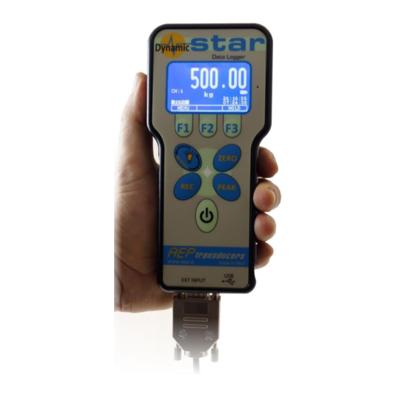
- Page 1 ✓ Weight ✓ Force ✓ Torque ✓ Angular ✓ Velocity ✓ Power ✓ Pressure ✓ Displacement FAST ACQUISITION PROFESSIONAL HANDHELD INDICATOR USER GUIDE MO.DYNAMIC STAR.R3.EN 41126 Cognento (MODENA) Italy Via Bottego 33/A Tel:+39-(0)59-346441 Fax:+39-(0)59-346437 E-mail: aep@aep.it...
- Page 2 41. CANNECTION FOR TRIGGER HW 42. CONNECTION OF INCREMENTAL ENCODER AEP transducers holds the right to make any change when necessary, without notice. The data contained in this manual are just indicative and the manufacturer declines any responsibility for errors or discrepancies with respect to this manual Pag.
-
Page 3: Declaration Of Conformity
Manufacter: AEP transducers s.r.l Address: Via Bottego 33/A 41126 Cognento MODENA (Italia) DECLARES THAT THE FOLLOWING PRODUCT Product Name: DYNAMIC STAR Type: FAST ACQUISITION PROFESSIONAL HANDHELD INDICATOR Year of Construction: 2015 Options: this declaration covers all the options specified in the manual. - Page 4 REC. DYNAMIC STAR can store acquisition points at maximum speed 19,200kHz for a time of about 13s. The storage can be affected by a trigger HW or SW to better define the time interval of the test. The measurements are stored in non-volatile memory, which retains data even when the power down.
- Page 5 DYNAMIC STAR USER GUIDE MO.DYNAMIC STAR.R3.EN 7. AVAILABLE FITTINGS FORCE and WEIGHT measurements using load cells or force transducers in compression and tension in the range from 10N (1kg) to 500t (5000kN). Second channel with INCREMENTAL ENCODER input (rotary or linear) used for measures of DISPLACEMENT, LENGTH or SPEED.
-
Page 6: Technical Data
DYNAMIC STAR USER GUIDE MO.DYNAMIC STAR.R3.EN 9. TECHNICAL DATA STRAIN GAUGE INPUT STANDARD MEASUREMENT INPUT ±2 mV/V RESOLUTION (@± 2mV/V - Filter 0) ± 200.000 div ± 150.000 div ± 100.000 div ± 80.000 div ± 65.000 div ± 50.000 div ±... - Page 7 DYNAMIC STAR USER GUIDE MO.DYNAMIC STAR.R3.EN 14400 Hz 18.5s ---------- 7200 Hz 18.5s 4800 Hz 27.5s 2400 Hz 110s 1200 Hz 220s 110s 10min 5min 45min 22.5min 1h e 13min 36min 1h e 30min 45min 3h e 40min 1h e 50min...
-
Page 8: Software Applications
DYNAMIC STAR and support the user in the various functions of calibration, testing, analysis, data storage, transfer of measures on Microsoft Excel etc..WINSTAR is a software dedicated to DYNAMIC STAR. Through this software you can download the data logger and operate directly on DYNAMIC STAR to change parameters and create graphics test. -
Page 9: Maintenance
To avoid that there may be inadvertent shutdowns of the instrument during a Data Logger cycle the button is disabled when a datalog is active. Therefore in case should be necessary to turn off DYNAMIC STAR during a data logger cycle you must first stop the Data Logger (hold REC button for 4 seconds). -
Page 10: Power Measurement
In reverse mode, the display of the main page will appear as shown below. 17. POWER MEASUREMENT DYNAMIC STAR can measure at the same time the force and the speed through an incremental encoder. So it is suitable for the measurement of mechanical power for both linear and rotary systems. - Page 11 Example 3. The value to be displayed consists of 9 digits. The value cannot be displayed. It is given the error message HHHHHHHH. Depending on the configuration on the main page DYNAMIC STAR may appear several icons that describe the functional status of the instrument.
-
Page 12: Zero Function
LOW BATTERY If this message appear please recharge the battery immediately. If this condition persist for more than 2 minutes DYNAMIC STAR will be automatically turned off. 19. ZERO FUNCTION The ZERO funcion is activated by the dedicated key ZERO and it is used to clear the indication of the strain gauge and the encoder channels. -
Page 13: Peak Function
MO.DYNAMIC STAR.R3.EN 20. PEAK FUNCTION The PEAK function is used to display the maximum (PEAK +) or minimum (PEAK-) of a dynamic measurement. DYNAMIC STAR allows to select the function PEAK+ o PEAK-. The icon PEAK+ PEAK- on the display shows which PEAK is active. -
Page 14: Data Logger Function
0.1s to 1 point every 30 minutes. The internal memory of DYNAMIC STAR allows you to store up to 266,000 measurement points if you only use the channel strain gauge or up to 133,000 measurement points if you also use the encoder channel. - Page 15 DYNAMIC STAR USER GUIDE MO.DYNAMIC STAR.R3.EN As an alternative to storage at precise time intervals there is the MANUAL storage. In the case of MANUAL storage a point is stored with each press of the button. In this mode and if the PEAK mode is active, it is stored the PEAK value detected instead of the current real time measure.
- Page 16 The value fields are parameters where you have to enter the value using the keys and that allow to increase/decrease the value. The choice field are parameters where the valid values are proposed directly by DYNAMIC STAR. Scroll the proposed values with and until you find the desired value.
-
Page 17: Channel Setup
(2) mV/V uniti is useful to check the transducer output in a not engineering unit to verify the real electric signal in input (3) The selection of the unit select if DYNAMIC STAR will compute a position value o a speed value. - Page 18 DYNAMIC STAR has got two parameters to save the battery charge. POWER OFF makes it possible to set a AUTO POWER OFF time from 1 to 99 minutes. DYNAMIC STAR will go off at the set time if no button is pressed during this period.
-
Page 19: Data Logger
DYNAMIC STAR USER GUIDE MO.DYNAMIC STAR.R3.EN $XXXXXXXX;YYYYYYYY<cr> with the encoder enabled where: $ = 1 character = start of message XXXXXXXX : 8 characters : real time value of the strain gauge channel (sign and point position are included) YYYYYYYY : 8 characters : real time value of the encoder channel (sign and point position are included) <cr>... - Page 20 FILTER greater than 0) it is possible to obtain better accuracy at the expense of the settling time (see the table below relative to the answer to a normalized signal step). After having acquired a value to the set acquisition frequency DYNAMIC STAR applies a digital filter (type moving average). The number of samples used is determined by the parameter FILTER.
- Page 21 DYNAMIC STAR USER GUIDE MO.DYNAMIC STAR.R3.EN Filtro 0: NO Filter (max speed) Filtro 1: 2 samples Filtro 2: 4 samples Filtro 3: 8 samples Filtro 4: 16 samples Filtro 5: 32 samples To compute the cutoff frequency (at -3dB) of the digital filter it is necessary to keep in count both the acquisition frequency and the number of samples used.
- Page 22 DYNAMIC STAR USER GUIDE MO.DYNAMIC STAR.R3.EN Fig 1 : Effect on the measure due to different Acquisition Frequency Figura 2 : Effect on the measure due to different filter Pag. 21...
- Page 23 DYNAMIC STAR USER GUIDE MO.DYNAMIC STAR.R3.EN ADJUSTMENT OF FILTERS IN TORQUE WRENCH AND SCREWDRIVER SETTINGS For calibration in screwdrivers and handheld torque tools mode, it is recommended to use one of the available digital filters, corresponding to different acquisition frequencies.
-
Page 24: Date And Time
DYNAMIC STAR USER GUIDE MO.DYNAMIC STAR.R3.EN 28. PEAK PARAMETERS P E A K P A R A M E T E R FIRST PEAK ENABLE : NO PEAK THRESH (%FS) : 02 AUTO RESET : SI AUTO RESET TIME : 05... -
Page 25: View Log
To return to the main menu press ENTER. 31. SERVICE The selection SERVICE within the programming menu allows you to access password-protected pages dedicated to AEP transducers or calibration pages of channels whose passwords are provided in this manual. Enter the security password to access the selected page, and press ENTER. -
Page 26: Usb Communication Protocol
<cr>: carriage return: command terminator = 13 = 0xD DYNAMIC STAR on receipt of a valid command responds with a message that is different from time to time for content and format. The response of DYNAMIC STAR is in binary format and variable length depending on the type of the command. - Page 27 DYNAMIC STAR USER GUIDE MO.DYNAMIC STAR.R3.EN Format of DYNAMIC STAR answer to a valid command (N = number of bytes of response for a given command in function of the code SYNC) BYTE N. Comment SYNC B7.. B4 identify the SYNC code . B7 is always set to 1...
- Page 28 DYNAMIC STAR USER GUIDE MO.DYNAMIC STAR.R3.EN Alternatively it is used to request a specific data related to a channel (eg FULL SCALE). In this case the number of bytes in the response is 6. BYTE N. BIT 7 BIT6 BIT5...
-
Page 29: Software Examples
DYNAMIC STAR USER GUIDE MO.DYNAMIC STAR.R3.EN 33. SOFTWARE EXAMPLES The following C and Visual Basic code explain how to decode the data packet Example in C RxBuffer is the incoming serial buffer. Indice is the index of RxBuffer array that contains the SYNC code... -
Page 30: Read Commands
READ COMMAND: Read actual values Command : $C000000000000<cr> Answer from DYNAMIC STAR: 11 byte with encoder enabled : 6 bytes with encoder disabled : SYNC = 8 The real time values of the strain gauge and encoder channels are transmitted... -
Page 31: Write Commands
Byte 7 .. 14 : 8 ASCII characters with the software versione. Example: ‘Ver: 1.0’ 35. WRITE COMMANDS Write commands allow you to modify the DYNAMIC STAR parameters They typically have an answer according to SYNC 10 with the indication of whether the command was correctly accepted. - Page 32 DYNAMIC STAR USER GUIDE MO.DYNAMIC STAR.R3.EN WRITE COMMAND: Set Digital Filter Command: $L20000000000X<cr> Answer: 4 bytes : SYNC = 10 ‘X’ = 1 ASCII character: Digital Filter value ‘0’..’5’ WRITE COMMAND: Set Unit for the Strain Gauge Channel Command: $L3000000000XX<cr>...
- Page 33 USER GUIDE MO.DYNAMIC STAR.R3.EN 36. COMMUNICATION CONTINUOUS MODE The communication protocol described so far is expected to get a measure from DYNAMIC STAR as an answer to the command $C00000000000<cr>. This type of protocol is obviously slow. DYNAMIC STAR is capable of transmitting values in continuous mode (ie without the need to send a transmission command) up to...
- Page 34 DYNAMIC STAR USER GUIDE MO.DYNAMIC STAR.R3.EN 37. COMMAND FOR DATA LOGGER READ COMMAND: READ DATALOGGER SETTING Command: $D000000000000<cr> Answer: 15 bytes : SYNC = 9 Byte 0 : 0x90 Byte 1 : ‘D’ Byte 2 : ‘0’ Byte 3 : 0 Byte 4: binary value : acquisition interval 0=>...
- Page 35 You can not run a download with a datalog cycle in progress. This condition can be monitored with the command Read Actual Value A download cycle begins with a command of StartDownload and ends with a command AbortDownload or when DYNAMIC STAR has no more data to send .
- Page 36 In the case of manual acqusizioni time it is included in the data packet Start Download Command. Command: $D700000000000<cr> Answer: 45 bytes : SYNC = 13 DYNAMIC STAR answer with SYNC 13. Abort Download Command. Command: $D800000000000<cr> Answer 4 bytes : SYNC = 10 Abort the current download Pag.
- Page 37 Linear encoder : sensibility is the step resolution and its unit (mm-m-foot-inch-cm-dm-um) Angular encoder : sensibility is the number of step for revolution. In both cases it must be taken in count that DYNAMIC STAR perform a x4 multiply of the pulses. Pag. 36...
- Page 38 For the automatic identification of different transducers it is necessary to make a code on the connector using the lines CODE 0, CODE 1, CODE 2 and COMMON according to the Table 5. In case of just one transducers it is not necessary to make any cabling code. DYNAMIC STAR in this case set the external transducer Pin 6 : COMMON...
-
Page 39: Incremental Encoder Connection
Note : It is necessary to power supply the encoder from an external +5Vdc power supply. DYNAMIC STAR has an 5Vdc output but it is rated just for 10mA. Normally this current it is not enough for optical incremental encoder.
Need help?
Do you have a question about the DYNAMIC STAR and is the answer not in the manual?
Questions and answers