Advertisement
OPERATING INSTRUCTIONS FOR SHP400 USERS
OPERATION
OPERATION
3)
1) Remove the stump grinder from its carrying
1) Remove the garden tiller
vehicle or trailer. ALWAYS USE CAUTION
1) Remove the garden tiller
a.
Move the fuel valve
from its trailer/carrier. Use caution.
2) Familiarize yourself with this stump grinder
lever to ON
from its trailer/carrier. Use caution.
aution.
and its controls. Learn where all engine controls
position.
2) Familiarize yourself with the machine and its
are and be prepared to stop this machine quickly
2) Familiarize yourself with the machine and its
b.
To start a cold
controls.
in case of emergency.
machine and its
controls.
engine, move the
3) PPE (PErSONAL PrOTECTION EqUIPmENT)
OPERATION OF GT622
3) Ensure the safety clutch control lever is in the
choke lever or choke
3) Ensure the safety clutch control lever is in the
IS mANdATOrY bEfOrE OPErATINg ThIS
disengaged position. The safety clutch
rod (applicable
disengaged position. The safety clutch
mAChINE. Wear safety glasses or helmet and visor
types) to the
control lever is located on the left handle bar.
trol lever is in the
combination, loose fitting gloves, hearing protection,
control lever is located on the left handle bar.
1) Remove the garden tiller
CLOSED
The disengaged position of the lever is down.
and steel caps boots when operating this machine.
e safety clutch
The disengaged position of the lever is down.
from its trailer/carrier/ute. Use caution.
position.
4) Move choke control to Choke or Start position:
4) Remove the shaft locking pin located behind
e left handle bar.
To restart a
4) Remove the shaft locking pin located behind
NOTE: ChOKE mUST fULLY CLOSE. mOVE
2) Familiarize yourself with the machine and its
the wheel axle. Store pin in hole provided on
warm engine,
ThrOTTLE CONTrOL TO rUN Or fAST
the wheel axle. Store pin in hole provided on
he lever is down.
controls.
leave the choke lever or choke rod in the OPEN position.
left hand side of handle bar.
POSTION. TUrN KEY TO "ON" POSITION.
left hand side of handle bar.
STArT mAChINE. ChOKE CONTrOL
c.
Move the
n located behind
5) The wheel axle will now pivot. Lift up on the
3) Adjust wheels if required, using the handle wheel
5) The wheel axle will now pivot. Lift up on the
ShOULd ONLY bE USEd fOr COLd STArTS.
throttle lever
adjustment lever.
handle to allow wheel axle to pivot. For
hole provided on
5) Manoeuvre the stump grinder to the area where
handle to allow wheel axle to pivot. For
away from the
transport, keep the wheel axle forward. When
the stump is to be removed. This can be done by
MIN position,
transport, keep the wheel axle forward. When
4)
Adjust depth shoe if required, using the depth
cultivating, keep the wheel axle rearward for
pushing the stump grinder using the free wheeling
about 1/3 of the
cultivating, keep the wheel axle rearward for
control adjustment lever.
feature, or driving the machine using its own power.
added stability and control.
way toward the
added stability and control.
ot. Lift up on the
6) Position the stump grinder so that the grinding disc
MAX position.
DO NOT transport the tiller with the wheel
5) Ensure the tyne engagement control lever is in
DO NOT transport the tiller with the wheel
is just over the front edge of the stump.
le to pivot. For
axle in the rear position.
the neutral position. The tyne engagement
axle in the rear position.
d.
Turning the engine switch
7) Release the spring loaded pin located behind
control lever is located
on the left hand side of the
le forward. When
6) Adjust depth shoe (if equipped) by removing
to the ON position.
and at the base of the handle bar, this is the
6) Adjust depth shoe (if equipped) by removing
machine below handle bar. The neutral position
shaft locking collar and sliding depth shoe to
handle release pin. Place the handle bar into the
axle rearward for
shaft locking collar and sliding depth shoe to
of the lever is achieved by simply releasing the
RECOIL STARTER
position that best suits to operator and secure the
desired position. Replace shaft locking collar.
desired position. Replace shaft locking collar.
Pull the starter grip lightly
tyne engagement control lever.
locking pin.
until you feel resistance,
7)
Open fuel shut-off valve. Set choke
r with the wheel
8) Release the spring loaded swivel locking pin
7)
Open fuel shut-off valve. Set choke
then pull briskly.
6)
control to Choke or Start position.
Open fuel shut-off valve. Set choke
located on the main body right behind the engine,
control to Choke or Start position.
Return the starter
this is the main body release pin. This will allow the
Set throttle control to Run or Fast
control to Choke or Start position.
Set throttle control to Run or Fast
grip gently.
stump grinder to pivot over center.
position. Set engine
Set throttle control to Run or Fast
position. Set engine
ped) by removing
9) You should now be in position at the stump
4)
stop switch to On or
position. Set engine
stop switch to On or
and ready to start grinding. Slowly increase the
ng depth shoe to
stop switch to On or
Run position. Pull
a.
Run position. Pull
Start and warm up engine.
operating RPM of the engine to approximately 2000
starter cord rapidly.
Run position. Pull
aft locking collar.
RPM and activate the clutch engagement switch
starter cord rapidly.
b.
Put Wheel Drive Control Lever in neutral.
Repeat (if necessary)
starter cord rapidly.
to on. This will engage the grinding disc. mAKE
Repeat (if necessary)
c.
One wheel hub may be disengaged (free wheeling)
with choke off.
Repeat (if necessary)
SUrE ThAT ThE grINdINg dISC dOES NOT
alve. Set choke
with choke off.
for easier steering before driving machine to work
mAKE CONTACT WITh ThE STUmP bEfOrE
with choke off.
Start position.
8) When in position to begin garden tilling,
loccation. (See Wheel Hub Feature)
ENgAgINg ThE CLUTCh. Operate the engine at
8) When in position to begin garden tilling,
engage the safety clutch control lever. The
d.
Squeeze the safety Clutch Lever/Operator Presence
maximum RPM.
o Run or Fast
7) When in position to begin garden tilling,
engage the safety clutch control lever. The
Control and change the Wheel Direction Control to
tynes will begin rotating. Wheel axle must be in
10) Slowly lower the stump grinder until the grinding disc
pull up on the tyne engagement control lever.
tynes will begin rotating. Wheel axle must be in
desired speed and direction.
the rear position while tilling. Release the
comes in contact with the stump. Pivot, slew, or oscillate
The tynes will begin to turn. Release the tyne
the rear position while tilling. Release the
the stump grinder from left to right in a long slow
e.
Adjust the wheel speed and navigate the trencher to the
safety clutch control lever to stop the tynes
engagement control lever to stop the tynes turning.
safety clutch control lever to stop the tynes
sweeping motion. Maintain the same elevation until
starting position. The trencher is designed to dig toward
rotating. Tyne speed is governed by engine
Tyne speed is governed by engine throttle setting.
rotating. Tyne speed is governed by engine
the front section of the stump has been removed, then
the operator (with the Wheel drive Control Lever in
throttle setting.
throttle setting.
move the machine forward lower the stump grinder and
reverse). With this in mind, position the machine to
repeat the process to remove the next section.
start the trench. Note: When initially engagaing the
8) Do not hurry the job. Proceed slowly and allow
WARNING! – KEEP HANDS AND
rotating chain into the ground, be aware that in the hard or
11) Precision control at the stump can be achieved by
WARNING! – KEEP HANDS AND
the machine time to do the job. When ground
FEET CLEAR OF TYNES AT ALL
rocky ground the rotating trencher chain may
operating the wheel control levers for each wheel
FEET CLEAR OF TYNES AT ALL
is extremely hard, reduce engine speed. Consider
TIMES!
aggressively dig in and lurch forward. For this reason
effectively and efficiently. Alternate between the
TIMES!
watering the surface and reducing engine speed.
make sure that theres is sufficient clearance from
two wheels by effectively crabbing, alternating the
n garden tilling,
Adjust wheels and depth shoe accordingly while
wheels from left to right in order to cover the entire
structures, objects or people in front of the machine.
ontrol lever. The
width of the stump, and any surface roots.
tilling
9) Do not hurry the job. Proceed slowly and allow
9) Do not hurry the job. Proceed slowly and allow
9) Do not hurry the job. Proceed slowly and allow
5)
the machine time to do the job. When ground
the machine time to do the job. When ground
NOTE: The constant build up of grinding debris
the machine time to do the job. When ground
is extremely hard, reduce engine speed.
Make sure that there is sufficient clearance from
may inhibit the stump grinder from performing
is extremely hard, reduce engine speed.
is extremely hard, reduce engine speed.
effectively. To help insure safe, effective, and
structures, objects or people in front of the machine
efficient working results, keep the working area
a.
Put Wheel Drive Lever in neutral.
WARNING! – IN CASE OF DIFFICULTY,
raked level and free of grinding debris. ALWAYS
b.
Be sure both hubs are engaged (turn hub lock handle
USE A rAKE.
clockwise). (See Free Wheel Hub Feature)
DISENGAGE THE SAFETY CLUTCH
mAKE SUrE grINdINg dISC hAS STOPPEd
c.
Have engine at full throttle (forward).
CONTROL LEVER. ALL TILLING ACTION
COmPLETELY bEfOrE CLEArINg dEbrIS
d.
Hold Digging Chain Control Lever in On position.
12) After the front part of the stump has been removed
e.
Squeeze the safety Clutch Lever/Operator Presence Control.
STOPS. Press the engine "STOP" button
continue to advance the stump grinder forward
f.
Slowly lower the digging boom until the desired trench
10) Stop Engine: Release the safety clutch control
located on the engine.
10) Stop Engine: Release the safety clutch control
repeating the left to right motion until the entire
depth is achieved using the Digging Boom Control Lever.
lever. Move throttle to Slow position. Set engine
stump has been removed. ALWAYS bE ALErT
lever. Move throttle to Slow position. Set engine
g.
Put Wheel Drive Control Lever in reverse. Start at low speed.
stop switch to Stop or Off position. DO NOT move
TO fOrEIgN ObJECTS ThAT ArE bUrIEd IN ThE
stop switch to Stop or Off position. DO NOT move
h.
Adjust the wheel speed until a workable speed is reached
10) Stop Engine: Release the safety clutch control
choke control to Choke
STUmP: WIrE, PIPE, STAr PICKETS, Or mETAL
choke control to Choke
Use a very slow speed for trenching and adjust for soil
STAKES. NOTE: fOr bETTEr PErfOrmANCE ANd
or Start position to stop
lever. Move throttle to Slow position. Set engine
conditions as necessary. If objects such as rocks or roots
or Start position to stop
TO AVOId EXCESSIVE CLUTCh WEAr, OPErATE ThE
engine. Backfire or
jam in the chain, release the Safety Clutch Lever/Operator
engine. Backfire or
stop switch to Stop or Off position. DO NOT move
ENgINE AT fULL ThrOTTLE dUrINg OPErATION.
engine damage may
Presence Control, then reverse the chain to dislodge the
9) Stop Engine: Release the tyne engagement
engine damage may
WARNING: KEEP hANdS ANd fEET CLEAr Of ThE
choke control to Choke
debris. If necessary move the trencher forward a few
occur.
grINdINg ZONE ANd OThEr mOVINg PArTS WhILE
control lever. Move throttle to Slow position.
occur.
inches and trench the area again.
or Start position to stop
ThE ENgINE IS rUNNINg.
Set engine stop switch to Stop or Off position.
AFTER USE
13) dO NOT LEAVE ThE mAChINE UNATTENdEd
AFTER USE
DO NOT move choke
engine. Backfire or
WhILE ThE ENgINE IS rUNNINg.
control to Choke or Start
engine damage may
1)
14) After the stump has been removed use the throttle
position to stop engine.
1)
control to gradually decrease the engine RPM's,
occur.
Backfire or engine
TUrN ThE CLUTCh ENgAgEmENT SWITCh
damage may occur.
2) Allow machine to cool down.
TO Off. Make sure that the grinding disc has
2) Allow machine to cool down.
come to a complete stop before moving the stump
AFTER USE
3) Wash mud and dirt off of the garden tiller.
grinder.
3) Wash mud and dirt off of the garden tiller.
AFTER USE
6)
Ensure no water enters the carburettor.
15) STOP ENgINE: Do not move the choke control to
Ensure no water enters the carburettor.
Shut off switch on
the CHOKE position to stop the engine. Backfire or
1)
Turn fuel shut off valve to the "OFF"
4) Remove any weeds, wire, rope or other
console should be
4) Remove any weeds, wire, rope or other
engine damage may occur.
1)
material that may have wrapped around the
used, not shut off
position.
material that may have wrapped around the
16) Move throttle control to the slow position
switch on engine.
tynes and rotor assembly.
tynes and rotor assembly.
17) Turn the key to the off position and allow the machine
a.
Move the throttle lever
2) Allow machine to cool down.
2) Allow machine to cool down.
to cool down.
5) Return wheel axle to forward position for
to the MIN position.
5) Return wheel axle to forward position for
AFTER USE
3) Wash mud and dirt off of the garden tiller.
transport. Replace shaft locking collar.
Some engine applications use a
transport. Replace shaft locking collar.
3) Wash mud and dirt off of the garden tiller.
remote-mounted throttle control
Ensure no water enters the carburettor.
6) Return depth shoe (if equipped) to full Up
1) Allow the machine to cool down.
6) Return depth shoe (if equipped) to full Up
rather than the engine-
Ensure no water enters the carburettor.
2) Keep the machine clean using warm soapy water.
4) Remove any weeds, wire, rope or other
position.
mounted lever shown here
position.
Make sure that no water enters the carburetor
material that may have wrapped around the
b.
Turn the engine switch
4) Remove any weeds, wire, rope or other
3) Remove any weeds, wire, rope, etc. that may have
tynes and rotor assembly.
to the OFF position.
wrapped around the disc grinding shaft assembly.
material that may have wrapped around the
4) Inspect stumpgrinding teeth, rotate if required
c.
Turn the fuel
5) Return wheels and depth control handle to
tynes and rotor assembly.
valve lever to the
and tighten nylock nut. Check for loose bolts
transport position.
securing pockets on grinding disc. ALWAYS
OFF position
USE ShArP TEETh.
5) Return wheel axle to forward position for
AFTER USE
transport. Replace shaft locking collar.
1)
Allow machine to cool down. Wash mud and dirt off of
6) Return depth shoe (if equipped) to full Up
the hydraulic trencher. Ensure no water enters the
position.
carburettor
2)
Remove any objects that may have wrapped around
the trencher chain or assembly.
© Copyright 2001, Red Roo Sales & Service Company Pty. Ltd.
© Copyright 2001, Red Roo Sales & Service Company Pty. Ltd.
© Copyright 2014, Red Roo Sales & Service Company Pty. Ltd.
WARNING! – IN CASE OF DIFFICULTY,
WARNING! – IN CASE OF DIFFICULTY,
DISENGAGE THE SAFETY CLUTCH
DISENGAGE THE SAFETY CLUTCH
CONTROL LEVER. ALL TILLING ACTION
CONTROL LEVER. ALL TILLING ACTION
STOPS. Press the engine "STOP" button
STOPS. Press the engine "STOP" button
located on the engine.
located on the engine.
WARNING! – IN CASE OF DIFFICULTY,
RELEASE THE TYNE ENGAGEMENT
CONTROL LEVER. ALL TILLING ACTION
STOPS. Turn the engine "STOP" switch
to off located on the engine.
WARNING - KEEP HANDS AND FEET CLEAR
OF TRENCHING CHAIN AND OTHER MOVING
PARTS AT ALL TIMES!
Turn fuel shut off valve to the "OFF"
Turn fuel shut off valve to the "OFF"
WARNING! - In case of difficulty, release the
position.
Safety Clutch Lever/Operator Presence Control
position.
All trenching action stops. Turn the Engine
Stop button to STOP located either side on the
main control console or the engine.
Turn fuel shut off valve to the "OFF"
position.
You alone know the operational demands and
special conditions affecting the equipment in
your situation and therefore assume the
responsibility for developing, carrying out, and
enforcing the safety concepts which apply to your
own operation to effect the greatest safety for
yourself and the people around you.
1301-0018
1301-0018
P/N 1301-007-A
1301-007/A
SAFETY PRECAUTIONS
SAFETY PRECAUTIONS
SAFETY PRECAUTIONS
AND OPERATING
AND OPERATING
AND OPERATING
INSTRUCTIONS
INSTRUCTIONS
INSTRUCTIONS
SAFETY PRECAUTIONS
AND OPERATING
INSTRUCTIONS
Profile No. : 634
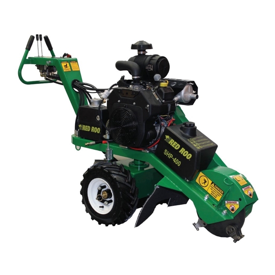
Name : Red Roo SHP400 Stump Grinder
Scan Code
GT622
GT622
SHP400
GARDEN
GARDEN
STumP
TILLER
TILLER
Grinder
GT5
GT622
GARDEN
TILLER
Commercial Environmental Equipment
GARDEN
Commercial Environmental Equipment
Online Demonstration Available at:
www.redroo.com/products/stumpgrinder
™
™
™
™
Advertisement
Table of Contents

Related Manuals for red roo SHP400


Summary of Contents for red roo SHP400
- Page 1 © Copyright 2001, Red Roo Sales & Service Company Pty. Ltd. 1301-0018 Adjust wheels and depth shoe accordingly while wheels from left to right in order to cover the entire structures, objects or people in front of the machine.
- Page 2 DRIVE and DIGGING CHAIN controls when depressed. operate the hydraulic trencher under the influence of © Copyright 2012, Red Roo Sales & Service Company Pty. Ltd. 1301-0069-A yourself and the people around you. foreign objects from the area.
Need help?
Do you have a question about the SHP400 and is the answer not in the manual?
Questions and answers