Advertisement
Table of Contents
- 1 Table of Contents
- 2 Foreword
- 3 Structure
- 4 How to Read the Service Manual
- 5 Conversion Table
- 6 Section 1 General
- 7 Group 1 Safety
- 8 Group 2 Specifications
- 9 Major Component
- 10 Specifications
- 11 Working Range
- 12 Weight
- 13 Lifting Capacities
- 14 Bucket Selection Guide
- 15 Undercarriage
- Download this manual
Advertisement
Table of Contents

Related Manuals for Hyundai Robex 260LC-9S


Summary of Contents for Hyundai Robex 260LC-9S
- Page 1 Robex 260LC-9S CRAWLER EXCAVATOR SERVICE MANUAL...
-
Page 2: Table Of Contents
TABLE OF CONTENT FOREWORD 1. Structure 2. How To Read The Service Manual 3. Conversion Table SECTION 1 GENERAL Group 1 Safety Group 2 Specifications 1. Major Component 2. Specifications 3. Working Range 4. Weight 5. Lifting Capacities 6. Bucket Selection Guide 7. - Page 3 2. Return Circuit 3. Drain Circuit Group 3 Pilot Circuit 1. Suction, Delivery And Return Circuit 2. Safety Solenoid Valve (safety Lever) 3. Boom Priority System 4. Travel Speed Control System 5. Main Relief Pressure Change Circuit 6. Arm Regeneration Cut System (cluster Type 1) 7.
- Page 4 2. Connection Table For Connectors SECTION 5 MECHATRONICS SYSTEM Group 1 Outline (cluster Type 1) Outline (cluster Type 2) Group 2 Mode Selection System (cluster Type 1) 1. Power Mode Selection System 2. Work Mode Selection System 3. User Mode Selection System Mode Selection System (cluster Type 2) 1.
- Page 5 1. Outline 2. Cluster 3. Cluster Connector Monitoring System (cluster Type 2) 1. Outline Monitoring System Consists Of The Monitor Part And Switch Part. The Monitor Part Gives Warnings When Any Abnormality Group 15 Fuel Warmer System 1. Specification 2. Operation 3.
- Page 6 2. Communication Error Flashes On The Cluster 3. Battery Charging Warning Lamp Lights Up(starting Switch : On) 4. When Coolant Overheat Warning Lamp Lights Up(engine Is Started) 5. When Air Cleaner Warning Lamp Lights Up(engine Is Started) 6. When Engine Oil Pressure Warning Lamp Lights Up(engine Is Started) 7.
- Page 7 2. Terminology 3. Operation For Performance Tests Group 2 Major Component 1. Main Pump 2. Main Control Valve 3. Swing Device 4. Travel Motor 5. Rcv Lever 6. Rcv Pedal 7. Turning Joint 8. Cylinder Group 3 Track And Work Equipment 1.
- Page 8 Group 8 Turning Joint 1. Removal And Install 2. Disassembly And Assembly Group 9 Boom, Arm And Bucket Cylinder 1. Removal And Install 2. Disassembly And Assembly Group 10 Undercarriage 1. Track Link 2. Carrier Roller 3. Track Roller 4. Idler And Recoil Spring Group 11 Work Equipment 1.
-
Page 9: Foreword
This section shows bolt specifications and standard torque values needed when mounting components to the machine. The specifications contained in this shop manual are subject to change at any time and without any advance notice. Contact your HYUNDAI distributor for the latest information. Find manuals at https://best-manuals.com... -
Page 10: How To Read The Service Manual
Revised edition mark(①②③…) Any additions, amendments or other changes will When a manual is revised, an edition mark is be sent to HYUNDAI distributors. recorded on the bottom outside corner of the Get the most up-to-date information before you pages. -
Page 11: Conversion Table
3. CONVERSION TABLE 3. CONVERSION TABLE Method of using the Conversion Table The Conversion Table in this section is provided to enable simple conversion of figures. For details of the method of using the Conversion Table, see the example given below. Example Example Method of using the Conversion Table to convert from millimeters to inches... - Page 12 Millimeters to inches Millimeters to inches 1mm = 0.03937in 0.039 0.079 0.118 0.157 0.197 0.236 0.276 0.315 0.354 0.394 0.433 0.472 0.512 0.551 0.591 0.630 0.669 0.709 0.748 0.787 0.827 0.866 0.906 0.945 0.984 1.024 1.063 1.102 1.142 1.181 1.220 1.260 1.299 1.339...
- Page 13 Liter to U.S. Gallon Liter to U.S. Gallon 1ℓ = 0.2642 U.S.Gal 0.264 0.528 0.793 1.057 1.321 1.585 1.849 2.113 2.378 2.642 2.906 3.170 3.434 3.698 3.963 4.227 4.491 4.755 5.019 5.283 5.548 5.812 6.6076 6.340 6.604 6.869 7.133 7.397 7.661 7.925 8.189...
- Page 14 kgf·m to to lbf lbf·ft ft 1kgf·m = 7.233lbf·ft 14.5 21.7 28.9 36.2 43.4 50.6 57.9 65.1 72.3 79.6 86.8 94.0 101.3 108.5 115.7 123.0 130.2 137.4 144.7 151.9 159.1 166.4 173.6 180.8 188.1 195.3 202.5 209.8 217.0 224.2 231.5 238.7 245.9 253.2...
- Page 15 kgf/cm kgf/cm to to lbf/in lbf/in 1kgf / cm = 14.2233lbf / in 14.2 28.4 42.7 56.9 71.1 85.3 99.6 113.8 128.0 142.2 156.5 170.7 184.9 199.1 213.4 227.6 241.8 256.0 270.2 284.5 298.7 312.9 327.1 341.4 355.6 369.8 384.0 398.3 412.5 426.7...
- Page 16 TEMPERATURE TEMPERATURE Fahrenheit-Centigrade Conversion. A simple way to convert a fahrenheit temperature reading into a centigrade temperature reading or vice verse is to enter the accompanying table in the center or boldface column of figures. These figures refer to the temperature in either Fahrenheit or Centigrade degrees. If it is desired to convert from Fahrenheit to Centigrade degrees, consider the center column as a table of Fahrenheit temperatures and read the corresponding Centigrade temperature in the column at the left.
-
Page 17: Section 1 General
SECTION 1 GENERAL SECTION 1 GENERAL Group 1 Safety Hints -------------------------------------------------------------------------------------------------------- 1-1 Group 2 Specifications ----------------------------------------------------------------------------------------------------- 1-10... -
Page 18: Group 1 Safety
SECTION 1 GENERAL SECTION 1 GENERAL GROUP 1 SAFETY GROUP 1 SAFETY FOLLOW SAFE PROCEDURE FOLLOW SAFE PROCEDURE Unsafe wor k practices are dangerous. Understand service procedure before doing work; Do not attempt shortcuts. WEAR PROTECTIVE CLOTHING WEAR PROTECTIVE CLOTHING Wear close fitting clothing and safety equipment appropriate to the job. - Page 19 PREPARE FOR EMERGENCIES PREPARE FOR EMERGENCIES Be prepared if a fire starts. Keep a first aid kit and fire extinguisher handy. Keep emergency numbers for doctors, ambulance ser vice, hospital, and fire department near your telephone. 13031GE04 PROTECT AGAINST FLYING DEBRIS PROTECT AGAINST FLYING DEBRIS Guard against injury from flying pieces of metal or debris;...
- Page 20 KEEP RIDERS OFF EXCAVATOR KEEP RIDERS OFF EXCAVATOR Only allow the operator on the excavator. Keep riders off. Riders on excavator are subject to injury such as being struck by foreign objects and being thrown off the excavator. Riders also obstruct the operator's view resulting in the excavator being operated in an unsafe manner.
- Page 21 SUPPORT MACHINE PROPERLY SUPPORT MACHINE PROPERLY Always lower the attachment or implement to the ground before you work on the machine. If you must wor k on a lifted machine or attachment, securely support the machine or attachment. Do not support the machine on cinder blocks, hollow tiles, or props that may crumble under 13031GE10 continuous load.
- Page 22 BEWARE OF EXHAUST FUMES BEWARE OF EXHAUST FUMES Prevent asphyxiation. Engine exhaust fumes can cause sickness or death. If you must operate in a building, be positive there is adequate ventilation. Either use an exhaust pipe extension to remove the exhaust fumes or open doors and windows to bring enough outside air into the area.
- Page 23 SERVICE MACHINE SAFELY SERVICE MACHINE SAFELY Tie long hair behind your head. Do not wear a necktie, scarf, loose clothing or necklace when you work near machine tools or moving parts. If these items were to get caught, severe injury could result.
- Page 24 AVOID HEATING NEAR PRESSURIZED AVOID HEATING NEAR PRESSURIZED FLUID LINES FLUID LINES Flammable spray can be generated by heating near pressurized fluid lines, resulting in severe burns to yourself and bystanders. Do not heat by welding, soldering, or using a torch near pressurized fluid lines or other flammable materials.
- Page 25 PREVENT ACID BURNS PREVENT ACID BURNS Sulfuric acid in battery electrolyte is poisonous. It is strong enough to burn skin, eat holes in clothing, and cause blindness if splashed into eyes. Avoid the hazard by: 1. Filling batteries in a well-ventilated area. 2.
- Page 26 DISPOSE OF FLUIDS PROPERLY DISPOSE OF FLUIDS PROPERLY Improperly disposing of fluids can harm the environment and ecology. Before draining any fluids, find out the proper way to dispose of waste from your local environmental agency. Use proper containers when draining fluids. Do not use food or beverage containers that may mislead someone into drinking from them.
-
Page 27: Group 2 Specifications
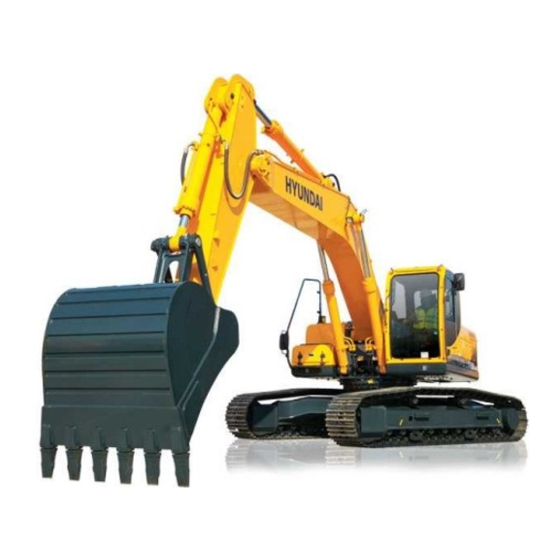
GROUP 2 SPECIFICATIONS GROUP 2 SPECIFICATIONS 1. MAJOR COMPONENT 1. MAJOR COMPONENT Battery box Fuel tank Hydraulic tank Main pump Engine Radiator Tooth Bucket Turning joint Swing motor Main control valve Oil cooler Arm cylinder Boom Boom cylinder Muffler Counterweight Bucket cylinder Connecting link Idler... -
Page 28: Specifications
2. SPECIFICATIONS 2. SPECIFICATIONS 1) 1) R260LC-9S R260LC-9S ·5.85 5.85 m m (19' 2") BOOM and 3.05 (19' 2") BOOM and 3.05 m m (10' 0") ARM (10' 0") ARM I(I') B(L) 2609S2SP02 Description Unit Specification Operating weight kg (lb) 25200 (55560) Bucket capacity (SAE heaped), standard 1.08 (1.41) - Page 29 2) 2) R260NLC-9S R260NLC-9S ·5.85 5.85 m m (19' 2") BOOM and 3.05 (19' 2") BOOM and 3.05 m m (10' 0") ARM (10' 0") ARM I(I') B(L) 2609S2SP04 Description Unit Specification 25100 (55300) Operating weight kg (lb) 1.08 (1.41) Bucket capacity (SAE heaped), standard 9920 (32' 7") Overall length...
- Page 30 3) 3) R260LC-9S HIGH WALKER R260LC-9S HIGH WALKER ·5.85 5.85 m m (19' 2") BOOM and 3.05 (19' 2") BOOM and 3.05 m m (10' 0") ARM (10' 0") ARM I(I') B(L) 2609S2SP05 Description Unit Specification Operating weight 27450 (60520) kg (lb) Bucket capacity (SAE heaped), standard 1.08 (1.41)
-
Page 31: Working Range
3. WORKING RANGE 3. WORKING RANGE R260LC-9S, R260NLC-9S [5.85 m (19' 2") BOOM] 1) 1) R260LC-9S, R260NLC-9S 2609S2SP03 Description 2.10m (6' 11") Arm 2.50m (8' 2") Arm 3.05m (10' 0") Arm 3.60m (11' 10") Arm Max digging reach 9550 mm (31' 4") 9870 mm (32' 5") - Page 32 R260LC-9S HIGH WALKER [5.85 m (19' 2") BOOM] 2) 2) R260LC-9S HIGH WALKER 2609S2SP09 Description 2.10m (6' 11") Arm 2.50m (8' 2") Arm 3.05m (10' 0") Arm 3.60m (11' 10") Arm Max digging reach 9550 mm (31' 4") 9870 mm (32' 5") 10360 mm (34' 0")
-
Page 33: Weight
4. WEIGHT 4. WEIGHT 1) 1) R260LC-9S, R260NLC-9S, R260LC-9S, R260NLC-9S, R260LC-9S R260NLC-9S Item ← ← Upperstructure assembly 10500 23150 ← ← Main frame weld assembly 2360 5200 ← ← Engine assembly 1170 ← ← Main pump assembly ← ← Main control valve assembly ←... - Page 34 R260LC-9S HIGH WALKER R260LC-9S HIGH WALKER R260LC-9S HIGH WALKER Item Upperstructure assembly 10500 23150 Main frame weld assembly 2360 5200 Engine assembly 1170 Main pump assembly Main control valve assembly Swing motor assembly Hydraulic oil tank assembly Fuel tank assembly Counterweight 4600 10140...
-
Page 35: Lifting Capacities
5. LIFTING CAPACITIES 5. LIFTING CAPACITIES R260LC-9S R260LC-9S 5.85 m (19' 2") boom, 3.05 m (10' 0") arm equipped with 1.08 m (SAE heaped) bucket and 600 mm (24") triple grouser shoe. Load radius At max. reach Load point 1.5 m (5 ft) 3.0 m (10 ft) 4.5 m (15 ft) 6.0 m ( 20ft) - Page 36 2) 2) R260NLC-9S R260NLC-9S 5.85 m (19' 2") boom, 3.05 m (10' 0") arm equipped with 1.08 m (SAE heaped) bucket and 600 mm (24") triple grouser shoe. Load radius At max. reach Load point 1.5 m (5 ft) 3.0 m (10 ft) 4.5 m (15 ft) 6.0 m ( 20ft) 7.5 m ( 25ft)
- Page 37 3) 3) R260LC-9S HIGH WALKER R260LC-9S HIGH WALKER 5.85 m (19' 2") boom, 3.05 m (10' 0") arm equipped with 1.08 m (SAE heaped) bucket and 600 mm (24") triple grouser shoe. Load radius At max. reach Load point 1.5 m (5 ft) 3.0 m (10 ft) 4.5 m (15 ft) 6.0 m ( 20ft)
-
Page 38: Bucket Selection Guide
6. BUCKET SELECTION GUIDE 6. BUCKET SELECTION GUIDE GENERAL BUCKET GENERAL BUCKET 0.60 m 1.27 m 1.08 m 1.03 m 0.79 m 1.50 m heaped bucket heaped bucket heaped bucket heaped bucket Recommendation Capacity Width 5.85m (19' 2") boom Weight 2.1m arm 2.5m arm 3.05m arm... - Page 39 2) 2) ROCK AND HEAVY DUTY BUCKET ROCK AND HEAVY DUTY BUCKET ◈1.07m ◈1.46m ⊙1.16m ◈1.27m ◈1.15m heaped bucket heaped bucket heaped bucket heaped bucket Recommendation Capacity Width 5.85 m (19' 2") boom Weight CECE Without With 2.1 m arm 2.5 m arm 3.05 m arm 3.6 m arm...
-
Page 40: Undercarriage
7. UNDERCARRIAGE 7. UNDERCARRIAGE 1) 1) TRACKS TRACKS X-leg type center frame is integrally welded with reinforced box-section track frames. The design includes dry tracks, lubricated rollers, idlers, sprockets, hydraulic track adjusters with shock absorb- ing springs and assembled track-type tractor shoes with triple grousers. 2) 2) TYPES OF SHOES TYPES OF SHOES... - Page 41 This as a preview PDF file from best-manuals.com Download full PDF manual at best-manuals.com...
Need help?
Do you have a question about the Robex 260LC-9S and is the answer not in the manual?
Questions and answers