Download Print this page

Advertisement

Quick Links

SECTION 00 - GENERAL
SECTION 10 - ENGINE
SECTION 18 - CLUTCH
SECTION 21 - TRANSMISSIONS
SECTION 23 - DRIVE LINES
SECTION 25 - FRONT AXLE MECHANICAL TRANSMISSION
SECTION 27 - REAR MECHANICAL TRANSMISSION
SECTION 31 - MECHANICAL POWER TAKE-OFF
SECTION 33 - BRAKING SYSTEM
SECTION 35 - HYDRAULIC SYSTEM
SECTION 41 - STEERING
SECTION 44 - AXLES AND WHEELS
SECTION 55 - ELECTRICAL SYSTEM
SECTION 90 - PLATFORM, CAB, BODYWORK
The following pages are the collation of the contents pages from each section and
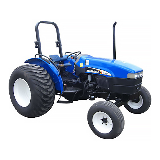
chapter of the TN55, TN65, TN70, TN75 Repair manual. Complete Repair part #
87034092.
The sections used through out all New Holland product Repair manuals may not be
used for each product. Each Repair manual will be made up of one or several books.
Each book will be labeled as to which sections are in the overall Repair manual and
which sections are in each book. The sections listed above are the sections utilized for
the TN55, TN65, TN70, TN75 Tractors.
2003 NEW HOLLAND NORTH AMERICA, INC.
Printed In U.S.A.
TN55, TN65, TN70, TN75
REPAIR MANUAL
COMPLETE CONTENTS
. . . . . . . . . . . . . . . . . . . . . . . . . . . . . . . . . . . . . . . . . . . .
. . . . . . . . . . . . . . . . . . . . . . . . . . . . . . . . . . . . . . . . . . . . . .
. . . . . . . . . . . . . . . . . . . . . . . . . . . . . . . . . . . . . . . . . . . . . .
. . . . . . . . . . . . . . . . . . . . . . . . . . . . . . . . . . . . . . . . . .
. . . . . . . . . . . . . . . . . . . . . . . . . . . . . . . . . . . . . . . . . . . .
. . . . . . . . . . . . . . . . . . . . . . . . . . . . . . . . . . . . .
. . . . . . . . . . . . . . . . . . .
. . . . . . . . . . . . . . . . . . . . . .
. . . . . . . . . . . . . . . . . . . . . . . . . . . . . . . . . . . .
. . . . . . . . . . . . . . . . . . . . . . . . . . . . . . . . . .
. . . . . . . . . . . . . . . . . . . . . . . . . . . . . . . . .
. . . . . . . . . . . . . . . . . . . . . . . . . . . . . . . . .
. . . . . . . . . . . . . . . . . . . . . . . .
2
2
3
3
5
. . . . . . . . . . .
6
6
7
8
8
10
11
11
15
87034098
5/03

Advertisement

loading

Summary of Contents for New Holland TN55

  • Page 1 ......The following pages are the collation of the contents pages from each section and chapter of the TN55, TN65, TN70, TN75 Repair manual. Complete Repair part # 87034092.
  • Page 2 SECTION 00 - GENERAL BOOK 1 - 87034093 Chapter 1 - - General Instructions CONTENTS Section Description Page 10 000 General Instructions ............SECTION 10 - - ENGINE BOOK 1 - 87034093 Chapter 1 - - Engine...
  • Page 3 SECTION 18 - - CLUTCH BOOK 1 - 87034093 Chapter 1 - - Clutch CONTENTS Section Description Page 18 000 General specifications ............Torque settings .
  • Page 4 SECTION 21 - - TRANSMISSIONS BOOK 2 - 87034094 Chapter 2 - - Power Shuttle Transmission (8 + 8 and 16 + 16 versions) CONTENTS Section Description Page 21 000 Main data ..............Torque values .
  • Page 5 SECTION 21 - - TRANSMISSIONS BOOK 2 - 87034094 Chapter 2 - - Power Shuttle Transmission (8 + 8 and 16 + 16 versions) (Continued) CONTENTS Section Description Page HC -- Transmission oil temperature sender ........HD -- Hi/Lo Synchronizer operation (not used in standard) .
  • Page 6 SECTION 25 - - FRONT AXLE MECHANICAL TRANSMISSION BOOK 3 - 87034095 Chapter 1 - - Front Axle Mechanical Transmission CONTENTS Section Description Page 25 000 Main Data ..............Torque Settings .
  • Page 7 SECTION 27 - - REAR MECHANICAL TRANSMISSION BOOK 3 - 87034095 Chapter 1 - - Rear Mechanical Wheel Drive (Continued) CONTENTS Section Description Page 27 106 16 Rear Transmission/Gearbox, Removal--Installation ....... . 27 110 10 Differential Lock Engagement Sleeve, Adjusting .
  • Page 8 SECTION 33 - - BRAKING SYSTEM BOOK 3 - 87034095 Chapter 1 - - Braking System CONTENTS Section Description Page 33 000 Main data ..............Torque settings .
  • Page 9 SECTION 35 - - HYDRAULIC SYSTEM BOOK 4 - 87034096 Chapter 2 - - Open Centre System Auxiliary Control Valves CONTENTS Operation Description Page 35 000 Main data -- Tools -- Torque settings ..........Cross-sectional views .
  • Page 10 SECTION 41 - - STEERING BOOK 4 - 87034096 Chapter 1 - - Steering CONTENTS Operation Description Page 41 000 Torque settings main data -- tools ..........Operation .
  • Page 11 SECTION 44 - - AXLES AND WHEELS BOOK 4 - 87034096 Chapter 1 - - Axles and Wheels CONTENTS Section Description Page 44 000 Main data ..............Cross--sectional views .
  • Page 12 SECTION 55 - - ELECTRICAL SYSTEM BOOK 5 - 87034097 Chapter 2 - - Starting System CONTENTS Section Description Page 55 000 Technical information ............Torque settings .
  • Page 13 SECTION 55 - - ELECTRICAL SYSTEM BOOK 5 - 87034097 Chapter 4 - - Battery CONTENTS Section Description Page 55 000 Technical information ............Description and operation .
  • Page 14 SECTION 55 - - ELECTRICAL SYSTEM BOOK 5 - 87034097 Chapter 6 - - Electrical Circuits (After S/N 1268128) CONTENTS Section Description Page 55 000 Electrical circuit components ........... . . Location of fuses and relays (mechanical shuttle and power shuttle versions) .
  • Page 15 SECTION 55 - - ELECTRICAL SYSTEM BOOK 5 - 87034097 Chapter 7 - - Electrical Components CONTENTS Section Description Page 55 418 10 Multi--function instrument panel, Removal--Installation ....... 55 440 08 Electronic Control Module (ECM), Replacement .
  • Page 17 GENERAL INSTRUCTIONS IMPORTANT NOTICE All maintenance and repair work described in this manual must be performed exclusively by NEW HOLLAND service technicians, in strict accordance with the instructions given and using any specific tools necessary. Anyone performing the operations described herein without strictly following the instructions is personally re- sponsible for any eventual injury or damage to property.
  • Page 18 SECTION 00 - - GENERAL - - CHAPTER 1 SPARE PARTS Only use original NEW HOLLAND spare parts bearing the logo shown below. Only original spare parts guarantee the same quality, duration and safety as they are the same parts that are assembled during production.
  • Page 19 SECTION 00 - - GENERAL - - CHAPTER 1 SAFETY REGULATIONS WARNING AND DANGER SYMBOL This warning symbol points out important messages concerning your safety. Carefully read the following safety regulations and observe advised precautions in order to avoid poten- tial hazards and safeguard your health and safety.
  • Page 20 SECTION 00 - - GENERAL - - CHAPTER 1 Only use specified towing points for towing the If operating outside the workshop, position the tractor. Connect parts carefully. Make sure that tractor on a flat surface and lock in position. If all pins and/or locks are secured in position be- working on a slope, lock the tractor in position.
  • Page 21 SECTION 00 - - GENERAL - - CHAPTER 1 START UP HYDRAULIC SYSTEMS A liquid leaking from a tiny hole may be almost Never run the engine in confined spaces that are invisible but, at the same time, be powerful not equipped with adequate ventilation for ex- enough to penetrate the skin.
  • Page 22 Front axle: axle case ....4.5 (1.19) TN55 lateral final drives wi- thout brakes (each) ..0.8 (0.21) TN55 lateral final drives with brakes (each) .
  • Page 23 SECTION 10 - - ENGINE - - CHAPTER 1 SECTION 10 - - ENGINE Chapter 1 - - Engine CONTENTS Section Description Page 10 000 General specifications ............Data .
  • Page 24 SECTION 10 - - ENGINE - - CHAPTER 1 GENERAL SPECIFICATIONS Engine type: Hp TN 55 -- type 8035.05B.529 ........See data page 6--7 Hp TN 65 -- type 8035.05R.539 .
  • Page 25 SECTION 10 - - ENGINE - - CHAPTER 1 (continued) GENERAL SPECIFICATIONS Lubrication ......... . . forced, with gear pump 1st 50 hr oil (Break-in Engine Oil) .
  • Page 26 SECTION 10 - - ENGINE - - CHAPTER 1 (continued) GENERAL SPECIFICATIONS Timing ..........overhead valves operated camshaft located in engine block through tappets, pushrods and rockers;...
  • Page 27 SECTION 10 - - ENGINE - - CHAPTER 1 FUEL SYSTEM DATA Turbocharger (model TN 70 and TN 75): GARRETT type ........T 25 Injection pump .
  • Page 28 SECTION 10 - - ENGINE - - CHAPTER 1 MODEL TN 55 - - CALIBRATION DATA FOR BOSCH INJECTION PUMP TYPE VE 3/11 F 1150 L 767 - - VE 3/11 F 1150 L 767- -1 ASSEMBLY DATA CALIBRATION TEST CONDITIONS Test bench conforming to ISO 4008/1 .../2 Pump timing on engine: delivery start 9 ±...
  • Page 29 SECTION 10 - - ENGINE - - CHAPTER 1 (continued) 11. DELIVERY PROGRESSION Delivery per 1000 shots: cm (gallons) 1280 0 to 3.0 (0 to 0.0008) 1220 27 to 33 (0.007 to 0.008) 1150 50.5 to 53.5 (0.013 to 0.014) 59.5 to 60.5 (0.0157 to 0.0159) 52.8 to 60.8 (0.0139 to 0.016) 12.
  • Page 30 SECTION 10 - - ENGINE - - CHAPTER 1 MODEL TN 65 - - CALIBRATION DATA FOR BOSCH INJECTION PUMP TYPE VE 3/11 F 1150 L 766 - - VE 3/11 F 1150 L 766- -1 ASSEMBLY DATA CALIBRATION TEST CONDITIONS Test bench conforming to ISO 4008/1 .../2 Pump timing on engine: delivery start 9 ±...
  • Page 31 SECTION 10 - - ENGINE - - CHAPTER 1 (continued) 11. DELIVERY PROGRESSION Delivery per 1000 shots: cm (gallons) 1270 0 to 3.0 (0 to 0.0008) 1200 43.5 to 54.5 (0.0114 to 0.0144) 64.1 to 69.1 (0.0169 to 0.01825) 1100 63.5 to 69.5 (0.0167 to 0.01836) 55.8 to 63.8 (0.0147 to 0.01685) 1150...
  • Page 32 SECTION 10 - - ENGINE - - CHAPTER 1 MODELS TN 70 - - CALIBRATION DATA FOR BOSCH INJECTION PUMP TYPE - - VE 4/11 F 1150 L 764- -2 ASSEMBLY DATA CALIBRATION TEST CONDITIONS Pump timing on engine: delivery start 6 ±...
  • Page 33 SECTION 10 - - ENGINE - - CHAPTER 1 (segue) 12. DELIVERY PROGRESSION LDA pressure kPa Delivery per 1000 shots: cm (gal.) 78,9 to 79,9 (0.0208 to 0.0211) 1270 0 to 3.0 (0 to 0.0008) 1200 53 to 54 (0.0140 to 0.0142) 1150 67,5 to 71,5 (0.0178 to 0.0188) 80,5 to 81,5 (0.0212 to 0.0215)
  • Page 34 SECTION 10 - - ENGINE - - CHAPTER 1 MODEL TN 75 - - CALIBRATION DATA FOR BOSCH INJECTION PUMP TYPE VE 3/11 F 1150 L 764 - - VE 3/11 F 1150 L 764- -1 ASSEMBLY DATA CALIBRATION TEST CONDITIONS Pump timing on engine: delivery start 6 ±...
  • Page 35 SECTION 10 - - ENGINE - - CHAPTER 1 (continued) 12. DELIVERY PROGRESSION LDA pressure Delivery per 1000 shots: cm (gal.) 1300 0 to 3.0 (0 to 0.0008) 1200 47.5 to 63.5 (0.01254to 0.0168) 88 to 93 (0.0232 to 0.0246) 42.5 82.8 to 90.8 (0.0219 to 0.0240) 78.2 to 83.2 (0.0207 to 0.0220)
  • Page 36 SECTION 10 - - ENGINE - - CHAPTER 1 FUEL SUPPLY PUMP DATA mm (inches) Eccentricity of drive shaft ....... . . 3 (0.1181) Diameter of drive shaft at bushings .
  • Page 37 SECTION 10 - - ENGINE - - CHAPTER 1 CRANKSHAFT AND BEARINGS DATA CRANKSHAFT AND BEARINGS DATA mm (inches) mm (inches) Crankshaft ..........balanced with integral counterweights Standard journal diameter .
  • Page 38 SECTION 10 - - ENGINE - - CHAPTER 1 (continued) mm (inches) mm (inches) CRANKSHAFT AND BEARINGS DATA CRANKSHAFT AND BEARINGS DATA Maximum permitted tolerance on run--out of flywheel mounting flange surface relative to the crankshaft centreline, measured with 1/100 mm scale dial gauge resting on front flange surface (A, page 63 ) at a diameter of 108 mm (4.25 in.) (total gauge reading) .
  • Page 39 SECTION 10 - - ENGINE - - CHAPTER 1 PISTON DATA PISTON DATA mm (inches) mm (inches) Pistons ..........Pistons .
  • Page 40 SECTION 10 - - ENGINE - - CHAPTER 1 VALVE TIMING GEAR DATA VALVE TIMING GEAR DATA mm (inches) mm (inches) Timing gear tooth backlash ....... . 0.160 (0.0063) Inside diameter of intermediate gear bushings (fitted and reamed) .
  • Page 41 This as a preview PDF file from best-manuals.com Download full PDF manual at best-manuals.com...

This manual is also suitable for:

Tn65Tn70Tn75