
Subscribe to Our Youtube Channel
Related Manuals for CEM DT-5302


Summary of Contents for CEM DT-5302
- Page 1 DIGITAL LOW RESISTANCE TESTER INSTRUCTION MANUAL Low Resistance Tester (1) (1) (1) (2) 400m...
-
Page 3: Safety Information
I. SAFETY INFORMATION NEVER apply voltage or current to the meter that exceeds the specified maximum: USE EXTREME CAUTION when working with high voltages. DO NOT measure voltage if the voltage on the "COM" input jack exceeds 1000V above earth ground. NEVER connect the meter leads across a voltage source while the function switch is in the current, resistance, or diode mode. -
Page 4: Operating Principle
Safety symbols: Caution refer to this manual before using the meter. Dangerous voltages. Meter is protected throughout by double insulation or reinforced insulation. When servicing, use only specified replacement parts. CE Comply with EN-61010-1 II.OPERATING PRINCIPLE Suppose we wished to measure the resistance of some component located a significant distance away from our ohmmeter. - Page 5 An ingenious method of measuring the subject resistance in a situation like this involves the use of both an ammeter and a voltmeter. We know from Ohm's Law that resistance is equal to voltage divided by current (R = E/I). Thus, we should be able to determine the resistance of the subject component if we measure the current going through it and the voltage dropped across it: Current is the same at all points in the circuit, because it is a series...
- Page 6 Auto Power Off To conserve battery life, the meter will automatically turn off after approx. 30 minutes of non-use. When this happens, the state of the meter is saved. In order to disable auto power off function, power on the meter when any of the push function , except for HOLD, is pressed down.The “APO”...
- Page 7 OHMS Range Resolution Accuracy 400Ω 0.1Ω ± (1.0% + 4d) 4KΩ 1Ω 40KΩ 10Ω ± (1.5% + 2d) 400KΩ 100Ω 4MΩ ± (2.5% + 3d) 40MΩ 10kΩ ± (3.5% + 5d) DC Current Rang Resolution Accuracy 400µA 0.1µA 4000µA 1µA ±...
- Page 8 DC Voltage Rang Resolution Accuracy 400mV 0.1 mV 1 mV ± (1%+5d) 0.01V 400V 0.1V 1000V ± (1.2%+5d) AC Voltage Rang Resolution Accuracy/50~60Hz Accuracy/400Hz 400mV 0.1 mV ± (1.2%+10d) ± (2.5%+10d) 1 mV ± (1.0%+10d) ± (1.2%+10d) 0.01V ± (1.0%+10d) ±...
-
Page 9: Parts And Controls
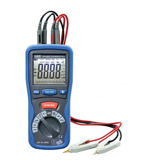
PARTS & CONTROLS Digital Display ① Data Hold Button ② MAX/MIN Button ③ Backlight Button ④ Mode/REL Button ⑤ Rotary Function switch ⑥ V Ω Cap mA E2 Jack ⑦ COM E1 jack ⑧ P2 Jack ⑨ P1 jack ⑩ PothooK ⑪... - Page 10 Button Function Operation HOLD button The HOLD function allows the meter to "freeze" a measurement for later reference. 1. Press the HOLD button to “freeze” the reading on the indicator. The “HOLD” message will be appear in the display. 2. Press the HOLD button again to return to normal operation. MAX/MIN button The MAX/MIN function allows the meter to capture the highest or lowest measurement for later reference.
-
Page 11: Dc/Ac Voltage Measurement
DC/AC VOLTAGE MEASUREMENT 1. Sert the black test lead into the negative COM jack and the red test lead into the V Ω Cap mA E2 Jack 2. Set the function switch to the V position. 3. Use the MODE button to select AC or DC Voltage 4. -
Page 12: Continuity Check
RESISTANCE [ Ω ] MEASUREMENT WARNING: To avoid electric shock, disconnect power to the unit under test and discharge all capacitors before taking any resistance measurements. Remove the batteries and unplug the line cords. 1. Set the function switch to the Ω position. 2. -
Page 13: Diode Test
DIODE TEST WARNING: To avoid electric shock, do not test any diode that has voltage on it. 1. Set the function switch to the position. 2. Insert the black test lead plug into the COM socket and the red test lead plug into the socket. - Page 14 Touch the test probe tips across the part under test. Read the capacitance value in the display. The display will indicate the proper decimal point and value. Note: For very large values of capacitance measurement time can be several minutes before the final reading stabilizes. The LCD displays DSC when discharging.
- Page 15 VI. Battery Replacement 1. When the low battery symbol appears on the LCD, the six 1.5V ‘AA’ batteries must be replaced. 2. Turn the meter off and remove the test leads. 3. Unsnap the tilt stand from the rear of the meter. 4.
- Page 16 V06/08...
Need help?
Do you have a question about the DT-5302 and is the answer not in the manual?
Questions and answers