Table of Contents
Advertisement
Quick Links
1 ANI-2F1
Module for process control in CO
1.1
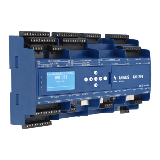
Front view
Fig. 1: Front view of ANI-2F1 with ANI-C control panel
1.2
Features
•
Standard rack controller with up to 2 compressors controlled by evaporation temperature
-
Compressor 1 constant (FC), compressors 2 directly controlled
-
FC compressor based on best COP
-
Monitoring of suction gas temperature
-
Oscillation protection function
-
Blocking time after compressor fault
-
3-step load shedding including Fastreturn
-
Operating hours counter for each compressor
•
High pressure and medium pressure control
•
Gas cooler fan control
•
Gas cooler monitoring
•
Refrigerant monitoring
•
CAN bus connection via patch cable and screw terminals
•
Fastening by top-hat rail
•
Connection to the Wurm system via Wurm CAN communication bus (C-BUS) and
FRIGODATA XP
Accessories
•
Control panel (ANI-C)
ANI-2F1_V1.0.4_PI_2020-06_EN
refrigeration plants with rack and gas cooler control
2
Subject to technical changes
FRIGOLINK
ANI-2F1
1
Advertisement
Table of Contents

Related Manuals for WURM ANI-2F1


Summary of Contents for WURM ANI-2F1
-
Page 1: Ani-2F1
Refrigerant monitoring • CAN bus connection via patch cable and screw terminals • Fastening by top-hat rail • Connection to the Wurm system via Wurm CAN communication bus (C-BUS) and FRIGODATA XP Accessories • Control panel (ANI-C) ANI-2F1_V1.0.4_PI_2020-06_EN Subject to technical changes... -
Page 2: Table Of Contents
ANI-2F1 ........ -
Page 3: Safety Instructions
Wurm GmbH & Co. KG Elektronische Systeme. Keep these instructions ready to hand for quick reference and pass them on with the device if the product is sold. - Page 4 Any versions not listed are special solutions for individual projects and are not described in detail in this document. This document automatically ceases to be valid if a new technical description is issued. Manufacturer: Wurm GmbH & Co. KG Elektronische Systeme, Morsbachtalstraße 30, D-42857 Remscheid You can find more information on our website at www.wurm.de.
-
Page 5: Circuit Diagram
81 82 83 84 81 82 83 84 201 202 203 204 205 206 207 208 209 210 202 203 205 206 207 208 209 210 98 99 98 99 Fig. 2: ANI-2F1 circuit diagram Power supply Terminal Power supply Potential Neutral 230V~... -
Page 6: Input Circuit Diagram
11 12 13 14 71 72 73 74 81 82 83 84 201 202 203 204 205 206 207 208 209 210 98 99 Fig. 3: ANI-2F1 input circuit diagram Digital inputs DI 1 - DI 20 Terminal Digital input Potential... -
Page 7: Analogue Inputs: Voltage Uin 1 - Uin 2
FRIGOLINK ANI-2F1 Terminal Digital input Potential Assignment DI 17 230V~ Fault HP rack DI 18 230V~ GC fan fault DI 19 230V~ Fault UPS / gas warn- ing 1 DI 20 230V~ Fault RCCB / gas warning 2 Analogue inputs: Voltage Uin 1 - Uin 2... -
Page 8: Output Circuit Diagram
81 82 83 84 201 202 203 204 205 206 207 208 209 210 202 203 205 206 207 208 209 210 98 99 Fig. 4: ANI-2F1 output circuit diagram Digital outputs: Relays K 1 - K 14 Contact arrange- Terminal Digital output... -
Page 9: Digital Outputs (Ssr) V 1 - V 4
FRIGOLINK ANI-2F1 Digital outputs (SSR) V 1 - V 4 Contact arrange- Terminal Digital output (SSR) Assignment ment 231/232 V 1 Not used 233/234 V 2 Not used Semiconductor V 3 Not available 4...60VA@230V~ Semiconductor V 4 Not available 4...60VA@230V~... -
Page 10: Communication Circuit Diagram
71 72 73 74 71 72 73 74 81 82 83 84 81 82 83 84 201 202 203 204 205 206 207 208 209 210 98 99 Fig. 5: ANI-2F1 communication circuit diagram Communication Terminal Potential Assignment C-BUS F-BUS RS 485 ANI-2F1_V1.0.4_PI_2020-06_EN... -
Page 11: Installing
4. (C) Swivel the bottom of the module towards the top-hat rail. 5. (D) Press the fastening safety catches (a) towards the module until they engage in the top-hat rail. Fig. 6: ANI-2F1 top-hat rail installation ANI-2F1_V1.0.4_PI_2020-06_EN Subject to technical changes... -
Page 12: Dismantling
FRIGOLINK ANI-2F1 Dismantling 1. Insert a flat-tip screwdriver in the openings in the fastening safety catches. 2. Pull the two fastening safety catches away from the housing until they are heard to click. 3. Swivel the bottom of the module gently away from the top-hat rail and towards yourself.
Need help?
Do you have a question about the ANI-2F1 and is the answer not in the manual?
Questions and answers