Advertisement
Quick Links
e m c t e s t e q u i p m e n t
M a n u a l
F o r
O p e r a t i o n
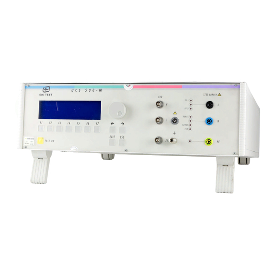
UCS 500Mx
The ultra-compact simulator
and its system modules
UCS 500 upgrade version
UCS 500 M4
UCS 500 M6
UCS 500 M6A
UCS500Mx - designed as a modular system - is the most
intelligent solution offering exactly what you need for full-
compliant immunity tests against transient and power fail
phenomena. The distinct operation features, convenient DUT
connection facilities, a clearly arranged menu structure and
display philosophy as well as the pre-programmed standard test
routines make testing easy, reliable and safe. Extendable by a
variety of test accessories the UCS500Mx is a universal
equipment for abroad range of recommendations even for three-
phase applications up to 100A
Version: 3.05 / 31.01.2005
Replaces: 3.04 / 17.12.2004
Filename:
UCS500Mx operating manual V305.doc
Printdate: 31.01.05
EN/IEC 61000-4-2
EN/IEC 61000-4-4
EN/IEC 61000-4-5
EN/IEC 61000-4-8
EN/IEC 61000-4-9
EN/IEC 61000-4-11
EN/IEC 61000-4-12
EN/IEC 61000-4-29
EN 61000-6-1
EN 61000-6-2
Advertisement


Need help?
Do you have a question about the UCS 500Mx and is the answer not in the manual?
Questions and answers