
Related Manuals for Elkron ELR60RT


Summary of Contents for Elkron ELR60RT
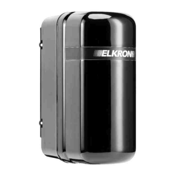
- Page 1 ELR60RT 2PH/60 Barriere radio da esterno doppio raggio - Portata 60 m Dual-beam outdoor radio barrier - Range 60 m DS80EL29-001A LBT81045...
-
Page 2: Table Of Contents
10. FREQUENCY SELECTION ............................... 29 11. WALK TEST AND INSTALLATION ..........................31 12. ALIGNING THE BARRIERS ............................. 32 13. ADJUSTING THE RESPONSE TIME ..........................35 14. SUPERVISION FUNCTION ............................... 35 15. TECHNICAL SPECIFICATIONS ............................36 16. F.A.Q....................................36 ELR60RT 2PH/60... -
Page 3: Avvertenze Generali
Elkron declina ogni responsabilità per guasti conseguenti ad errata installazione; mancata manutenzione, errato montaggio o uso. Elkron inoltre non è responsabile per errato o incompleto funzionamento del prodotto o mancata rilevazione di intrusione. AVVERTENZE PER L’INSTALLAZIONE ... -
Page 4: Descrizione Del Prodotto
La barriera trova il suo impiego ideale per protezioni perimetrali di aree interne ed esterne. Le principali caratteristiche sono: Regolazione del tempo di intervento Regolazione dell’angolo del fascio di protezione in senso orizzontale e verticale; Rilevazione tamper dell’apertura della barriera. VISTA DALL’ALTO 2° 60 m ALLARME ELR60RT 2PH/60... -
Page 5: Posizionamento Delle Barriere
3) NON posizionare le barriere a ridosso di strade: le luci dei fanali dirette sull’RX potrebbero creare disturbi 4) NON posizionare le barriere vicino a cancelli automatici: i segnali di fotocellule possono creare interferenze. ELR60RT 2PH/60... -
Page 6: Elenco Componenti Principali
Buzzer di allineamento (RX) Led ad alta intensità di allineamento (RX) Vite di regolazione verticale Lenti Unità base Porta batteria Batteria 3.6 V 20 Ah Molletta blocca batteria Guarnizione Piastra di fissaggio Coperchio IR Staffa a «U» per fissaggio a palo ELR60RT 2PH/60... -
Page 7: Modalità Di Installazione
Per non alterare le prestazioni e il grado di protezione (IP) della barriera è necessario fare attenzione a non deteriorare guarnizioni, plastiche e parti meccaniche del prodotto, utilizzando gli accessori originali. • Evitare di installare l’apparecchio ricevitore in una posizione in cui le ottiche possano essere irraggiate direttamente dal sole. ELR60RT 2PH/60... -
Page 8: Predisposizione Dei Dispositivi
Collegare la batteria ai contatti della barriera RX prestando attenzione alla polarità (CAVO NERO VERSO L’ESTERNO). Verificare l’accensione del LED rosso CAVO CAVO NERO ROSSO • Abilitare la funzione di apprendimento nell’unità di controllo (per ulteriori dettagli fare riferimento al suo manuale) ELR60RT 2PH/60... - Page 9 • Aprire ed alimentare anche la barriera TX collegando la batteria al connettore. • Per verificare l’allineamento e il funzionamento delle barriere, effettuare le operazioni descritte nei capitoli 11 e 12 del presente manuale, ELR60RT 2PH/60...
-
Page 10: Connessioni Trasmettitore
Posizionando tutti i DIP in OFF il trasmettitore sarà spento TMP1 CONNETTORE TAMPER Ingresso TAMPER aggiuntivo. Se non è previsto, DEVE essere chiuso AGGIUNTIVO da jumper. TAMPER a molla per l’anti rimozione del coperchio LED DI SEGNALAZIONE Lampeggia al collegamento dell’alimentazione CONFIGURAZIONE ALIMENTAZIONE: non necessaria ELR60RT 2PH/60... -
Page 11: Connessioni Ricevitore
TMP1 TAMPER Ingresso TAMPER aggiuntivo. Se non è previsto, DEVE essere chiuso da jumper. AGGIUNTIVO REGOLAZIONE TEMPO D’INTERVENTO TAMPER a molla per l’anti rimozione del coperchio LED DI Lampeggia al collegamento dell’alimentazione SEGNALAZIONE CONFIGURAZIONE ALIMENTAZIONE: ponticello su 3 V ELR60RT 2PH/60... -
Page 12: Selezione Della Frequenza
Posizionare in ON il DIP 6 e il DIP del canale desiderato sulla scheda RX. 1 2 3 4 5 6 Posizionare in ON il DIP del canale sulla scheda TX corrispondente. 1 2 3 4 1 2 3 4 5 6 ELR60RT 2PH/60... - Page 13 A taratura effettuata stringere la vite di regolazione orizzontale e uscire dalla funzione test posizionando in OFF il DIP 6 sulla scheda RX. WALK-TEST: per i successivi 60 secondi ogni evento di allarme verrà evidenziato da una segnalazione ottica e acustica. ELR60RT 2PH/60...
-
Page 14: Walk Test E Installazione
A seguito della taratura e della verifica del corretto il foro posto sotto l’ottica e procedere con funzionamento (vedi capitolo seguente), riposizionare l’allineamento il coperchio e fissarlo con la vite di chiusura posta sul lato inferiore del dispositivo. ELR60RT 2PH/60... -
Page 15: Allineamento Delle Barriere
2) Collocare il filtro davanti all’ottica TX, posizionando i due ganci sui perni della forcella dell’ottica, per perfezionare la ricerca del segnale di allineamento in caso di condizioni critiche. È sufficiente l’applicazione del filtro solo sul TX, non occorre ripetere l’operazione anche sull’RX. ELR60RT 2PH/60... - Page 16 N.B. Il suono fisso del buzzer ha una durata massima di 3 minuti. Per ottenere un buon allineamento è necessario compiere una rotazione COMPLETA sull’asse orizzontale dell’ottica RICEVITORE, effettuando così lo SCANNING del segnale ottico. ELR60RT 2PH/60...
- Page 17 N.B. per avere la certezza assoluta che l’allineamento delle ottiche sia reale (e quindi non vi siano falsi allineamenti dovuti a fotocellule di cancelli), coprite l’ottica con la mano: se il beep è continuo, vuol dire che il raggio vede un’altra fonte di infrarosso. ELR60RT 2PH/60...
-
Page 18: Regolazione Del Tempo Di Intervento
In funzionamento normale la barriera trasmette all’unità di controllo un segnale di supervisione ad intervalli da 30 a 50 minuti. Se l’unità di controllo non riceve il segnale dalla barriera entro un tempo prefissato, l’unità di controllo genererà un allarme di supervisione. ELR60RT 2PH/60... -
Page 19: Caratteristiche Tecniche
Il fabbricante, URMET S.p.A., dichiara che il tipo di apparecchiatura radio: BARRIERE RADIO DA ESTERNO DOPPIO RAGGIO PORTATA 60m ELR60RT 2PH/60 sono conformi alla direttiva 2014/53/UE. Il testo completo della dichiarazione di conformità UE è disponibile al seguente indirizzo Internet: www.elkron.com. -
Page 20: General Precautions
Elkron accepts no liability for failures due to incorrect installation, lack of maintenance or improper assembly or use. In addition, Elkron is not liable for incorrect or incomplete functioning of the product or its failure to detect intrusion. -
Page 21: Product Description
The ideal use of the barrier is for perimeter protection of indoor and outdoor areas. The main features include: Adjustment of response time; Vertical and horizontal adjustment of the protection beam angle; Tamper detection when the barrier is opened. VIEW FROM ABOVE 2° 60 m ALARM ELR60RT 2PH/60... -
Page 22: Positioning The Barriers
3) DO NOT place the barriers along the side of roads: headlights pointing towards the RX could create disturbances 4) DO NOT place the barriers close to automatic gates: signals from the photocells may create interference. ELR60RT 2PH/60... -
Page 23: List Of Main Components
4. LIST OF MAIN COMPONENTS Tamper Horizontal adjustment screw Alignment buzzer (RX) High-intensity alignment LED (RX) Vertical adjustment screw Lenses Base unit Battery compartment 3.6 V 20 Ah battery Battery lock clip Gasket Fixing plate IR cover U-shaped bracket for pole mounting ELR60RT 2PH/60... -
Page 24: Installation Procedure
Necessary precautions must be taken in order not to alter the barrier’s performance and (IP) protection rating. Take care not to damage the gaskets, plastic and mechanical parts of the product, and use original accessories. • Avoid installing the receiver in a position where the sun’s rays can directly affect the optics. ELR60RT 2PH/60... -
Page 25: Preparing The Devices
Connect the battery to the contacts on the RX barrier, paying attention to the polarity (BLACK CABLE TOWARDS THE OUTSIDE). Check that the red LED lights up. BLACK WIRE WIRE • Enable the learning feature in the control unit (for more details, see the control unit manual). ELR60RT 2PH/60... - Page 26 • Open the TX barrier and power it by connecting the battery to the connector. • To check the alignment and functioning of the barriers, perform the operations described in sections 11 and 12 of this manual. ELR60RT 2PH/60...
-
Page 27: Transmitter Connections
TMP1 ADDITIONAL TAMPER Additional TAMPER input. If not required, it MUST be closed by a CONNECTOR jumper. Spring-loaded TAMPER to prevent removal of the cover. SIGNAL LED Flashes when the power supply is connected. POWER SUPPLY CONFIGURATION: not necessary ELR60RT 2PH/60... -
Page 28: Receiver Connections
Additional TAMPER input. If not required, it MUST be closed by a jumper. TAMPER ADJUSTING RESPONSE TIME Spring-loaded TAMPER to prevent removal of the cover. Flashes when the power supply is connected . SIGNAL LED POWER SUPPLY CONFIGURATION: jumper on 3 V ELR60RT 2PH/60... -
Page 29: Frequency Selection
Set DIP 6 and the DIP of the desired channel on the RX circuit board to the ON position. 1 2 3 4 5 6 Set the DIP of the channel on the corresponding TX circuit board to ON. 1 2 3 4 1 2 3 4 5 6 ELR60RT 2PH/60... - Page 30 Once calibration is complete, tighten the horizontal adjustment screw and exit the test function by setting DIP 6 to off on the RX circuit board. WALK-TEST: for the next 60 seconds, each alarm event will be highlighted by an optical and acoustic signal. ELR60RT 2PH/60...
-
Page 31: Walk Test And Installation
Fix the device to the rear plate using the hole located After calibration and verification of correct operation under the optics and proceed with the alignment; (see following section), replace the cover and secure it with the closing screw located on the lower part of the device. ELR60RT 2PH/60... -
Page 32: Aligning The Barriers
2) Place the filter in front of the TX optics, positioning the two hooks on the optics fork pins, to fine-tune the search for the alignment signal in the case of critical conditions. It is sufficient to use the filter on the TX only, with no need to repeat the operation on the RX. ELR60RT 2PH/60... - Page 33 RECEIVER optics must perform a FULL rotation on the horizontal axis to SCAN the optical signal. • Once calibration is complete, tighten the horizontal adjustment screw and exit test mode by resetting DIP 6 to OFF on the RX circuit board. Two beeps will indicate the end of the TEST function. ELR60RT 2PH/60...
- Page 34 Note. For absolute certainty that the optics are truly aligned (with no false alignments caused by gate photocells), cover the optics with your hand: a continuous beep indicates that the beam detects another infrared source. ELR60RT 2PH/60...
-
Page 35: Adjusting The Response Time
In normal operation, the barrier sends a supervisory signal to the control unit at intervals from 30 to 50 minutes. If the control unit does not receive the signal from the barrier within a predetermined time, the control unit will generate a supervisory alarm. ELR60RT 2PH/60... -
Page 36: Technical Specifications
Hereby, URMET S.p.A. declares that the radio equipment type: DUAL-BEAM OUTDOOR RADIO BARRIER - RANGE 60m ELR60RT 2PH/60 is in compliance with Directive 2014/53/EU. The full text of the EU declaration of conformity is available at the following internet address: www.elkron.com.
Need help?
Do you have a question about the ELR60RT and is the answer not in the manual?
Questions and answers