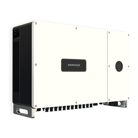
Sunways STT Series Quick Installation Manual
Grid-connected pv inverter three phase dual mppt
Hide thumbs
Also See for STT Series:
- User manual (32 pages) ,
- Quick installation manual (2 pages) ,
- User manual (27 pages)
Table of Contents
Advertisement
Quick Links
0 1
Packing List
Inverter×1
Wall Bracket×1
Expansion Bolt×5
3Pin Terminal×1
Monitoring
AC Terminal×1
Ground Terminal×1
6Pin
Device × 1 (Optional)
Figure 1 Packing list
Export limit & control version 2pcs ; RS485 and DRED version 1pcs (This
①
connector is already pre-installed inside the inverter).
Note
②
STT 4-12kW 2pcs / STT 15kW 3pcs / STT 17-25kW 4pcs.
③
DRED version only (This connector is already pre-installed inside the inverter).
Installation Spacing
0 2
500mm
300mm
300mm
500mm
Figure 2 Installation spacing
Figure 3 Front view
Bracket Dimensions
0 3
Use the wall bracket as the template to mark the position of 5 holes on the wall.
Use an electrical driller with 10mm diameter bit to drill 5 holes on the wall and
make sure hole depth is 80mm.
300mm
150mm
150mm
10mm
10mm
150mm
Figure 4 Dimensions of wall bracket
Figure 5 Mark the holes on the wall
Mounting the Inverter
0 4
Insert the expansion tubes into the holes and tighten them, then fix the bracket
onto the wall with expansion screws by using a cross screwdriver. Lift up the
inverter with both hands, hang the back rail on the fixed wall bracket carefully.
Figure 6 Fix the wall bracket
Figure 7 Mounting the inverter
DC Connector Assembly Procedure
0 5
Use a 2.5-4mm² PV cable, strip off the cable sheath for 7mm, insert the stripped
head into the metal terminal and use a crimping plier to press it tight, insert the
metal terminal into the corresponding PV connector and tighten the nut.
①
②
2.5-4.0mm²
PV Terminal×2
Figure 8 Strip off the cable sheath
Quick
Guide
User
Manual
Inspection
Report
User Manual×1
Quick Guide×1
③
Terminal×1
Inspection Report×1
Figure 10 Tighten the DC connector
DC Connector Connection
0 6
550mm
Figure 11 DC connector connection
Insert the positive and negative
connectors into the inverter PV
Logo
connectors respectively.
Note:1. Disconnect the AC breaker on the grid
side when connecting the PV connectors.
Display
2. The DC switch must be switched to "OFF position".
AC Connector Assembly
0 8
Peel the insulation sleeve of AC cable
off for 50mm, and peel off the end of
3L /PE / N wires for 8mm.
Wire
Diameter: 13-18mm
Figure 13 Recommended AC cable info
AC Connector Connection
0 9
An AC breaker must be connected on the AC side of the inverter. The
recommended AC cable and breaker for Sunways STT 4-25kW series three-phase
inverters are shown in the following table:
Connect the AC connector to the inverter AC terminal, and rotate the AC
connector buckle clockwise until it' s tight enough.
Model
STT-4KTL
STT-5KTL
STT-6KTL
STT-8KTL
STT-10KTL
STT-12KTL
STT-15KTL
STT-17KTL
STT-20KTL
STT-25KTL
Note: Check the local standards for more details.
Grid Connection Steps
1 0
1. Check whether all connectors are correctly connected.
2. Switch the AC breaker on.
3. Turn the DC Switch to "ON" position.
4. The inverter starts self-checking and the screen displays "checking" .
5. After self-checking is completed, the inverter will start to generate power.
The power indicator will be light up and the real-time power will be
displayed on the screen.
+
Length:7mm
_
Figure 9 Press the metal terminal
Ground Terminal Connection
0 7
Figure 12 Ground terminal connection
Note:Inverter must be well-grounded for resisting
surge voltage shock and improving EMI
performance.
Insert the stripped end of 3L/N/PE
cables into the AC terminal head.
Tighten the screws in the terminal
with an Allen-key to ensure a reliable
connection.
Allen-key
8mm
50mm
Figure 14 AC connector assembly
Copper wire
Breaker
2.5-10mm²
20A
2.5-10mm²
20A
2.5-10mm²
20A
3.2-10mm²
20A
4-10mm²
32A
6-10mm²
32A
6-10mm²
32A
8-10mm²
40A
8-10mm²
40A
Figure 15 AC connector connection
8-10mm²
50A
QUICK INSTALLATION GUIDE
STT 4~25kW Series
Grid-connected PV Inverter
Three Phase Dual MPPT
Sunways Technologies Co.,Ltd.
S11-00013-01
Advertisement
Table of Contents

Summary of Contents for Sunways STT Series
- Page 1 300mm AC Connector Connection QUICK INSTALLATION GUIDE 0 9 An AC breaker must be connected on the AC side of the inverter. The recommended AC cable and breaker for Sunways STT 4-25kW series three-phase 150mm 150mm 10mm 10mm inverters are shown in the following table:...
- Page 2 “admin” and click “Sign in” . Restart +61 2 8188 2450 Figure 25 Figure 26 Sunways Technologies Co.,Ltd. Sunways AU Support: 9. After the reboot, the green indicator on the WiFi module will be always on. Phone: +61 2 8188 2450 Website: www.suntech-power.com.au Figure 18 Email: services@suntech-power.com.au...


Need help?
Do you have a question about the STT Series and is the answer not in the manual?
Questions and answers