
Related Manuals for Enatel RW312U


Summary of Contents for Enatel RW312U
- Page 1 Enatel DC System Manual Installation and Operation Manual Model: RW312U, RW324U, RW348U RW512U, RW517U, RW624U, RW748U Series Rectifiers Version 3.6...
- Page 2 Warranty Enatel provides a one year limited warranty, details as stated under the manual section Appendix I Enatel Energy Standard Limited Warranty Policy on page 22. System Compliance Low Voltage Directive (LVD) 2014/35/EU Electromagnetic Compatibility Directive (EMC) 2014/30/EU Copyright © Enatel 2020 All rights reserved.
-
Page 3: Table Of Contents
Rectifiers in Parallel ....................... 15 Commissioning the Rectifier ......................16 Servicing ............................... 16 Warnings ............................16 Troubleshooting ........................17 Fuses .............................. 17 Setting Changes ..........................18 Default Settings ........................20 Enatel DC System Manual Page 3 of 26 Model: RWxxx Version: 3.6... - Page 4 Adjust Temperature Compensation Slope ..............22 Adjusting the alarm output volt low/high setting ............22 Appendix I Enatel Energy Standard Limited Warranty Policy ........... 22 Warranty Exclusions and Restrictions ................23 Battery Warranty ........................23 Initiating a Warranty Claim ....................23 Disclaimer ...........................
-
Page 5: Safety
Nominal Rated Voltage Maximum Power Model Input Volts Current Voltage Voltage Range Current Rating RW312U 110 – 240V 13.7V 11.5-15V 300W RW324U 110 – 240V 27.4V 22-30V 300W RW348U 110 – 240V 54.0V 45-60V 300W RW512U 110 – 240V 8.5A 13.7V... -
Page 6: Leds
Boost Charge mode and in Current Limit, the Boost Timer is inhibited. When the rectifier comes out of Current Limit, the Boost Timer starts and will automatically switch Page 6 of 26 Enatel DC System Manual Model: RWxxx Version: 3.6... -
Page 7: Low Voltage Disconnect And Reset (Optional)
Temperature Compensation Batteries require different charging voltages depending on the ambient temperature of the battery. The colder the battery, the higher the voltage required to charge the battery. Page 7 of 26 Enatel DC System Manual Model: RWxxx Version: 3.6... -
Page 8: Current Limit
The rectifiers should have the load share signal connected between the rectifiers. This is achieved by connecting the load share signal line on the Alarm & Control Page 8 of 26 Enatel DC System Manual Model: RWxxx Version: 3.6... -
Page 9: 2.13 External Shutdown
Mains failure • Rectifier failure • Rectifier Off Normal (over temperature, over voltage, current limit) • High voltage output • Low voltage output • Page 9 of 26 Enatel DC System Manual Model: RWxxx Version: 3.6... -
Page 10: Installation
It must be on a vertical surface (wall), perpendicular to the floor. It must be mounted in a “landscape” orientation with side connectors on the right. Do not mount rectifiers above each other. Observe all instructions on the rectifier. Page 10 of 26 Enatel DC System Manual Model: RWxxx Version: 3.6... -
Page 11: Figure 1: Rectifier Mounting
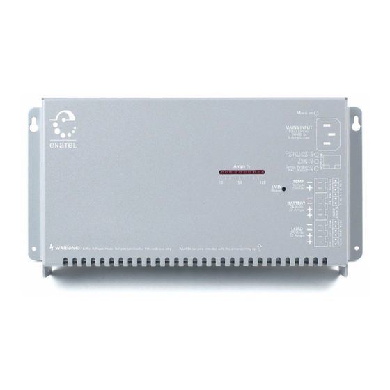
The rectifier should be mounted 50mm clear of any other solid object, and care should be taken to ensure that air entering the rectifier is cool air and has not been heated by other equipment. Figure 2: Rectifier View Page 11 of 26 Enatel DC System Manual Model: RWxxx Version: 3.6... -
Page 12: Cabling
1.5mm2 wire should be used from the rectifier, connecting to a longer length of large cross section wire. Connectors supplied for the rectifier are 4W Page 12 of 26 Enatel DC System Manual Model: RWxxx Version: 3.6... -
Page 13: Temperature Compensation
For load and alarm sharing, an alarm and control interface cable should be connected to each parallel rectifier to ensure that all rectifiers load share automatically. When two or Page 13 of 26 Enatel DC System Manual Model: RWxxx Version: 3.6... -
Page 14: Internal Alarm Card (Optional)
The relays are Single Pole Double Throw (or changeover). Both Normally Closed (NC) and Normally Open (NO) contacts are provided. Contact rating is 100v DC, 1A max and all Page 14 of 26 Enatel DC System Manual Model: RWxxx Version: 3.6... -
Page 15: Rectifier Fail/Mains Fail
This means that you only need to connect one alarm card to the alarm circuitry when the rectifiers are connected in parallel. Page 15 of 26 Enatel DC System Manual Model: RWxxx Version: 3.6... -
Page 16: Commissioning The Rectifier
To isolate the rectifier from the mains, simply unplug the IEC mains connector from the rectifier DANGER Do not operate the rectifier if the covers are damaged or removed in any way. Page 16 of 26 Enatel DC System Manual Model: RWxxx Version: 3.6... -
Page 17: Troubleshooting
Although there are fuses inside the rectifier, these are rated such that their failure indicates a fault requiring qualified service. Do not attempt to repair these fuses. However, for IEC 60950 the fuse ratings are required to be specified. Page 17 of 26 Enatel DC System Manual Model: RWxxx Version: 3.6... -
Page 18: Setting Changes
The rectifier must be disconnected from the battery and load. : The trimpots to adjust the settings are accessible on the rear side of the rectifier. Refer to Figure 8: Trimpot Functions for the trimpot descriptions. Page 18 of 26 Enatel DC System Manual Model: RWxxx Version: 3.6... -
Page 19: Figure 7: Trimpot Access
Figure 7: Trimpot Access Trimpot Access (on product REAR) See Figure 8: Trimpot Functions Figure 8: Trimpot Functions Enatel DC System Manual Page 19 of 26 Model: RWxxx Version: 3.6... -
Page 20: Default Settings
Disconnect the Temperature Compensation Probe. Connect an accurate current meter in series with the load. Turn the mains on to the rectifier, wait 10 seconds and then adjust Page 20 of 26 Enatel DC System Manual Model: RWxxx Version: 3.6... -
Page 21: Adjust Current Limit
First, adjust the LVD Voltage trimpot to set the required ‘on’ voltage limit. Then adjust the LVD Hysterisis trimpot to set the required ‘off’ voltage limit. Page 21 of 26 Enatel DC System Manual Model: RWxxx Version: 3.6... -
Page 22: Adjust Temperature Compensation Slope
Enatel’s factory; or (b) in the case of resale by an authorized Enatel reseller, whichever is the lesser of i) the date on the sales invoice or ii) ninety (90) days after original shipment by Enatel factory. -
Page 23: Warranty Exclusions And Restrictions
Enatel’s warranty policy; the account has breached or is in dispute of Enatel’s commercial terms and conditions. Note Enatel warranty does not cover data loss, regular back-ups to separate storage is required. -
Page 24: Disclaimer
In no case shall Enatel’s liability under this warranty exceed the value of the unit provided. If the law prohibits Enatel from disclaiming implied warranties or warranties of merchantability, all such warranties are limited to the greatest extent permitted by law. - Page 25 This page is intentionally left blank. Page 25 of 26 Enatel DC System Manual Model: RWxxx Version: 3.6...
- Page 26 Enatel 66 Treffers Road Christchurch 8042 New Zealand...
Need help?
Do you have a question about the RW312U and is the answer not in the manual?
Questions and answers