Table of Contents
Advertisement
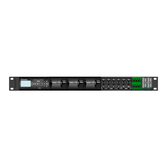
1U MICRO Compact System
Enatel DC System Manual
PSX24042x1F-x00 &
PSX24051xF-x00
Installation Manual
V2.1
Manufactured by Enatel Ltd.
321 Tuam Street
PO Box 22-333
Christchurch
New Zealand
Phone +64-3-366-4550
Fax +64-3-366-0884
Email
sales@enatel.net
www.enatel.net
Copyright © Enatel Ltd. 2010
Page 1 of 31
Advertisement
Table of Contents

Subscribe to Our Youtube Channel
Related Manuals for Enatel PSX24051 Series


Summary of Contents for Enatel PSX24051 Series
- Page 1 1U MICRO Compact System PSX24042x1F-x00 & PSX24051xF-x00 Installation Manual V2.1 Manufactured by Enatel Ltd. 321 Tuam Street PO Box 22-333 Christchurch New Zealand Phone +64-3-366-4550 Fax +64-3-366-0884 Email sales@enatel.net www.enatel.net Copyright © Enatel Ltd. 2010 Enatel DC System Manual Page 1 of 31...
-
Page 2: Table Of Contents
11.0 Appendix 2 - System Wiring Diagrams ................24 Appendix 3 - AC Input Transient Protection ................28 Appendix 4 - Model Specifications .................... 30 11.1 System Part Numbers - 3 Rectifier ................30 11.2 System Naming Convention ..................31 Enatel DC System Manual Page 2 of 31... - Page 3 Handle the equipment with care. Do not drop or lean on front panel or connectors. Keep away from moisture. Identification Labels Model numbers are clearly marked on all equipment. Please refer to these numbers in all correspondence with Enatel. Enatel DC System Manual Page 3 of 31...
-
Page 4: Scope
COPE This manual covers essential information for the installation and commissioning of the 1U MICRO Compact Enatel Compact DC Power System Range (see Appendix for individual model specifications). System set-up for the rectifiers, alarms etc., are provided in separate manuals for the SM35/6 supervisory module and RM848 rectifier. -
Page 5: System Overview
DC earthing section of this manual. The earth link can be completely removed from the system to isolate earths. Please see the DC earthing section of the manual. Enatel DC System Manual Page 5 of 31... -
Page 6: Installation
Fig 2, Fitting of ETSI rack mount tabs Note: Fitment of tabs in some positions will require the temporary removable of the DC Battery connectors and SM3x monitor. These can be replaced once fitment is complete. Enatel DC System Manual Page 6 of 31... -
Page 7: Ac Cabling
The fuse used in the RM848 is a slow-blow 10A fuse. The tripping curve for this is shown in Appendix 2 at the rear of this manual. Enatel DC System Manual Page 7 of 31... - Page 8 Therefore, they can never be overloaded. As a result, the wire can never be over-loaded by the rectifier – it can only see fault current. As a result, depending on local authorities, only fault current protection may be catered for by the upstream protective device. Enatel DC System Manual Page 8 of 31...
-
Page 9: Dc Cabling
Note: Systems with only one battery breaker specified can be fitted with an additional load breaker. Connection to the output from this breaker is made through the remaining SB50 power-pole. Connector layout for PSX24042x1F-x00 Connector layout for PSX24051x1F-x00 Fig 6, DC Connector detail Enatel DC System Manual Page 9 of 31... -
Page 10: Alarm/Ancillary Cabling
(float) voltage accordingly. As a result, it is not necessary to have the temperature sensor touching the batteries. If the Battery Temperature Sensor is removed a “battery temp fault” alarm is generated. Enatel DC System Manual Page 10 of 31... - Page 11 For remote communications and direct computer connection to the Compact System, refer to the monitor manual. These connections can be made via the mini-USB port on the front panel of the monitor (computer connection), and the Ethernet port (SM36 web-based communications only). Enatel DC System Manual Page 11 of 31...
-
Page 12: Alarm Mapping To Volts-Free Relays
Relay 3: Summary Urgent alarm Relay 4: User Configurable Relay 5: User Configurable Relay 6: User Configurable As mentioned, if these mappings are not appropriate, they can be changed in the field to suit customer requirements. Enatel DC System Manual Page 12 of 31... -
Page 13: Circuit Breaker Fail Monitoring
This is because when a battery breaker is tripped, there may be very little voltage difference across the breaker, making electronic fail detection problematic. Hence, if no battery is connected, the breaker must be “on” to clear the Battery Breaker Fail alarm. Enatel DC System Manual Page 13 of 31... -
Page 14: Lvd Operation
SM3x will loose voltage sense (as voltage sense is measuring rectifier bus voltage) but still maintains operation for monitoring system. The LVD contactor will not re- engage until the rectifier power is restored (i.e., until the DC bus voltage is restored). Enatel DC System Manual Page 14 of 31... -
Page 15: Dc Earthing
DC output from AC earth. This modification should be made with both -/+ earth PCB’s in the +ve earth position (or with the fixed positive earth system) Fig 11, isolated earth option Enatel DC System Manual Page 15 of 31... -
Page 16: Commissioning
2-3V below float to float voltage. At this point the batteries will be drawing some current to bring them to a full state of charge. Load Start-up 1. Ensure downstream load connections have been made and there are no loose/floating cables. Enatel DC System Manual Page 16 of 31... - Page 17 This will prevent anyone leaving the batteries only powering the load (in which case the batteries would go flat). Enatel DC System Manual Page 17 of 31...
-
Page 18: Dc System Commissioning Check-List
(using a aerosol can of freeze, or a tub of ice) the temperature sensors. Battery Temperature High (urgent) __________° C Battery Temperature Low (non-urgent) __________° C Room Temperature High (non-urgent) __________° C Enatel DC System Manual Page 18 of 31... - Page 19 - Status Log Sampling Interval to 7 days (provides a “snapshot” of the battery state every 7 days) - Discharge Log Sampling Interval to 1 minute - Discharge Log Continuation Time to 5 minutes (this is the length of time Enatel DC System Manual Page 19 of 31...
- Page 20 Therefore, to check a Battery MCB Fail alarm, simply open one of the battery MCB’s. If batteries are connected to the system at this time, the alarm may take a few moments to activate. Once test is complete, turn breaker back on. Battery MCB Fail (urgent) Enatel DC System Manual Page 20 of 31...
- Page 21 This will prevent anyone leaving the batteries only powering the load (in which case the batteries would go flat). Enatel DC System Manual Page 21 of 31...
-
Page 22: Maintenance
AINTENANCE As ENATEL Power Systems are state of the art electronic systems, very little routine maintenance is required System • Check all load and battery & alarm cable connections are tight. Monitor • The monitor can give a good indication of the condition of the system. Alarm logs can show issues with the system and rectifiers and should be regularly checked. -
Page 23: Appendix 1 - Rectifier Input Fuse Curves
10.0 1 - R PPENDIX ECTIFIER NPUT URVES RM848 Input Fuse Enatel DC System Manual Page 23 of 31... -
Page 24: Appendix 2 - System Wiring Diagrams
11.0 2 - S PPENDIX YSTEM IRING IAGRAMS 1U MICRO Compact system, PSX24042xF-000 Enatel DC System Manual Page 24 of 31... - Page 25 1U MICRO Compact system, PSX24042xF-200 Enatel DC System Manual Page 25 of 31...
- Page 26 1U MICRO Compact system, PSX24051xF-000 Enatel DC System Manual Page 26 of 31...
- Page 27 1U MICRO Compact system, PSX24051xF-200 Enatel DC System Manual Page 27 of 31...
-
Page 28: Appendix 3 - Ac Input Transient Protection
Some of the Enatel Power System models are provided with Type 2 Surge Protection Devices (SPDs) (as defined by IEC 61643-11). These devices are rated for repeated strikes of 20kA (8/20µs waveform as shown above), and single shot protection of 40kA. - Page 29 Notes on AC cable installation and SPDs The following precautions must be adhered to when installing AC cabling. 1. Avoid running input and output cables from AC Surge Protection Devices together: 2. Avoid “Tee’d” Connections: Enatel DC System Manual Page 29 of 31...
-
Page 30: Appendix 4 - Model Specifications
1U MICRO Compact System ±ve SM35 PSX2405121F-000 1U MICRO Compact System SM36 PSX2405121F-200 1U MICRO Compact System ±ve SM36 *Note: Part numbers specify the maximum number of Battery MCB’s that can be fitted. Enatel DC System Manual Page 30 of 31... -
Page 31: System Naming Convention
Cable Access F - Front Access Specific Model Number -000 - Standard System (positive earth) -200 - Universal Earth System (negative earth as default) PSX 24 04 2 1 1 F -000 Enatel DC System Manual Page 31 of 31...
Need help?
Do you have a question about the PSX24051 Series and is the answer not in the manual?
Questions and answers