Advertisement
Quick Links
Replacing the Billboard PC Controller
(PN 1109502601SP)
The PC controller transmits and converts signals between control cabinet components and
the billboard. The PC controller's removable 40GB hard drive stores operating programs
such as Windows XP and a web–based content management software.
Before you begin
Kit contents
Part Number
1109210101
1181220001
Key
Power cord
Mounting rails
1109610108
Tools / Safety equipment needed
Full body safety harness with lanyard
#2 Phillips head screw driver
M
21, 2008
AY
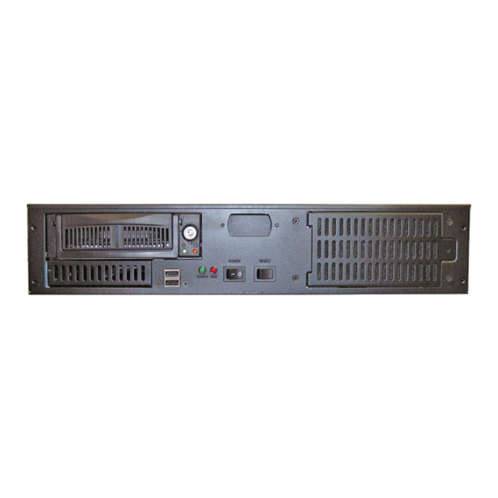
Figure 1. Front view of PC controller.
Qty
1
PC controller relays messages to and from the billboard.
40GB removable hard drive stores billboard operating software and program files.
1
Note: Software programs are pre–installed at the factory.
Hard drive key is used to lock the hard drive into place in the PC controller or
unlock the hard drive for removal.
1
Note: The PC controller will not function if the hard drive is not locked into place.
1
The power cord connects to the UPS and supplies power to the PC controller.
2
Side mounting rail assemblies, used for rack mounting the PC controller.
1
Instructions
Adaptive Micro Systems • 7840 North 86th Street • Milwaukee, WI 53224 USA • 414-357-2020 • 414-357-2029 (fax) • http://www.adaptivedisplays.com
Adaptive is a registered trademark of Adaptive Micro Systems. MEDIAMaster is a trademark of Adaptive Micro Systems.
Description
© Copyright 2008 Adaptive Micro Systems LLC. All rights reserved.
All other brand and product names are trademarks or registered trademarks of their respective companies.
PN 1109610108
. A
REV
Advertisement

Related Manuals for Adaptive 1109502601SP


Summary of Contents for Adaptive 1109502601SP
- Page 1 © Copyright 2008 Adaptive Micro Systems LLC. All rights reserved. Adaptive Micro Systems • 7840 North 86th Street • Milwaukee, WI 53224 USA • 414-357-2020 • 414-357-2029 (fax) • http://www.adaptivedisplays.com Adaptive is a registered trademark of Adaptive Micro Systems. MEDIAMaster is a trademark of Adaptive Micro Systems.
- Page 2 PC C EPLACING THE ILLBOARD ONTROLLER Replacing the PC controller WARNING! Possible fall hazard. When servicing billboard components, service personnel must use a full body safety harness with lanyard. Connect the lanyard to the billboard head’s safety cables; otherwise serious injury or death may occur. ➩...
- Page 3 PC C EPLACING THE ILLBOARD ONTROLLER 4. Disconnect the PC controller’s power and communication cables. • Unplug the PC controller’s power cord from the UPS. • Remove all other cables plugged into the back of the PC controller. 5. Remove the PC controller from the control cabinet. A.
- Page 4 PC C EPLACING THE ILLBOARD ONTROLLER 7. Connect all cables associated with the PC controller. PC controller rear view UPS receptacles Item Port Component connection PC #1 power cord label ID #17 plugs into UPS load 1’s top receptacle. Power PC #2 power cord label ID #22 plugs into UPS load 2’s top receptacle.
- Page 5 PC C EPLACING THE ILLBOARD ONTROLLER Updating the player.ini file To communicate with the billboard, the IP address in the player.ini file on the PC controller must match the billboard’s IP address. ➩ To update the player.ini file 1. Using the KVM drawer, access the replacement PC controller’s desktop, see Figure 2 on page 2 for more details.
- Page 6 PC C EPLACING THE ILLBOARD ONTROLLER Verifying USB to RS485 COM port Billboard light sensors, temperature readings, and other RS485 signals critical to the operation of the billboard will not be received by the PC controller, and eventually affecting billboard operation. 1.
- Page 7 PC C EPLACING THE ILLBOARD ONTROLLER 3. Click the Hardware tab and select Device Manager. Click the Hardware tab. Click the Device Manager. The Device Manager window may open out of the viewing area on the KVM monitor. Figure 11. System properties window. 4.
- Page 8 PC C EPLACING THE ILLBOARD ONTROLLER 6. Click the Port Settings tab and select Advanced. Click Port Settings tab. Click Advanced. Figure 14. USB serial port properties window. 7. Open the COM Port Number’s drop down menu and select COM4, even if it is in use. Click OK Select COM4, even if it is in use.
Need help?
Do you have a question about the 1109502601SP and is the answer not in the manual?
Questions and answers