Table of Contents
Advertisement
Advertisement
Table of Contents

Related Manuals for NUCLEONIX SYSTEMS GA720

Summary of Contents for NUCLEONIX SYSTEMS GA720
- Page 1 I N S T R U C T I O N M A N U A L GAMMA AREA MONITOR TYPE : GA720 NUCLEONIX SYSTEMS PRIVATE LIMITED Plot No : 162 A & B, PHASE II, I.D.A.Cherlapally, Hyderabad - 500 051 Ph: 91-040-27263701/30918055, FAX : 27262146, e-mail : info@nucleonix.net...
-
Page 2: Table Of Contents
Contents S.No. Description Page No. Unpacking CHAPTER I Introduction 01-01 CHAPTER II Front panel and Side panel controls / 02-02 indications / diagrams CHAPTER III Specifications 03-03 CHAPTER IV Installation 04-04 CHAPTER V Operating Instructions 05-09 CHAPTER VI Side panel Connector Details 10-10 CHAPTER VI I Calibration... -
Page 3: Unpacking
UNPACKING The Gamma Area Monitor Type: GA720 has been thoroughly tested and is dispatched in ready to operate condition. However, on unpacking and prior to operation, it is advisable to check visually and make sure that there is no visible damage caused in transit. -
Page 4: Chapter I Introduction
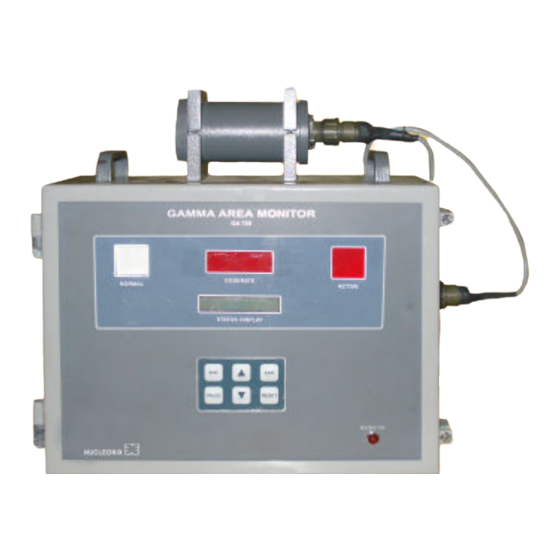
CHAPTER- I INTRODUCTION Gamma Area monitor (Micro) Type: GA 720, manufactured & supplied by NUCLEONIX SYSTEMS is designed using state-of-art electronic devices (latest) including microcontroller with embedded code. Use of these devices makes it compact & highly reliable. Powerful embedded code adds-up and enhances its performances and gives extra advantage from the angle of fault diagnostics. - Page 5 CHAPTER - II FRONT PANEL & SIDE PANEL CONTROLS FRONT PANEL CONTROLS 2.1.1. NORMAL & ACTIVE LAMPS The NORMAL lamp (GREEN) glows during acquisition mode until the dose rate exceeds alarm preset value. Once dose rate exceeds alarm preset value then the NORMAL lamp turns OFF and the ACTIVE lamp (RED) blinks.
-
Page 6: Chapter Iii Specifications
CHAPTER - III SPECIFICATIONS Radiation detected X – ray & Gamma Radiation Range 0.1 mR/hr to 100 mR/hr Detector Halogen quenched GM tube LND712 Accuracy +/-10% Full scale Auto – ranging direct reading, 6 digit 7 segment LED display & 16x2 LCD display. Display 6 x 7 segment display is interfaced using multiplexed display driver IC &... -
Page 7: Chapter Iv Installation
CHAPTER - IV INSTALLATION This unit can be used as wall mounted unit or can be operated as a table top model. For wall mounting arrangement the unit is provided with suitable clamps to be fixed on to wall and hooks have been provided on the unit for hanging. -
Page 8: Operating Instructions
CHAPTER – V OPERATING INSTRUCTIONS 5.1. INTRODUCTION: This chapter illustrates details on configuring and operating the instrument, for a desired installation in a plant environment. Basically, operating instructions are illustrated with the help of menu options / responses that appear on LCD / LED displays. Each of the menus facilitate the user to choose function/ value to be set or entered as desired for its operation, at the installed location. - Page 9 & facilitates the user to enter ‘ALARM SET POINT’. ALARM SET POINT GA720 will show the current default alarm set value of 5.00 mR/hr. If user wants he can change to another value, by or keys.
- Page 10 IP ADDRESS XXX.XXX.XXX.XXX BAUD RATE Baud rate is to be selected for data communication in a networked environment for RS485 communication. There are two options as indicated in LCD display. BAUD RATE 9600/19200 One can select any of the two options for baud rate by using by or keys. Having done that, user can go to next option by pressing ‘PROG’...
- Page 11 5.11 DEVICE ADDRESS This is a three character numerical value. This is RS485 address of the instrument limits 0 - 255 Default settings is = 000 DEVICE ADDRESS User can select desired three digit address (ID) of the instrument. Use or keys to load this value.
- Page 12 Engineering Unit Max. scale (4-20mA) Min. scale (4-20mA) mR/hr 100.00 000.00 Sv/hr 1000.0 0000.0 2000 0000 50000 00000 Followed by this, on pressing ‘PRG’ button, the following menu appears ‘load default settings? Note : Max. & Min. scales are primarily for current loop scaling, for control room operation. Also, in the visual LED display also the same scales are set.
-
Page 13: Side Panel Connector Details
CHAPTER - VI SIDE PANEL CONNECTOR DETAILS 3 pin MS Male connector (Mains) 3 pin MS (panel mount connector) Pin Number Signal Live Neutral Chasis/Earth/GND 17 pin MS Male connector (EXT I/O) Pin Number Signal 17 pin MS (panel mount connector) A,B,C,D,E,F No Connection COM Changeover II... - Page 14 This unit namely Gamma Area Monitor Type GA 720 has been calibrated at Radiation Standard & Calibration Lab of Nucleonix Systems (P) Ltd., using Gamma Survey Instruments Calibrator of AEA Technology, USA. It operates in the range of Dose rate mode (0.1 mR/hr – 100mR/hr) for Gamma Radiation.
-
Page 15: Availing Of Maintenance/ Calibration Services And
For their nearest local address & phone no's look into their websites. Transit insurance if the customer feels is necessary it is to be covered. Nucleonix Systems will not receive the equipments sent by other modes of transportation, such as Rail/Road. - Page 16 & customs clearance charges in both the countries. Nucleonix systems plans to introduce audio visuals on web or on CDs to facilitate product demonstration, installation & minor maintenance very soon.
- Page 17 Foreign customers can calibrate Nucleonix make Radiation monitors/equipments in their country at any of their accredited Radiation calibration labs. Nucleonix systems will be happy to provide any help and guidance if needed, for calibration. Alternatively if you send the equipment here to India we can also provide calibration services.
- Page 18 Obsolescence in electrons is quite rapid. If you enter into AMC guaranteed service for the period of AMC will be the responsibility of Nucleonix Systems. Nucleonix Systems will maintain Engineers at your disposal to attend to AMC calls on time Without AMC prompt service calls are not guaranteed.
-
Page 19: Block Diagram Description
CHAPTER - IX BLOCK DIAGRAM DESCRIPTION Area gamma monitor GA720 is shown in block diagram on the next page. It mainly consists of two parts. Detector probe with associated electronics & Main measuring unit with majority of µC based functional electronics & embedded code. - Page 20 > > > < < < > < < >...
-
Page 21: Factory Acceptance Test / Qa Report / Calibration Data
AREA GAMMA MONITOR MODEL NO. GA720 Sl. No. Date NUCLEONIX SYSTEMS PRIVATE LIMITED Plot No: 162 A & B, Phase II, I.D.A. Cherlapally, Hyderabad - 500 051. Ph: 91-040-27263701, Fax: 27262146, e-mail: info@nucleonix.com Document Name : FAT Procedures for GA720... - Page 22 QC REPORT FOR GAMMA AREA MONITOR TYPE: GA720 Sl.No : Date: 1. MECHANICAL INSPECTION (HARDWARE FIXTURES): Description Observation Hardware fixtures Check the dimensions of the unit OK/NOT OK Front panel control Check the keypad, displays & lamp stickers properly OK/NOT OK...
- Page 23 3. FUNCTIONAL TESTING: Description Observation Status at the time of switch The unit should go to acquisition mode on OK/NOT OK ‘Switch ON’ and & is displayed in both x segment and LCD display respectively. Testing of front panel key Check the front panel keys for about 20 times OK/NOT OK each.
- Page 24 SOURCE CALIBRATION & CORRESPONDING VOLTAGE, CURRENT LOOP VALUES : Expected Observed Dose rate Dose rate 1 mR/hr 5 mR/hr 10 mR/hr 20 mR/hr 50 mR/hr 1800 100 mR/hr Passed Status Over Load Test 10 Times Highest Range 100 Times Highest Range 4.MECHANICAL INSPECTION (HARDWARE FIXTURES) Description Observation...
- Page 25 AREA GAMMA MONITOR (TYPE: GA720) CALIBRATION DATA Name of the Customer : Work Order No Unit Sl.No. Calibration Date Calibration Factor Calibrated by Name of the calibration device used : Cesium Cs-137, 137mCi Standard Calibration Device (NIST traceable). (source certificate & calibration certificate of the device is...
Need help?
Do you have a question about the GA720 and is the answer not in the manual?
Questions and answers