
Subscribe to Our Youtube Channel
Related Manuals for Lars Thrane Iridium Certus LT-4100


Summary of Contents for Lars Thrane Iridium Certus LT-4100
- Page 1 User & Installation Manual LT-4100 Satellite Communications System Iridium Certus® 100 Document Number: 95-102576 Rev. 1.00 Release date: October 29, 2021 Copyright © Lars Thrane A/S Denmark ALL RIGHTS RESERVED...
- Page 3 Manuals issued by Lars Thrane A/S are periodically revised and updated. Anyone relying on this information should acquire the most current version e.g. from Lars Thrane A/S. Lars Thrane A/S is not responsible for the content or accuracy of any translations or reproductions, in whole or in part, of this manual from any other source.
- Page 4 Failure to comply with these precautions or with specific warnings elsewhere in this manual violates safety standards of design, manufacture and intended use of the equipment. Lars Thrane A/S assumes no liability for the customer's failure to comply with these requirements. Instructions for the Operator...
- Page 5 - Consult the dealer or an experienced radio/TV technician for help. This product does not contain any user-serviceable parts. Repairs should only be made by an authorized Lars Thrane A/S service center. Unauthorized repairs or modifications could result in permanent damage to the equipment and void your warranty and your authority to operate this device under Part 15 regulations.
- Page 6 All safety instructions and guidelines in this manual must be observed. The safety instructions are listed in the beginning of the manual. The guidelines are to be found in the separate chapters, where it is needed. Lars Thrane A/S www.thrane.eu...
- Page 7 1.00R Table 1: Software Versions IMPORTANT: The latest software released by Lars Thrane A/S must always be used for new installations of the LT-4100 System and should be updated to ensure the best possible performance of the system and services.
- Page 8 LT-4100 User & Installation Manual Rev 1.00 Introduction Record of Revisions Rev. Description Release Date Initials 1.00 Original document. October, 2021 Lars Thrane A/S www.thrane.eu...
-
Page 9: Table Of Contents
Activating the System ............................. 45 Acquire a Certus SIM Card .......................... 45 Pre- and Postpaid Voice Features ......................45 Who’s My Service Provider ........................46 Change of Hardware and Software ........................ 47 Change of Hardware ........................... 47 Lars Thrane A/S www.thrane.eu... - Page 10 App. C Multiple talkers and multiple listeners ..................112 App. D GNSS sentences ..........................113 App. E BAM Sentences ..........................114 App. F GNSS Receiver Integrity States ..................... 115 App. G - Specifications ..........................120 Lars Thrane A/S www.thrane.eu viii...
- Page 11 App. L - Outline Drawing: Pole Mount (1.5” pipe, 38.8mm), Antenna Unit ........... 126 App. M - Outline Drawing: Pole Mount (2.0” pipe, 53.0mm), Antenna Unit ......... 127 App. N - Outline Drawing: LT-3120 Handset .................... 128 App. O - Outline Drawing: LT-3121 Cradle ....................129 Lars Thrane A/S www.thrane.eu...
-
Page 12: Introduction
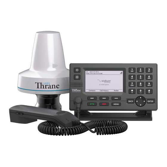
The LT-4100 system can be used as the primary satellite communication product on vessels, covering the basic communication needs in terms of connectivity between the ship and shore and ship to ship. Lars Thrane A/S www.thrane.eu Page 1 of 129... -
Page 13: Application And Limitations
The LT-4100 system shall be installed according to manufacturer’s User & Installation Manual. • The LT-4100 system includes an integrated Global Navigation Satellite System (GNSS) receiver for position fixing. • The LT-4130 Antenna Unit operational low temperature is: -40°C (-40°F) Lars Thrane A/S www.thrane.eu Page 2 of 129... -
Page 14: Unpacking (In-The-Box)
To avoid electric shock, do not apply power to the LT-4100 system components if there is any sign of shipping damage to any part of a unit or the outer cover. Read the Safety Instructions at the front of this manual before installing or operating the system. Lars Thrane A/S www.thrane.eu Page 3 of 129... -
Page 15: Accessories
N connector. NOTE: For further details on the cable and connectors, please contact Lars Thrane A/S. A coaxial cable up to a length of 500 meters can be used for connecting the LT-4110 Control Unit and the LT-4130 Antenna Unit. Details about the coaxial cable, specification, and cable lengths, are described in LT-4130 Antenna Unit on page 11. -
Page 16: System Overview
Iridium® satellite constellation. The LT-4100 system is working on the Iridium® NEXT satellites. An overview of the LT-4100 system is illustrated in Figure 1. Figure 1: LT-4100 system - basic components and interfaces. The LT-4100 system consists of the following units, provided by Lars Thrane A/S: • LT-4110 Control Unit •... -
Page 17: Installation And Mounting
SIM card, marked ‘SIM’ • 5-pin connector (female) for LT-3120 Handset (front of the control unit) The interfaces on the back side of the LT-4110 Control Unit are illustrated in Figure 3 on page 7. Lars Thrane A/S www.thrane.eu Page 6 of 129... - Page 18 Mount the unit on a rigid structure with a minimum of exposure to vibration and shock • Mount the unit in an area with an ambient temperature between -15°C to +55°C (+5°F to +131°F) Lars Thrane A/S www.thrane.eu Page 7 of 129...
- Page 19 Installation and Mounting The Bracket Mount and Flush Mount for the LT-4110 Control Unit are illustrated in Figure 4 and Figure 5. Figure 4: Bracket Mount, Control Unit. Figure 5: Flush Mount, Control Unit. Lars Thrane A/S www.thrane.eu Page 8 of 129...
-
Page 20: Lt-3120 Handset
LT-4110 Control Unit. A BAM alert will be activated (Lost handset). NOTE: The LT-3120 Handset must be operated together with the LT-3121 Cradle, for the off-hook detection circuit to work. The LT-3121 Cradle is described in LT-3121 Cradle on page 10. Lars Thrane A/S www.thrane.eu Page 9 of 129... -
Page 21: Lt-3121 Cradle
1.4 m (4.6 ft). An outline drawing for the LT-3121 Cradle is available in App. O - Outline Drawing: LT-3121 Cradle on page 129. Lars Thrane A/S www.thrane.eu Page 10 of 129... -
Page 22: Lt-4130 Antenna Unit
Mount the unit on a rigid structure with a minimum of exposure to vibration and shock • Mount the unit using either the Bracket Mount or Pole Mount provided by Lars Thrane A/S • Mount the unit outdoor with an ambient temperature between -40°C to +55°C (-40°F to +131°F) •... - Page 23 Maximum allowed torque is 2 Nm when connecting the coaxial cable N-connector (male) to the N-connector (female) of the LT-4130 Antenna Unit. No tooling must be used for fastening the coaxial cable thread nut as illustrated in Figure 11 above. Lars Thrane A/S www.thrane.eu Page 12 of 129...
- Page 24 Due to the adjacency of the Iridium and Inmarsat frequency bands, the LT-4130 Antenna Unit may not co-operate in the proximity of an active Inmarsat antenna unit, see Coexisting with Inmarsat L-band on page 18. Lars Thrane A/S www.thrane.eu Page 13 of 129...
- Page 25 LT-4130 Antenna Unit may be reduced, with no impact on the antenna performance. The performance of the LT-4130 Antenna Unit should be validated when the LT-4100 system is installed. Lars Thrane A/S www.thrane.eu Page 14 of 129...
- Page 26 15 times the diameter of the obstruction is kept. Figure 15: LT-4130 Antenna Unit – (separation distance to minor obstructions) The LT-4130 Antenna Unit must be mounted using one of the mounts listed in Mounts on page 4 Lars Thrane A/S www.thrane.eu Page 15 of 129...
- Page 27 (port and starboard directions), where no obstructions block the Iridium satellite signal, to maintain full functionality under extreme roll conditions. Also, the upper hemisphere should be without any blockages to the Iridium satellites. Lars Thrane A/S www.thrane.eu Page 16 of 129...
- Page 28 Iridium satellites as illustrated in Figure 16 and in Figure 17 (clear view angle below the horizontal plan). To have the best possible performance obstructions should be below the marked lines of these two illustrative figures. Lars Thrane A/S www.thrane.eu Page 17 of 129...
- Page 29 Mount the LT-4130 Antenna Unit at a minimum distance of 1 m from an Inmarsat C antenna. Mount the LT-4130 Antenna Unit at a minimum distance of 3 m from an Inmarsat Fleet Broadband antenna. Lars Thrane A/S www.thrane.eu Page 18 of 129...
-
Page 30: Pole Mount (1.5" Pipe, Ø38.8Mm), Antenna Unit
Remember to fasten the antenna lock pinot screw (1.2 Nm) after the pole mount and antenna unit have been screwed together. The Pole Mount (1.5” pipe), Antenna Unit interfaces to a pipe of maximum 1.5” (38.8 mm), measured outer diameter. Lars Thrane A/S www.thrane.eu Page 19 of 129... - Page 31 (antenna and pole lock) torques are specified in Figure 19 and Figure 20. The pole mount is made of milled aluminum (anodized). The pinot screws are made of A4 stainless steel. Lars Thrane A/S www.thrane.eu Page 20 of 129...
-
Page 32: Pole Mount (2.0" Pipe, Ø53.0Mm), Antenna Unit
Remember to fasten the antenna lock pinot screw (1.2 Nm) after the pole mount and antenna unit have been screwed together. NOTE: The Pole Mount (2.0” pipe, Ø53.0mm), Antenna Unit interfaces to a pipe of maximum 2.0” (53.0 mm), measured outer diameter. Lars Thrane A/S www.thrane.eu Page 21 of 129... - Page 33 (antenna and pole lock) torques are specified in Figure 22 and Figure 23. The pole mount is made of milled aluminum (anodized). The pinot screws are made of A4 stainless steel. Lars Thrane A/S www.thrane.eu Page 22 of 129...
-
Page 34: Interfaces
LT-4100 system is provided by connecting the proprietary 91-102118 Power Cable, 3m - delivered by Lars Thrane A/S. The power connector is mounted on the back side of the LT-4110 Control Unit and marked ‘PWR’, see Figure 24. - Page 35 LT-4100 User & Installation Manual Rev 1.00 Interfaces Chassis ground (GNDC) The chassis ground connector is placed on the back side of the LT-4110 Control Unit and marked with ‘GNDC’, see Figure 24 on page 23. Lars Thrane A/S www.thrane.eu Page 24 of 129...
- Page 36 Mini-SIM out. The full-sized card carrier contains the MSISDN number, while the SIM card itself contains the ICCID. Figure 25: Certus SIM card Lars Thrane A/S www.thrane.eu Page 25 of 129...
- Page 37 Area Network (LAN) with a DHCP server (e.g. a router). If connecting the LT-4110 Control Unit directly to a PC, the two will automatically negotiate an IPv4 Link-Local address. The current IP address can be found in the user interface display (Menu -> System -> Network: IP Address). Lars Thrane A/S www.thrane.eu Page 26 of 129...
- Page 38 Figure 27: AUX cable pin out NOTE: Use only the 91-100768 Auxiliary Cable, 3m delivered by Lars Thrane A/S for connecting to the AUX connector on the backside of the LT-4110 Control Unit. The Auxiliary Cable, 3m is an accessory part and must be acquired separately.
- Page 39 Figure 28: RS-422 Circuit Diagram for the LT-4110 CU Interface Drive Capability as a Talker and Listener • A(Rx+), B(Rx-), Y(Tx-): -60V to +60V • Short circuit protected • Galvanic isolated up to 1500V Lars Thrane A/S www.thrane.eu Page 28 of 129...
- Page 40 • GNSS (see GNSS sentences on page 81) • BAM (see BAM sentences page 82) The RS-422 interface can be configured using the web server, see GNSS and BAM on page 100. Lars Thrane A/S www.thrane.eu Page 29 of 129...
- Page 41 Connector interface is providing data communication and power to the antenna unit over a coaxial cable. The N connector marked with ‘ANT’ is illustrated on Figure 3 on page 7. NOTE: Do not connect or disconnect the antenna cable when the LT-4110 Control Unit is powered. Lars Thrane A/S www.thrane.eu Page 30 of 129...
- Page 42 The LT-4110 Control Unit has built in Bluetooth 4.0 with integrated antenna providing wireless communication between Bluetooth capable devices and the LT-4100 system. Max Power: RF Tx Power 10 dBm NOTE: The Bluetooth interface and pairing is described in Bluetooth on page 59. Lars Thrane A/S www.thrane.eu Page 31 of 129...
-
Page 43: Lt-4130 Antenna Unit
Lars Thrane A/S has calculated the maximum allowed cable lengths with two coaxial cables as illustrated in Table 6. The two coaxial cables are FF195LSFROH (~RG-58) and FF400LSFROH (~RG-214/LMR400). - Page 44 FF400LSFROH), then verify that the RF and DC coaxial cable requirements (Table 4 and Table 5) are respected and calculate the maximum cable length as a function of the input voltage and the total DC resistance. Contact Lars Thrane A/S to get assistance on selection and acceptance of a specific coaxial cable.
-
Page 45: Power Consumption
The coaxial cable length is an adding factor to the total power consumption of the system. A short coaxial cable will add approximately ~0 W to the total power consumption. The supported coaxial cable lengths for the LT-4100 system are described in LT-4130 Antenna Unit on page 32. Lars Thrane A/S www.thrane.eu Page 34 of 129... -
Page 46: Dc Isolation Resistance And Chassis Ground
The LT-4130 Antenna Unit (bottom view) is illustrated in Figure 31. Chassis ground (GNDC) on the LT-4130 Antenna Unit is defined as the mechanics (connected to the mounts). Figure 31: LT-4130 Antenna Unit (VDC(+), VDC(-), and GNDC) Lars Thrane A/S www.thrane.eu Page 35 of 129... - Page 47 N connector on the LT-4130 Antenna Unit, VDC (-) is not connected to the LT-4130 Antenna Unit mechanics, GNDC. It is important to adhere to this requirement so as not to get a bad DC isolation resistance. Lars Thrane A/S www.thrane.eu Page 36 of 129...
-
Page 48: Galvanic Isolated Power Supply
Figure 33: AC/DC Galvanic Isolated Power Supply DC/DC Galvanic Isolated Power Supply Connection of an DC/DC galvanic isolated power supply is illustrated in Figure 34. Figure 34: DC/DC Galvanic Isolated Power Supply Lars Thrane A/S www.thrane.eu Page 37 of 129... -
Page 49: User Interface (Ui)
In context of user input or when making selections, the BACK button will erase input or cancel editing respectfully, the ENTER button will end input or apply selection Lars Thrane A/S www.thrane.eu Page 38 of 129... -
Page 50: Display
It has been verified through measurements that dense text information areas on black background emits light equivalent to 1 cd/m². All measurements through all light levels in the two modes demonstrates a minimum contrast level of 350:1. Lars Thrane A/S www.thrane.eu Page 39 of 129... - Page 51 Active voice call or off-hook mode. Voice service unavailable due to an unspecified error There is an active data connection. Data service unavailable due to an unspecified error Table 11: LT-4110 Control Unit - UI Iridium service Lars Thrane A/S www.thrane.eu Page 40 of 129...
- Page 52 The numeric keypad can be used to enter text. All letters will be in upper case. Table 15: LT-4110 Control Unit - UI input mode Miscellaneous Functions - Slot 6 A Bluetooth device is connected. Table 13: LT-4110 Control Unit - UI miscellaneous functions Lars Thrane A/S www.thrane.eu Page 41 of 129...
- Page 53 Active - unacknowledged warning Active - silenced warning Active - acknowledged warning Active - responsibility transferred warning Rectified - unacknowledged warning Active caution Table 16: LT-4110 Control Unit - status bar (BAM status) Lars Thrane A/S www.thrane.eu Page 42 of 129...
-
Page 54: Menu System
Date & Time Phone Setup Bluetooth IP Data Remote Access Reset Options System BAM Alerts Network SIP Phones GNSS Status Subscription System Info Power Supply Table 17: LT-4110 Control Unit, sub-menu layout. Lars Thrane A/S www.thrane.eu Page 43 of 129... - Page 55 LT-4100 User & Installation Manual Rev 1.00 User Interface (UI) Phone submenu: MENU -> Phone Figure 39: Phone submenu Phone submenu: MENU -> Settings Figure 40: Settings submenu Settings submenu: MENU -> System Figure 41: System submenu Lars Thrane A/S www.thrane.eu Page 44 of 129...
-
Page 56: Activating The System
It is assumed that you have received the LT-4100 system from a Lars Thrane A/S distribution partner - this could be directly or indirectly. The Lars Thrane A/S distribution partner will be able to assist you with all the questions you might have to the product or service. The Lars Thrane A/S distribution partners are listed on the company’s website: https://www.thrane.eu... -
Page 57: Who's My Service Provider
MSISDN (Mobile Subscriber ISDN number) NOTE: The Iridium Certus Service Provider (SP) must be contacted for any changes to the provisioning. ‘Who’s My Service Provider’ will inform you where your LT-4100 system is provisioned. Lars Thrane A/S www.thrane.eu Page 46 of 129... -
Page 58: Change Of Hardware And Software
NOTE: Changing the Certus SIM card may require involving of an Iridium Certus Service Provider (SP). For details of the Iridium Certus Service Provider (SP), see Activating the System on page 45. Lars Thrane A/S www.thrane.eu Page 47 of 129... -
Page 59: Software Update
84. The software update procedure will automatically update all system units connected to the LT- 4110 Control Unit. The Lars Thrane Image (LTI-file) e.g. LT-4100-v1.00R-00XX.lti will include all software components to all system units. All system units connected to the LT-4110 Control Unit will be upgraded or downgraded to be aligned with the LT-4110 Control Unit, which is the ‘master’... -
Page 60: System Services
The system is per default set to choose voice line automatically and will choose line 1 per default when initiating MO calls, however this can be configured to either automatic or manual selection, as described in System Submenus, Settings on page 68. Lars Thrane A/S www.thrane.eu Page 49 of 129... -
Page 61: External Sip Phones
An active voice call to/from a SIP phone is not shown on the Control Unit on Certus, see Figure 47. External SIP voice call is not shown on the LT- 4110 Idle screen. Figure 47: External SIP Voice Call Lars Thrane A/S www.thrane.eu Page 50 of 129... - Page 62 SIP Phone 8 Table 19: Number Plan (local calls) NOTE: The LT-4100 system is supporting two outgoing satellite voice connections. A local call between two local users will not busy the Satellite voice connection. Lars Thrane A/S www.thrane.eu Page 51 of 129...
-
Page 63: Analogue Phone Adapter
Step 5: Log in to the Analogue Phone Adapter and configure FXS PORT 1 and PORT 2 (Primary SIP Server, SIP User ID, Authenticate ID, Password, and Name) Step 6: The POTS phones should now be registered and ready to use (the passive switch can be removed). Lars Thrane A/S www.thrane.eu Page 52 of 129... -
Page 64: Certus Voice Features
The call barring feature allows the operator of the LT-4100 to block all incoming or all outgoing calls. To enable and disable this follow the instructions below Outgoing Call barring • Activate Dial *33*<4 digit password> • Deactivate Dial *34*<4 digit password> • Check status Dial *33 Lars Thrane A/S www.thrane.eu Page 53 of 129... - Page 65 Table 20: Call Forwarding To activate call forwarding the user must first register and then activate the specific call forwarding feature. To deactivate or check status use the call codes as per Table 20. Lars Thrane A/S www.thrane.eu Page 54 of 129...
-
Page 66: Data
IP data, as nothing is sent when the data stream is manually turned off. Figure 49: Manual data Start Lars Thrane A/S www.thrane.eu Page 55 of 129... - Page 67 To be able to use port forwarding, the IP address of the system using the LT-4100 LAN port should be statically assigned. This is explained in detail in Web server, Network on page 88. Figure 52: Port forwarding Lars Thrane A/S www.thrane.eu Page 56 of 129...
- Page 68 An example of this is illustrated in Figure 54, where a DMZ host is used. With masquerading active the DMZ host can only see the LT-4100 LAN port IP address and is forced to use it to access the IP data. Figure 54: Port forwarding (masquerading) Lars Thrane A/S www.thrane.eu Page 57 of 129...
- Page 69 This IP address must also be provided to the Certus Service Provider. This is necessary as Iridium must configure their firewall to accept the IP address of the service point so that it can access the LT-4100 system remotely. Lars Thrane A/S www.thrane.eu Page 58 of 129...
-
Page 70: Bluetooth
The LT-4100 is chosen from the Bluetooth list on the device which shall be connected. From there a pairing code will be displayed on the LT-4110 Control Unit screen, see Figure 56. Lars Thrane A/S www.thrane.eu Page 59 of 129... - Page 71 To disconnect the device from the LT-4100 the user can either disable Bluetooth on the LT-4110 Control Unit or the paired device or press the ‘Forget’ softkey. Using the ‘Forget’ softkey will remove the device from the list as seen on Figure 59. Lars Thrane A/S www.thrane.eu Page 60 of 129...
- Page 72 LT-4100 User & Installation Manual Rev 1.00 System Services The device has been disconnected and forgotten Figure 59: Bluetooth (How to pair) 5/5 Lars Thrane A/S www.thrane.eu Page 61 of 129...
-
Page 73: System Submenus
The user can select an entry from the Contacts (e.g. Test Phone) and use the Off-hook button to establish a voice call to the contact. Contacts: MENU -> Phone -> Contacts Figure 61: Phone submenu (Contacts) Lars Thrane A/S www.thrane.eu Page 62 of 129... - Page 74 To switch between Trip and Lifetime usage, press the softkey titled ‘Show Lifetime/Trip’. The list is illustrated in Figure 64 to Figure 67. Phone Usage: MENU -> Phone -> Phone Usage (Trip usage, upper view) Figure 64: Phone submenu (Phone Usage) Lars Thrane A/S www.thrane.eu Page 63 of 129...
- Page 75 The Data Total, Data Download and Data Upload are not 100% precise as the system e.g., in the case of a failed Data Upload will retry sending the information. Therefore, the numbers in the Phone Usage menu as seen on Figure 67, will not be 100% accurate. Lars Thrane A/S www.thrane.eu Page 64 of 129...
-
Page 76: Settings
Security and Reset Options. See Figure 68 and Figure 69 for the layout of the Settings submenu. Settings: MENU -> Settings (upper view) Figure 68: Settings submenu Settings: MENU -> Settings (lower view) Figure 69: Settings submenu Lars Thrane A/S www.thrane.eu Page 65 of 129... - Page 77 Can be configured to ‘Off’ if desired. Audio: MENU -> Settings -> Audio Figure 70: Settings submenu (Audio) Notifications: MENU -> Settings -> Audio -> Notifications Figure 71: Settings Submenu (Notifications) Lars Thrane A/S www.thrane.eu Page 66 of 129...
- Page 78 DD/MM/YYYY, and MM/DD/YYYY. The time format can be configured to either 24 or 12 hours. Date & Time: MENU -> Settings -> Date & Time Figure 73: Settings submenu (Date & Time) Lars Thrane A/S www.thrane.eu Page 67 of 129...
- Page 79 The Bluetooth submenu offers the user the ability to wirelessly connect devices to the LT-4100 using Bluetooth. How to setup this connection is described in Bluetooth, How to pair on page 59. Phone Setup: MENU -> Settings -> Bluetooth Figure 76: Settings submenu (Bluetooth) Lars Thrane A/S www.thrane.eu Page 68 of 129...
- Page 80 Control unit and can be seen on Figure 78 and Figure 79. Phone Setup: MENU -> Settings -> IP Data Figure 78: Settings submenu (IP Data) Choose between ‘Manual’ or ‘Always On’ for outbound IP Data Figure 79: Settings submenu (IP Data) Lars Thrane A/S www.thrane.eu Page 69 of 129...
- Page 81 Figure 81: Settings submenu (Remote Access) If the default admin user password for the web server is used, the system will ask for a password change. Press ‘Yes’ to continue Figure 82: Settings submenu (Remote Access) Lars Thrane A/S www.thrane.eu Page 70 of 129...
- Page 82 To avoid unwanted access to the web server via the network interface, it is highly recommended to change the web server authentication password at any time. The web server authentication is described and illustrated in Authentication on page 87. Lars Thrane A/S www.thrane.eu Page 71 of 129...
-
Page 83: System
Figure 87: System submenu (BAM Alerts) NOTE: The BAM Alerts list illustrated in Figure 87 should under normal conditions be empty (No Alerts). Make sure to read the alerts carefully and take appropriate action. Lars Thrane A/S www.thrane.eu Page 72 of 129... - Page 84 All’ to mute the audible alarm for 30 seconds. Figure 90: BAM Alerts (3 of 4) Press the soft key ‘ACK Alert’ acknowledge the BAM alert. Figure 91: BAM Alerts (4 of 4) Lars Thrane A/S www.thrane.eu Page 73 of 129...
- Page 85 The GNSS Status provides an overview for the user of the LT-4100 system built-in GNSS receiver. The GNSS receiver can be configured from the web server, see GNSS and BAM on page 100. GNSS Status: MENU -> System -> GNSS Status (upper view) Figure 93: System submenu (Position Status) Lars Thrane A/S www.thrane.eu Page 74 of 129...
- Page 86 Figure 96. Subscription: MENU -> System -> Subscription Figure 95: System submenu (Subscription) Voice Service submenu: MSISDN number and subscription type for each voice line is listed Figure 96: System submenu (Subscription) Lars Thrane A/S www.thrane.eu Page 75 of 129...
- Page 87 The Power Supply submenu provides details about the DC input voltage on the LT-4110 Control Unit, LT- 4130 Antenna Unit and the LT-4110 Control Unit output current. The submenu is shown on Figure 99. Figure 99: System submenu (Power Supply) Lars Thrane A/S www.thrane.eu Page 76 of 129...
-
Page 88: Bridge Alert Management (Bam)
Figure 101: LT-4110 Control Unit (BAM Alert list) See App. B Bridge Alert Management (BAM) on page 110 for the full list of alerts that can be raised by the LT-4100 system. Lars Thrane A/S www.thrane.eu Page 77 of 129... - Page 89 Alert condition rectified. unacknowledged Alert still unacknowledged. None Normal No alert condition present. Active Alert condition present. Caution None Normal No alert condition present. Table 21: BAM Alert Icons, Priority and State Lars Thrane A/S www.thrane.eu Page 78 of 129...
- Page 90 UI. NOTE: The LT-4100 system currently does not define any alerts that can be aggregated. Lars Thrane A/S www.thrane.eu Page 79 of 129...
- Page 91 If the alert state change occurs before the built-in GNSS receiver has obtained the UTC time or in case of GNSS receiver malfunctioning, the LT-4100 system will not supply the UTC time. Lars Thrane A/S www.thrane.eu Page 80 of 129...
-
Page 92: Serial Interface (Rs-422)
GNSS receivers. The LT-4100 system shall not be connected to equipment where the GNSS receiver interface must be certified. The GNSS sentences and decoding of these are further documented in App. D GNSS sentences on page 113. Lars Thrane A/S www.thrane.eu Page 81 of 129... -
Page 93: Bam Sentences
The encoding of BAM sentences is defined in IEC 61162-1 (Edition 5.0, 2016-08), the encoding is similar to NMEA 0183. The BAM sentences and decoding of these are further documented in App. E BAM Sentences on page 114. Lars Thrane A/S www.thrane.eu Page 82 of 129... -
Page 94: Web Server
During normal operation of the system, it should not be necessary to access the web pages. Lars Thrane A/S www.thrane.eu Page 83 of 129... -
Page 95: Accessing The Built-In Web Server
LT-4100 system dashboard ‘Go on to the webpage (Not recommended)’. 6. You will now see the LT-4100 system dashboard. Figure 106: Accessing the built-in web server (“This site is not secure”). Lars Thrane A/S www.thrane.eu Page 84 of 129... -
Page 96: Dashboard
Figure 107: LT-4110 Control Unit - built-in web server (dashboard). The web server has the following web pages: • Dashboard • Configuration • Software update • Diagnostics report • Legal notice • Log out • Disable login timeout Lars Thrane A/S www.thrane.eu Page 85 of 129... -
Page 97: Configuration
Under Configuration, the following webpages are available: Figure 108: Web server (Configuration) • Authentication • Network • Bluetooth • IP Data • Telephony • External I/O • GNSS and BAM • Reset Lars Thrane A/S www.thrane.eu Page 86 of 129... - Page 98 The Reset Web Authentication is further described and illustrated in Settings on page 65. Lars Thrane A/S www.thrane.eu Page 87 of 129...
- Page 99 The IP-address of the LT-4110 Control Unit is always displayed in the UI (MENU -> System -> Network), see details in System on page 72 NOTE: If the user changes DNS all clients needs to be rebooted as changes does not apply automatically Lars Thrane A/S www.thrane.eu Page 88 of 129...
- Page 100 The DHCP client mode is the configuration of the LT-4110 Control Unit from the factory. The DHCP client mode must be used, if the IP network already has a DHCP server available. Lars Thrane A/S www.thrane.eu Page 89 of 129...
- Page 101 LT-4110 Control Unit via the Ethernet interface. Connecting an Analogue Phone Adapter is further described in Analogue Phone Adapter on page 52. NOTE: If the user changes DNS all clients’ needs to be rebooted as changes does not apply automatically Lars Thrane A/S www.thrane.eu Page 90 of 129...
- Page 102 The web server static setting is illustrated in Figure 113. Figure 113: Web server – Network (Static mode) NOTE: If the user changes DNS all clients’ needs to be rebooted as changes does not apply automatically Lars Thrane A/S www.thrane.eu Page 91 of 129...
- Page 103 Protocol selection can either be set to a specific name/destination or ‘any’. See Figure 114 below for details. Figure 114: Web server – Network (Outgoing firewall) NOTE: If the IPv4 destination is set to any, no outgoing network traffic will be blocked. Lars Thrane A/S www.thrane.eu Page 92 of 129...
- Page 104 TCP port 443 is reserved by the LT-4100 terminal and may not be used as external port in port forwarding rules and will not be forwarded to any configured DMZ host. NOTE: Remember to click ‘Apply’ after adding the rule to the table Lars Thrane A/S www.thrane.eu Page 93 of 129...
- Page 105 IP address to the target/host. Masquerading is usable both in port forwarding mode and port forwarding with DMZ mode. Figure 117: Web server – Network (Port forwarding (Masquerading)) Lars Thrane A/S www.thrane.eu Page 94 of 129...
- Page 106 LAN will instead provide a ‘Refresh page’ button at the top of the webpage to prevent excessive IP data usage. This is illustrated on Figure 119. Figure 119: Web server - Remote management Lars Thrane A/S www.thrane.eu Page 95 of 129...
- Page 107 It is possible to enable the Bluetooth transceiver and change the device name in the web server, as illustrated in Figure 120. Figure 120: Web server - Bluetooth Bluetooth information is also available via the UI, which is described in Settings, Bluetooth on page 65. Lars Thrane A/S www.thrane.eu Page 96 of 129...
- Page 108 4100 System Web interface. There is no difference whether this is managed on the LT-4110 Control Unit or on the web interface. The process is shown on Figure 121, where Mode can be set to ‘Always On’ or ‘Manual Start/Stop’. Figure 121: Web server – IP Data Lars Thrane A/S www.thrane.eu Page 97 of 129...
- Page 109 The LT-4100 system supports call forwarding, such that Line 1 may be set up to forward to Line 2 and vice versa. It is possible to set up e.g., the CU to both Line 1 and Line 2. Lars Thrane A/S www.thrane.eu...
- Page 110 External Ringer Level Pulse @ 0.5 Hz Pulse @ 1 Hz Pulse @ 2 Hz Table 25: External I/O - Output Input The LT-4100 system is currently not supporting the External I/O input. Lars Thrane A/S www.thrane.eu Page 99 of 129...
- Page 111 NOTE: The Port configuration illustrated above in Figure 124 for GNSS and BAM supports the following baud rates: 4800, 9600, and 38400. The port is bi-directional RS-422. Only BAM can receive data. Lars Thrane A/S www.thrane.eu Page 100 of 129...
- Page 112 The installation of the LT-4130 Antenna Unit will affect the performance of the GNSS receiver. If line-of-sight to the GNSS satellites are disturbing the quality of the signal received by the GNSS receiver, then degraded performance must be accepted. Lars Thrane A/S www.thrane.eu Page 101 of 129...
- Page 113 Changing the GNSS receiver configuration (default: GPS, SBAS, GLONASS) might affect the NMEA 0183 Talker ID. The Talker ID for the different configurations of the GNSS receiver is listed in Table 27 on page 101. Lars Thrane A/S www.thrane.eu Page 102 of 129...
- Page 114 Figure 127 below. Figure 127: Web server (BAM configuration) NOTE: The LT-4110 Control Unit AUX connector is providing one bi-directional RS-422 interface. The Supported BAM sentences are described in BAM sentences on page 82. Lars Thrane A/S www.thrane.eu Page 103 of 129...
- Page 115 A factory default reset will configure the following display and audio settings: Display: Mode = Day time and Brightness = 70%. Audio: Speaker Volume = 80%, handset Volume = 60%, Ringer Volume = 80%, and Key Beep = 40%. Lars Thrane A/S www.thrane.eu Page 104 of 129...
-
Page 116: Software Update
LT-4100 User & Installation Manual Rev 1.00 Web server Software update Carefully read the software release note, provided by Lars Thrane A/S, before software updating the LT- 4100 system. Access the web server of the LT-4100 system, by following the instructions in Accessing the built-in web server on page 84. -
Page 117: Diagnostic
4100_00000061_191115-152149.tar.gz will be downloaded to a location selected by the user. The Diagnostics Report can be sent back to Lars Thrane A/S in case of required support and assistance. The Diagnostics Report contains data describing the current state of the system and historical events. The data can be used by support to identify issues and determine their cause. -
Page 118: Legal Notice
‘Enable login timeout’. The user must manually remove this configuration by pressing the webpage to go back to default settings and automatically logout. Figure 132: Web server (disable login timeout) Lars Thrane A/S www.thrane.eu Page 107 of 129... -
Page 119: Service & Repair
This practice also applies for returning of products for service and repair. All information that will get back to Lars Thrane A/S, either directly or indirectly, will be handled with confidentiality. End-user sensitive data will not be shared with any third party without prior written acceptance from the involved parties. -
Page 120: Appendixes
Part 1: Operational and performance requirements, methods of testing and required test results [2] IEC 62923-2 Maritime navigation and radiocommunication equipment and systems - Bridge alert management Part 2: Alert and cluster identifiers and other additional features Lars Thrane A/S www.thrane.eu Page 109 of 129... -
Page 121: App. B Bridge Alert Management (Bam)
Check the cable between the Control Unit and the Antenna Unit. Raised when Control Unit loose connection with the Antenna Unit Conditions: Rectified when connection is reestablished with the Antenna Unit. Escalation: Repeated as a warning after 90 s. Lars Thrane A/S www.thrane.eu Page 110 of 129... - Page 122 Verify the SIM card is properly inserted (see Certus SIM card (SIM) on page 25). Raised when the SIM card is removed or cannot be detected. Conditions: Rectified when the SIM card is detected. Escalation: Repeated as a warning after 90 s. Lars Thrane A/S www.thrane.eu Page 111 of 129...
-
Page 123: App. C Multiple Talkers And Multiple Listeners
ONF network node The LT-4100 system is classified as an ONF network node by IEC 61162 using the following protocols: DHCP, IPv4, IPv4LL, UDP, TCP, SIP, RTP, HTTP, HTTPS. Lars Thrane A/S www.thrane.eu Page 112 of 129... -
Page 124: App. D Gnss Sentences
GNSS Recommended minimum specific GNSS data GNSS Course over ground and ground speed GNSS Time and date Table 31: GNSS Talker Sentences GNSS Listener sentences overview No listener sentences available for GNSS. Lars Thrane A/S www.thrane.eu Page 113 of 129... -
Page 125: App. E Bam Sentences
The table below lists all sentences the LT-4100 system can receive (as a listener): BAM Listener Sentences Sentence Function Description Presence Formatter Alert command Optional Heartbeat supervision sentences Optional Table 34: BAM listener sentences Lars Thrane A/S www.thrane.eu Page 114 of 129... -
Page 126: App. F Gnss Receiver Integrity States
>= 24 Acquiring… hours and position). hours) Table 35: GNSS Receiver Integrity States (Automatic GNSS) Table 35 is illustrating the GNSS receiver integrity states .The following pages will illustrate all relevant states. Lars Thrane A/S www.thrane.eu Page 115 of 129... - Page 127 Figure 133: GNSS Receiver Integrity State Figure 134: GNSS Receiver Integrity State System has just booted and only time is known Figure 135: GNSS Receiver Integrity State Figure 136: GNSS Receiver Integrity State Lars Thrane A/S www.thrane.eu Page 116 of 129...
- Page 128 Figure 137: GNSS Receiver Integrity State Figure 138: GNSS Receiver Integrity State Horizontal accuracy < 50 m (SOG = 0 kts) Figure 139: GNSS Receiver Integrity State Figure 140: GNSS Receiver Integrity State Lars Thrane A/S www.thrane.eu Page 117 of 129...
- Page 129 Figure 141: GNSS Receiver Integrity State Figure 142: GNSS Receiver Integrity State GNSS fix completely lost (last known position has age 10 min) Figure 143: GNSS Receiver Integrity State Figure 144: GNSS Receiver Integrity State Lars Thrane A/S www.thrane.eu Page 118 of 129...
- Page 130 Figure 145: GNSS Receiver Integrity State Figure 146: GNSS Receiver Integrity State GNSS fix completely lost (last known position has age >= 24 hours) Figure 147: GNSS Receiver Integrity State Figure 148: GNSS Receiver Integrity State Lars Thrane A/S www.thrane.eu Page 119 of 129...
-
Page 131: App. G - Specifications
Compass Safe Distance, std. 0.30 m (1.0 ft) Compass Safe Distance, steer. 0.30 m (1.0 ft) Warranty 2 years Maintenance None *When 12 VDC input power is used, the maximum cable length will be reduced. Lars Thrane A/S www.thrane.eu Page 120 of 129... - Page 132 LT-4100 User & Installation Manual Rev 1.00 Appendixes Lars Thrane A/S www.thrane.eu Page 121 of 129...
-
Page 133: App. H - Outline Drawing: Lt-4110 Control Unit
LT-4100 User & Installation Manual Rev 1.00 Appendixes App. H - Outline Drawing: LT-4110 Control Unit Figure 149: Outline Drawing: LT-4110 Control Unit Lars Thrane A/S www.thrane.eu Page 122 of 129... -
Page 134: App. I - Outline Drawing: Bracket Mount, Control Unit
LT-4100 User & Installation Manual Rev 1.00 Appendixes App. I - Outline Drawing: Bracket Mount, Control Unit Figure 150: Outline Drawing: Bracket Mount, Control Unit Lars Thrane A/S www.thrane.eu Page 123 of 129... -
Page 135: App. J - Outline Drawing: Flush Mount, Control Unit
LT-4100 User & Installation Manual Rev 1.00 Appendixes App. J - Outline Drawing: Flush Mount, Control Unit Figure 151: Outline Drawing: Flush Mount, Control Unit Lars Thrane A/S www.thrane.eu Page 124 of 129... -
Page 136: App. K - Outline Drawing: Lt-4130 Antenna Unit
LT-4100 User & Installation Manual Rev 1.00 Appendixes App. K - Outline Drawing: LT-4130 Antenna Unit Figure 152: Outline Drawing: LT-4130 Antenna Unit Lars Thrane A/S www.thrane.eu Page 125 of 129... -
Page 137: App. L - Outline Drawing: Pole Mount (1.5" Pipe, 38.8Mm), Antenna Unit
The Pole Mount (1.5” pipe, 38.8mm), Antenna Unit interfaces to a pipe of maximum 1.5” (38.8 mm), measured outer diameter. The total weight of the Pole Mount is 190 g (0.42 lbs). Figure 153: Outline Drawing: Pole Mount (1.5” pipe), Antenna Unit Lars Thrane A/S www.thrane.eu Page 126 of 129... -
Page 138: App. M - Outline Drawing: Pole Mount (2.0" Pipe, 53.0Mm), Antenna Unit
The Pole Mount (2.0” pipe, 53.0mm), Antenna Unit interfaces to a pipe of maximum 2.0” (53.0 mm), measured outer diameter. The total weight of the Pole Mount is 240 g (0.53 lbs). Figure 154: Outline Drawing: Pole Mount (2.0” pipe), Antenna Unit Lars Thrane A/S www.thrane.eu Page 127 of 129... -
Page 139: App. N - Outline Drawing: Lt-3120 Handset
LT-4100 User & Installation Manual Rev 1.00 Appendixes App. N - Outline Drawing: LT-3120 Handset Figure 155: Outline Drawing: LT-3120 Handset Lars Thrane A/S www.thrane.eu Page 128 of 129... -
Page 140: App. O - Outline Drawing: Lt-3121 Cradle
LT-4100 User & Installation Manual Rev 1.00 Appendixes App. O - Outline Drawing: LT-3121 Cradle Figure 156: Outline Drawing: LT-3121 Cradle Lars Thrane A/S www.thrane.eu Page 129 of 129... - Page 141 Lars Thrane A/S Skovlytoften 33 2840 Holte Denmark www.thrane.eu...
Need help?
Do you have a question about the Iridium Certus LT-4100 and is the answer not in the manual?
Questions and answers