Table of Contents
Advertisement
Quick Links
Advertisement
Table of Contents

Subscribe to Our Youtube Channel
Related Manuals for GigaDevice Semiconductor GD32350R-EVAL


Summary of Contents for GigaDevice Semiconductor GD32350R-EVAL
- Page 1 GigaDevice Semiconductor Inc. GD32350R-EVAL User Manual...
-
Page 2: Table Of Contents
User Manual GD32350R-EVAL Table of Contents 目录 Table of Contents ..........................1 List of Figures ............................. 4 List of Tables ............................5 Summary ............................6 Function Pin Assign ........................6 Getting started ..........................7 Hardware layout overview ......................7 4.1. - Page 3 User Manual GD32350R-EVAL Routine use guide ........................17 5.1. GPIO_Runing_Led ......................17 5.1.1. DEMO Purpose ......................17 5.1.2. DEMO Running Result ....................17 5.2. GPIO_KeyBoard_Polling_mode ..................18 5.2.1. DEMO Purpose ......................18 5.2.2. DEMO Running Result ....................18 5.3. GPIO_KeyBoard_Interrupt_mode ..................18 5.3.1.
- Page 4 User Manual GD32350R-EVAL 5.13.2. DEMO Running Result ....................25 5.14. SPI_TFT_LCD_Driver ...................... 26 5.14.1. DEMO Purpose ......................26 5.14.2. DEMO Running Result ....................26 5.15. HDMI-CEC_HostSlaveCommunication ................. 27 5.15.1. DEMO Purpose ......................27 5.15.2. DEMO Running Result ....................27 5.16.
-
Page 5: List Of Figures
User Manual GD32350R-EVAL List of Figures Figure 4-1 Schematic diagram of power supply ....................7 Figure 4-2 Schematic diagram of boot option ....................8 Figure 4-3 Schematic diagram of LED function ....................8 Figure 4-4 Schematic diagram of Key function ....................8 Figure 4-5 Schematic diagram of USART0 function .................. -
Page 6: List Of Tables
User Manual GD32350R-EVAL List of Tables Table 2-1 Pin assignment ............................6 Table 4-1 Boot configuration ..........................8 Table 6-1 Revision history ............................. 33 5 /33... -
Page 7: Summary
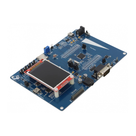
User Manual GD32350R-EVAL Summary GD32350R-EVAL evaluation board uses GD32F350RBT6 as the main controller. As a complete development platform of GD32F3x0 powered by ARM® Cortex™-M4 core, the board supports full range of peripherals. It uses mini-USB interface or AC/DC adapter to supply 5V power. -
Page 8: Getting Started
User Manual GD32350R-EVAL PB14 TSI_G5_IO3 PB13 TSI_G2_IO2 PB12 TSI_G5_IO1 TSI_G2_IO0 TSI_G2_IO1 SPI0_SCK SPI0_MISO SPI0_MOSI TFT_CS TF_CARD_CS TFT_RESET ADC_IN11 HDMI-CEC COMP0_INP COMPARATOR DAC_OUT Getting started The EVAL Board uses mini-USB connecter or AC/DC adapter to get power, the hardware system power is +3.3V. A mini-USB cable and a J-Link tool are necessary to down programs. -
Page 9: Boot Option
User Manual GD32350R-EVAL 4.2. Boot option Figure 4-2 Schematic diagram of boot option Table 4-1 Boot configuration BOOT1 BOOT0 Boot Mode User memory Default System memory Changed by ISP SRAM memory 4.3. Figure 4-3 Schematic diagram of LED function 4.4. -
Page 10: Usart0
User Manual GD32350R-EVAL 4.5. USART0 Figure 4-5 Schematic diagram of USART0 function +3V3 50V/0.1uF C24 50V/0.1uF 50V/0.1uF MAX3232CSE+ JP13 50V/0.1uF 50V/0.1uF USB_VBUS RS232_TX RS232_TX RS232_TX T1IN T1OUT T2IN T2OUT HEADER 3 PA10 RS232_RX RS232_RX R1OUT R1IN R2OUT R2IN 4.6. RS485... -
Page 11: Adc/Dac
User Manual GD32350R-EVAL 4.7. ADC/DAC Figure 4-7 Schematic diagram of ADC/DAC function 4.8. Figure 4-8 Schematic diagram of I2S function I2S_WS I2S_MCK LRCK SCKI I2S_DIN MSEL PA15 DATA I2S_CK MCLK I2S_MCLK +3V3 NRST MDIN I2S_MDIN 16V/10uF,AVX AGND 50V/0.1uF HGND Vcom... -
Page 12: I2C
User Manual GD32350R-EVAL 4.9. Figure 4-9 Schematic diagram of I2C function +3V3 50V/0.1uF 4.7KΩ 4.7KΩ AT24C02C-SSHM-T 4.10. SPI-TF CARD Figure 4-10 Schematic diagram of SPI-TF CARD function SD/LCD_SPI_CLK +3V3 SD/LCD_SPI_MOSI 10KΩ TF_CARD_SOCKET 16V/10uF,AVX +3V3 11 /33... -
Page 13: Spi-Tft Lcd
User Manual GD32350R-EVAL 4.11. SPI-TFT LCD Figure 4-11 Schematic diagram of SPI-TFT LCD function +3V3 +3V3 50V/0.1uF 10KΩ 10KΩ TFT_CS RESET JP10 SD/LCD_SPI_MOSI SD/LCD_SPI_MOSI SDI(MOSI) SD/LCD_SPI_CLK I2S_MDIN HEADER 3 +3V3 JP11 SDO(MISO) SD/LCD_SPI_CLK I2S_MCLK SPI_LCD_Interface HEADER 3 4.12. USBFS Figure 4-12 Schematic diagram of USBFS function 47KΩ... -
Page 14: Cmp
User Manual GD32350R-EVAL 4.13. Figure 4-13 Schematic diagram of CMP function 4.14. HDMI-CEC Figure 4-14 Schematic diagram of HDMI-CEC function +3V3 27KΩ HEADER 2 HDMI-CEC 4.15. Figure 4-15 Schematic diagram of TSI function 13 /33... -
Page 15: Ifrp
User Manual GD32350R-EVAL 4.16. IFRP Figure 4-16 Schematic diagram of IFRP function +3V3 100Ω LED5 KD-03144R 100Ω HS0038B 8050 1KΩ 10V/4.7uF 10KΩ 4.17. Figure 4-17 Schematic diagram of RTC function VBAT +3V3 Battety Vbat select 14 /33... -
Page 16: Gd-Link
User Manual GD32350R-EVAL 4.18. GD-Link Figure 4-18 Schematic diagram of GD-Link function MCU SWD PA0-WKUP +3V3 JP100 PB2/BOOT1 PB3/JTDO L_SWDIO L_TMS/IO PB4/JNTRST L_SWDCK L_TCK/CLK L_TDO/SWO L_TDI 4×1P2.54 L_USB_Ctr L_TReset L_LED1 LED0603 PA10 PB10 L_USB_DM PA11 PB11 L_USB_DP L_LED1 R109 470Ω... -
Page 17: Extension
User Manual GD32350R-EVAL 4.19. Extension Figure 4-19 Schematic diagram of Extension Pin PA15 PA14 PC11 PC10 PC12 BOOT0 +3V3 PC13 PC15 PC14 HEADER 16X2 PA12 PA13 PA10 PA11 PB14 PB15 +3V3 PB12 PB13 PB10 PB11 HEADER 16X2 EXTENTION 16 /33... -
Page 18: Mcu
Learn to use GPIO for controlling the LED Learn to use SysTick to generate 1ms delay GD32350R-EVAL board has four LEDs. The LED1, LED2, LED3 and LED4 are controlled by GPIO. This demo will show how to light the LEDs. 5.1.2. -
Page 19: Gpio_Keyboard_Polling_Mode
Learn to use SysTick to generate 1ms delay GD32350R-EVAL board has four keys and four LEDs. The four keys are Reset key, Tamper key, User key and Wakeup key. The LED1, LED2, LED3 and LED4 are controlled by GPIO. -
Page 20: Usart_Printf
User Manual GD32350R-EVAL will be turned on. Press down the Tamper Key again, LED2 will be turned off. 5.4. USART_Printf 5.4.1. DEMO Purpose This Demo includes the following functions of GD32 MCU: Learn to use GPIO: the Tamper key control the LED ... -
Page 21: Usart_Dma
User Manual GD32350R-EVAL 5.6. USART_DMA 5.6.1. DEMO Purpose This Demo includes the following functions of GD32 MCU: Learn to use the COM transmit and receive using DMA 5.6.2. DEMO Running Result Jump JP13 to USART, then download the program < 06_USART_DMA > to the EVAL board and run. -
Page 22: Demo Running Result
GD32F350R_EVAL boards, one board as a sender, the other as a receiver. First connect two GD32350R-EVAL boards through RS485 line A and B, and then download the program < 07_RS485_Test > to the board for running. When press... -
Page 23: Demo Running Result
<08_ADC_conversion_triggered_by_timer> GD32350R-EVAL board, adjust the adjustable potentiometer knob to change the analog input. The ADC, which is triggered by TIMER1 CH1 event, will convert the analog input, and you will see the result, a voltage curve, on the LCD. The curve adjusts with the analog input. -
Page 24: I2C_Eeprom
User Manual GD32350R-EVAL 5.11. I2C_EEPROM 5.11.1. DEMO Purpose This Demo includes the following functions of GD32 MCU: Learn how to use the master transmitting mode of the I2C module Learn how to use the master receiving mode of the I2C module ... -
Page 25: Spi_Tf_Card_Block_Operation
User Manual GD32350R-EVAL 5.12. SPI_TF_Card_Block_Operation 5.12.1. DEMO Purpose This Demo includes the following function of GD32 MCU: Learn how to use SPI to block read and write from TF card In this demo, the SPI interface is used for reading from and writing to TF card. Write to TF card with 0 to 255, a total of 2048 bytes directly. -
Page 26: Spi_Tf_Card_Fatfs_Operation
User Manual GD32350R-EVAL 5.13. SPI_TF_Card_FATFS_Operation 5.13.1. DEMO Purpose This Demo includes the following function of GD32 MCU: Learn how to use SPI to read and write from TF card with FATFS In this demo, the SPI interface is used for reading from and writing to TF card. Make sure the TF card has FAT file system. -
Page 27: Spi_Tft_Lcd_Driver
Learn how to use SPI to drive TFT LCD screen and display GD32350R-EVAL board has a TFT LCD screen which supports SPI interface. In this demo, tests of font, number, draw and color are displayed on the LCD screen respectively. -
Page 28: Hdmi-Cec_Hostslavecommunication
User Manual GD32350R-EVAL 5.15. HDMI-CEC_HostSlaveCommunication 5.15.1. DEMO Purpose This Demo includes the following functions of GD32 MCU: Learn the communication function of HDMI-CEC In the process of communication, the sender sends data to receiver through the key interrupt, the receiver for receiving data in the CEC interrupt. The entire communication process does not make the error processing. -
Page 29: I2S_Audio_Player
Learn to use I2S module to output audio file GD32350R-EVAL board integrates the I2S (Inter-IC Sound) module, and the module can communicate with external devices using the I2S audio protocol. This Demo mainly shows how to use the I2S interface of the board for audio output. -
Page 30: Pmu_Sleep_Wakeup
User Manual GD32350R-EVAL 5.18. PMU_sleep_wakeup 5.18.1. DEMO Purpose This Demo includes the following functions of GD32 MCU: Learn to use the USART receive interrupt to wake up the PMU from sleep mode 5.18.2. DEMO Running Result Download the program < 18_PMU_sleep_wakeup > to the EVAL board, connect serial cable to EVAL_COM. -
Page 31: Demo Running Result
DEMO Running Result Use the DuPont line to connect the TIMER0_CH0 (PA8) and LED1 (PC10), and then download the program <21_TIMER_Breath_LED> to the GD32350R-EVAL board and run. PA8 should not be reused by other peripherals. When the program is running, you can see LED1 lighting from dark to bright gradually and then gradually darken, ad infinitum, just like breathing as rhythm. -
Page 32: Usbd_Keyboard
User Manual GD32350R-EVAL This demo includes the following functions of GD32 MCU: Learn how to use the USBFS peripheral Learn how to implement USB CDC device EVAL board has one USBFS interface. In this demo, the EVAL board is enumerated as an USB virtual COM port, which was shown in device manager of PC as below. -
Page 33: Usb_Host
User Manual GD32350R-EVAL characters (‘b’, ‘a’ and ‘c’). In addition, the demo also supports remote wakeup which is the ability of a USB device to bring a suspended bus back to the active condition, and the wakeup key is used as the remote wakeup source. -
Page 34: Usbh_Msc_Host
User Manual GD32350R-EVAL If a mouse has been attached, the user will see the information of mouse enumeration. First pressing the user key will see the inserted device is mouse, and then moving the mouse will show the position of mouse and the state of button in the screen. - Page 35 X-ON Electronics Largest Supplier of Electrical and Electronic Components Click to view similar products for category: Development Boards & Kits - Other Processors Click to view products by manufacturer: Gigadevice Other Similar products are found below : KIT_AURIX_TC233LP_TRB EVB-MEC1418MECC SPC56XVTOP-M ADZS-BF506F-EZLITE ADZS-SADA2-BRD 20-101-1252 T1023RDB-PC 20-101-1267 T1042D4RDB-PA ML610Q174 REFERENCE BOARD MPC574XG-MB BSC9132QDS C29XPCIE-RDB KIT_TC1793_SK CC-ACC-18M433 P1010RDB-PB P1020RDB-PD P2020COME-DS-PB STM8S/32-D/RAIS T4240RDB-PB TRK-USB- MPC5604B TWR-56F8200 CY3674 SPC58XXADPT176S MAX1464EVKIT TRK-MPC5606B RTE510Y470TGB00000R STM8128-...
Need help?
Do you have a question about the GD32350R-EVAL and is the answer not in the manual?
Questions and answers