Table of Contents
Advertisement
Quick Links
Advertisement
Table of Contents

Related Manuals for GigaDevice Semiconductor GD32450I-EVAL


Summary of Contents for GigaDevice Semiconductor GD32450I-EVAL
- Page 1 GigaDevice Semiconductor Inc. GD32450I-EVAL User Manual...
-
Page 2: Table Of Contents
User Manual GD32450I-EVAL Table of Contents 目录 Table of Contents ..........................1 List of Tables ........................... 3 Summary ..........................4 Function Pin Assign ........................ 4 Getting started ......................... 8 Hardware layout overview ....................... 9 Power ..........................9 Boot ............................ 9 LED............................. - Page 3 User Manual GD32450I-EVAL ADC0_ADC1_Follow_up_mode ..................22 ADC0_ADC1_Regular_Parallel_mode ................23 5.10 DAC_Output_Voltage_Value .................... 24 5.11 I2C_EEPROM ........................24 5.12 SPI_QSPI_Flash ......................26 5.13 I2S_Audio_Player ......................27 5.14 EXMC_SDRAM ........................ 28 5.15 EXMC_SDRAM_DeepSleep ..................... 28 5.16 EXMC_NandFlash ......................29 5.17 SDIO_SDCardTest ......................30 5.18...
-
Page 4: List Of Tables
User Manual GD32450I-EVAL List of Tables Table 1 Function pin assign ........................... 4 Table 2 Revision history ..........................51 3/ 51... -
Page 5: Summary
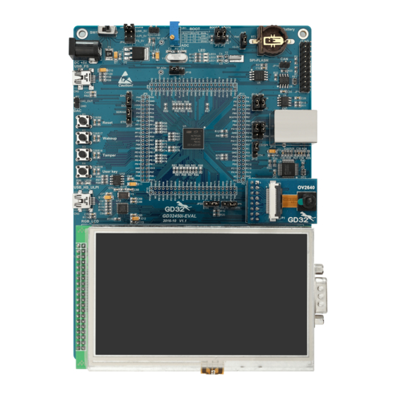
GD32450I-EVAL Summary GD32450I-EVAL uses GD32F450IGH6 as the main controller. It uses Mini USB interface or DC-005 connector to supply 5V power. SWD, Reset, Boot, User button key, LED, CAN, I2C, I2S, USART, RTC, LCD, SPI, ADC, DAC, EXMC, CTC, SDIO, DCI, ENET, USBFS, USBHS, GD-Link and Extension Pins are also included. - Page 6 User Manual GD32450I-EVAL EXMC_NWAIT EXMC_NCE1 PD11 EXMC_CLE PD12 EXMC_ALE PD14 EXMC_D0 PD15 EXMC_D1 EXMC_D4 EXMC_D5 EXMC_D6 PE10 EXMC_D7 EXMC_SDNE0 EXMC_SDCKE0 EXMC_D2 EXMC_D3 EXMC_D13 EXMC_D14 PD10 EXMC_D15 PD14 EXMC_D0 PD15 EXMC_D1 EXMC_NBL0 EXMC_NBL1 EXMC_D4 EXMC_D5 EXMC_D6 PE10 EXMC_D7 PE11 EXMC_D8 SDRAM...
- Page 7 User Manual GD32450I-EVAL EXMC_A11 EXMC_A12 EXMC_A14 EXMC_A15 EXMC_SDCLK PG15 EXMC_NCAS EXMC_SDNWE SDIO_CMD PC12 SDIO_CK SDIO_D0 SDIO SDIO_D1 PC10 SDIO_D2 PC11 SDIO_D3 DCI_I2C0_SCL DCI_I2C0_SDA DCI_HSYNC DCI_VSYNC DCI_PIXCLK DCI_XCLK DCI_D7 DCI_D6 DCI_D5 PC11 DCI_D4 DCI_D3 DCI_D2 DCI_D1 DCI_D0 LCD_Touch_PENIRQ LCD_SPI4_MOSI LCD_SPI4_MISO LCD_SPI4_SCK...
- Page 8 User Manual GD32450I-EVAL LCD_G0 LCD_G1 PH13 LCD_G2 PH14 LCD_G3 PH15 LCD_G4 LCD_G5 LCD_G6 LCD_G7 LCD_B0 PG12 LCD_B1 PG10 LCD_B2 PG11 LCD_B3 LCD_B4 LCD_B5 LCD_B6 LCD_B7 LCD_CLK PI10 LCD_HSYNC LCD_VSYNC ETH_RMII_REF_CLK ETH_MDIO ETH_RMII_CRS_DV PG11 ETH_RMII_TX_EN PG13 ETH_RMII_TXD0 Ethernet PG14 ETH_RMII_TXD1 ETH_MDC...
-
Page 9: Getting Started
User Manual GD32450I-EVAL USB_HS_ULPI_D1 USB_HS_ULPI_D0 Getting started The EVAL board uses Mini USB connecter or DC-005 connector to get power DC +5V, which is the hardware system normal work voltage. Three kinds of different USB power supply which are USB_FS, USB_HS_ULPI, GD-Link can be chosen through JP4. A J-Link tool or GD-Link on board is necessary in order to download and debug programs. -
Page 10: Hardware Layout Overview
User Manual GD32450I-EVAL Hardware layout overview Power Boot BOOT0 +3V3 10KΩ BOOT0 BOOT1 +3V3 10KΩ BOOT1 BOOT1 BOOT0 Boot Mode User memory System memory SRAM memory LED1 LED1 470Ω LED0603 LED2 LED2 470Ω LED0603 PF10 LED3 LED3 470Ω LED0603 9/ 51... -
Page 11: Key
User Manual GD32450I-EVAL USART USART0 +3V3 50V/0.1uF 50V/0.1uF 50V/0.1uF 50V/0.1uF 50V/0.1uF T1IN T1OUT USART0_TX RS232_TX0 T2IN T2OUT R1OUT R1IN USART0_RX RS232_RX0 R2OUT R2IN MAX3232CSE+ Short JP5(1,2)for USART0 function Short JP5(2,3)for USB_FS function USART0_TX USB_FS_VBUS COM1 HEADER 3 PA10 USART0_RX 10/ 51... -
Page 12: Adc
User Manual GD32450I-EVAL PC1 is an AFIO, please refer to ETHNET Schematic for right config 10KΩ I2S1_SD +3V3 SDIN AOUTR I2S1_CK 470Ω SCLK I2S1_WS 50V/0.1uF 16V/3.3uF,AVX LRCK I2S1_MCK MCLK AOUTL FILT+ 470Ω HeadPhone CS4344 16V/3.3uF,AVX 10KΩ 50V/0.1uF 16V/10uF,AVX 16V/10uF,AVX I2S1_SD I2S1_CK 0Ω... -
Page 13: Spi
User Manual GD32450I-EVAL 4.10 Standard & Quad SPI Flash Short JP12(1,2) for Ethnet function Short JP12(2,3) for SPI & TLI function JP12 RMII_TX_EN PG11 PG12 SPI5_MISO_IO1 SPI5_HOLD_IO3 PG10 SPI5_WP_IO2 SPIFlash_CS +3V3 +3V3 HEADER 3 50V/0.1uF Short JP13(1,2) for Ethnet function 10KΩ... -
Page 14: Ethernet
User Manual GD32450I-EVAL 4.12 Ethernet Ethernet PG11、PG13、PG14 are AFIOs, please refer to SPI schematic for right config PG11 RMII_TX_EN Short JP17(1,2) for Ethnet function Short JP18(1,2) for Ethnet function PG13 RMII_TXD0 Short JP17(2,3) for SDRAM function Short JP18(2,3) for I2S function... -
Page 15: Nand Flash
User Manual GD32450I-EVAL 4.14 NAND Flash Nand Flash +3V3 +3V3 EXMC_D7 VDD1 PD14 EXMC_D0 PD11 EXMC_A16 EXMC_D6 VDD2 PD15 EXMC_D1 PD12 EXMC_A17 EXMC_D5 50V/0.1uF 50V/0.1uF EXMC_D2 EXMC_NCE1 EXMC_D4 VSS1 EXMC_D3 EXMC_NOE EXMC_D3 VSS2 EXMC_D4 EXMC_NWE EXMC_D2 EXMC_D5 EXMC_NWAIT EXMC_D1 EXMC_D6... -
Page 16: Dci
User Manual GD32450I-EVAL 4.16 DCI 8bit DCI_PIXCLK SDIO_DAT1 I2S1_MCK DCI_D3 SDIO_DAT0 SDIO_DAT2 PC11 DCI_I2C0_SDA DCI_D2 +3V3 JP27 DCI_D4 DCI_I2C0_SCL DCI_VSYNC DCI_I2C0_SCL DCI_I2C0_SDA DCI_PIXCLK DCI_VSYNC DCI_HSYNC DCI_D5 DCI_PIXCLK DCI_XCLK PC11 DCI_D4 0Ω DCI_D7 DCI_D6 Short JP23(1,2) for DAC function DCI_D3 0Ω... -
Page 17: Usbfs
User Manual GD32450I-EVAL 4.18 USBFS "VBUS_FS_5V control(active HIGH)" see USB_HS sch ematic PD13----> VBUS_FS_5V 16V/10uF,AVX PA9 is AFIO, please refer to USART schematic for right config USB_FS_VBUS R120 10KΩ VBUS PA11 USB_FS_DM 22Ω PA12 USB_FS_DP 22Ω Shield Mini_USB 1MΩ 50V/4.7nF 4.19... -
Page 18: Extension
Learn to use GPIO control the LED Learn to use SysTick to generate 1ms delay GD32450I-EVAL board has three LEDs. The LED1, LED2 and LED3 are controlled by GPIO. This demo will show how to light the LEDs. 17/ 51... -
Page 19: Gpio_Keyboard_Polling_Mode
Learn to use GPIO control the LED and the KEY Learn to use SysTick to generate 1ms delay GD32450I-EVAL board has four keys and three LEDs. The four keys are Reset key, Tamper key, Wakeup key and User key. The LED1, LED2 and LED3 are controlled by GPIO. -
Page 20: Usart_Printf
User Manual GD32450I-EVAL This demo will show how to use the EXTI interrupt line to control the LED1.When press down the Tamper Key, it will produce an interrupt. In the interrupt service function, the demo will toggle LED1. 5.3.2 DEMO Running Result Download the program <03_GPIO_KeyBoard_Interrupt_mode>... -
Page 21: Usart_Dma
User Manual GD32450I-EVAL 5.5.2 DEMO Running Result Download the program < 05_USART_Echo_Interrupt_mode > to the EVAL board, jump the JP5 to USART with the jumper cap and connect serial cable to EVAL_COM1. Firstly, all the LEDs are turned on and off for test. Then, the EVAL_COM1 sends the tx_buffer... -
Page 22: Adc_Temperature_Vrefint_Vbat
DEMO Running Result Jump the JP5 to USART with the jumper cap, and then download the program <07_ADC_Temperature_Vrefint_Vbat> to the GD32450I-EVAL board. Connect serial cable to EVAL_COM1, open the HyperTerminal. When the program is running, HyperTerminal display the value of temperature, internal... -
Page 23: Adc0_Adc1_Follow_Up_Mode
DEMO Running Result Jump the JP5 to USART with the jumper cap, and then download the program <08_ADC0_ADC1_Follow_up_mode> to the GD32450I-EVAL board. Connect serial cable to EVAL_COM1, open the HyperTerminal. PC5 pin connect to the external voltage input. PC3 is the output voltage of the slide rheostat VR1 on board. Keep PC5 pin should not be reused by other peripherals. -
Page 24: Adc0_Adc1_Regular_Parallel_Mode
DEMO Running Result Jump the JP5 to USART with the jumper cap, and then download the program <09_ADC0_ADC1_Regular_Parallel_mode> to the GD32450I-EVAL board. Connect serial cable to EVAL_COM1, open the HyperTerminal. PC5 pin connect to the external voltage input. PC3 is the output voltage of the slide rheostat VR1 on board. Keep PC5 pin should not be reused by other peripherals. -
Page 25: Dac_Output_Voltage_Value
User Manual GD32450I-EVAL ADC1 stored in adc_value [0] and adc_value [1]. 5.10 DAC_Output_Voltage_Value 5.10.1 DEMO Purpose This demo includes the following functions of GD32 MCU: Learn to use DAC to output voltage on DAC0 output 5.10.2 DEMO Running Result... - Page 26 User Manual GD32450I-EVAL 5.11.2 DEMO Running Result Jump the JP5 to USART with the jumper cap, and download the program <11_I2C_EEPROM> to the EVAL board and run. Connect serial cable to COM1, and open the HyperTerminal to show the print message.
-
Page 27: Spi_Qspi_Flash
Learn to use the Quad-SPI mode of SPI unit to read and write NOR Flash with the SPI interface GD32450I-EVAL board integrates SPI5 module with Quad-SPI mode and the mode can communicate with external NOR Flash devices. The SPI NOR FLASH is a serial FLASH memory chip GD25Q16B which size is 16Mbit, the chip supports standard SPI and quad SPI operation instructions. -
Page 28: I2S_Audio_Player
Learn to use I2S module to output audio file Parsing audio files of wav format GD32450I-EVAL board integrates the I2S(Inter-IC Sound) module, and the module can communicate with external devices using the I2S audio protocol. This Demo mainly shows how to use the I2S interface of the board for audio output. -
Page 29: Exmc_Sdram
5.14.2 DEMO Running Result GD32450I-EVAL board has EXMC module to control SDRAM. Before running the demo, JP17 must be fitted to SDRAM, JP5 must be fitted to USART. Download the program <14_EXMC_SDRAM> to the EVAL board. This demo shows the write and read operation process of SDRAM memory by EXMC module. -
Page 30: Exmc_Nandflash
5.16.2 DEMO Running Result GD32450I-EVAL board has EXMC module to control NAND flash. Before running the demo, JP5 must be fitted to USART. Download the program <16_EXMC_NandFlash> to the EVAL board. This demo shows the write and read operation process of NAND flash memory by EXMC module. -
Page 31: Sdio_Sdcardtest
Learn to use SDIO to erase, lock and unlock a SD card GD32450I-EVAL board has a secure digital input/output interface (SDIO) which defines the SD/SD I/O /MMC CE-ATA card host interface. This demo will show how to use SDIO to operate on SD card. -
Page 32: Can_Network
Learn to use the CAN0 communication between two boards GD32450I-EVAL development board integrates the CAN(Controller Area Network) bus controller, which is a common industrial control bus. CAN bus controller follows the CAN bus protocol of 2.0 A and 2.0 B. This demo mainly shows how to communicate between two EVAL boards through CAN0. -
Page 33: Rcu_Clock_Output
User Manual GD32450I-EVAL 5.19 RCU_Clock_Output 5.19.1 DEMO Purpose This demo includes the following functions of GD32 MCU: Learn to use GPIO control the LED Learn to use the clock output function of RCU Learn to communicate with PC by USART 5.19.2... -
Page 34: Pmu_Sleep_Wakeup
It can automaticly adjust the trim value to provide a precise IRC48M clock. 5.20.2 DEMO Running Result Download the program <20_CTC_Calibration > to the GD32450I-EVAL board and run. The LED1 will turn on if the internal 48MHz RC oscillator (IRC48M) clock trim is OK. 5.21 PMU_sleep_wakeup 5.21.1... -
Page 35: Timer_Breath_Led
DEMO Running Result Use the DuPont line to connect the TIMER1_CH2 (PB10) and LED1 (PE2), and then download the program <23_TIMER_Breath_LED> to the GD32450I-EVAL board and run. PB10 should not be reused by other peripherals, such as USB_HS_ULPI. When the program is running, you can see LED1 lighting from dark to bright gradually and then gradually darken, ad infinitum, just like breathing as rhythm. -
Page 36: Tli_Ipa
User Manual GD32450I-EVAL 5.24 TLI_IPA 5.24.1 DEMO Purpose This demo includes the following functions of GD32 MCU: Learn to use TLI to control LCD for displaying different images Learn to use IPA to process image data 5.24.2 DEMO Running Result Jump the JP12 to LCD, and download the program <24_TLI_IPA>... -
Page 37: Trng_Get_Random
DEMO Running Result Connect jumper JP19,JP21,JP22,JP23 to DCI, jumper JP12 to LCD, jumper JP17 to SDRAM. Download the program<25_DCI_OV2640>to the GD32450I-EVAL board, the correct installation of LCD display and OV2640 camera to the development board. After power on, you can observe the capture image of camera displayed on the LCD screen, you can press the user key to take photo and press tamper key to display photo. -
Page 38: Enet
User Manual GD32450I-EVAL Learn to use TRNG generate the random number Learn to communicate with PC by USART 5.26.2 DEMO Running Result Jump the JP5 to USART with the jumper cap, and download the program <26_TRNG_Get_Random> to the EVAL board and run. Connect serial cable to EVAL_COM1, open the serial terminal tool supporting hex format communication. - Page 39 Learn how to use DHCP to allocate ip address automatically This demo is based on the GD32450I-EVAL board, it shows how to configure the enet peripherals to send and receive frames in normal mode and use lwip tcp/ip stack to realize ping, telnet and server/client functions.
- Page 40 User Manual GD32450I-EVAL client: Using Network assistant software, configure to use udp protocol, using 1025 port, and when send something through the assistant, users can see the echo reply from the board: Open the DHCP function in main.h, using a router to connect the board with the pc, users can see the automatic allocated ip address of the board from the HyperTerminal.
- Page 41 User Manual GD32450I-EVAL This demo is based on the GD32450I-EVAL board, it shows how to configure the enet peripherals to send and receive frames in normal mode and use lwip tcp/ip stack to realize ping, telnet and server/client functions. JP12, JP13, JP17, JP18, JP20, JP22 must be fitted. JP5 jump to Usart.
- Page 42 User Manual GD32450I-EVAL Using Network assistant software, configure the pc side to tcp server, using 1026 port, press the Tamper key, and when send something through the assistant, users can see the echo reply from the client: Using Network assistant software, configure to use udp protocol, using 1025 port, and...
- Page 43 Learn to handle with received packet in polling mode and in interrupt mode This demo is based on the GD32450I-EVAL board, it shows how to configure the enet peripherals to send and receive frames in normal mode and use lwip tcp/ip stack to realize webserver application.
- Page 44 User Manual GD32450I-EVAL The LED control page shows as below: The ADC monitor page shows as below: Open the DHCP function in main.h, using a router to connect the board, and use the 43/ 51...
-
Page 45: Usb_Device
GD32450I-EVAL board has four keys and one USB_FS interface. The four keys are Reset key, Wakeup key, User key and Tamper key. In this demo, the GD32450I-EVAL board is enumerated as an USB Keyboard, which uses the native PC Host HID driver, as shown below. - Page 46 User Manual GD32450I-EVAL - Push the Wakeup key - If PC is ON, remote wakeup is OK, else failed. 5.28.2 MSC_Udisk DEMO Purpose This demo includes the following functions of GD32 MCU: Learn how to use the USBFS/USBHS peripheral mode ...
- Page 47 User Manual GD32450I-EVAL According to the VBUSIG bit in USBFS_GCCFG register, user can decide whether or not to jump JP5 to USB_FS if user use USBFS core. Then connect the EVAL board to the PC through USB cable to the USB_FS connector if user use USBFS core or the USB_HS_ULPI connector if use USBHS core.
-
Page 48: Usb_Host
Learn the operation between the HID host and the keyboard device GD32450I-EVAL board integrates the USBFS module, and the module can be used as a USB device, a USB host or an OTG device. This demo mainly shows how to use the USBFS as a USB HID host to communicate with external USB HID device. - Page 49 User Manual GD32450I-EVAL First pressing the user key will see the inserted device is mouse, and then moving the mouse will move the 'x' in the LCD screen and pressing the button will show the magenta color rectangle in the LCD screen.
- Page 50 User Manual GD32450I-EVAL First pressing the user key will see the inserted device is keyboard, and then pressing the keyboard will print the char of the button in the LCD screen. 5.29.2 MSC_Host DEMO Purpose 49/ 51...
- Page 51 Learn the operation between the MSC host and the Udisk GD32450I-EVAL board integrates the USBFS and USBHS module, and the modules can be used as a USB device, a USB host or an OTG device. This demo mainly shows how to use the USBFS or the USBHS as a USB MSC host to communicate with external Udisk.
-
Page 52: Revision History
User Manual GD32450I-EVAL Revision history Table 2 Revision history Revision No. Description Date Initial Release Oct. 19, 2016 51/ 51...
Need help?
Do you have a question about the GD32450I-EVAL and is the answer not in the manual?
Questions and answers