
Subscribe to Our Youtube Channel
Related Manuals for Phoenix Contact SD FLASH 512MB MODULAR MUX


Summary of Contents for Phoenix Contact SD FLASH 512MB MODULAR MUX
- Page 1 Installing and starting up the SD FLASH 512MB MODULAR MUX multiplexer system User manual...
- Page 2 UM EN SD FLASH 512MB MODULAR MUX, Revision 03 2021-02-22 This user manual is valid for: Designation Revision Order No. SD FLASH 512MB MODULAR MUX 2701872 PHOENIX CONTACT GmbH & Co. KG • Flachsmarktstraße 8 • 32825 Blomberg • Germany phoenixcontact.com...
-
Page 3: Table Of Contents
Foreseeable misuse ................6 1.3.3 Modifications to the products ..............6 Safety notes ......................6 Description of the SD FLASH 512MB MODULAR MUX multiplexer system ......8 Hardware and software requirements..............8 Structure of the multiplexer system................ 8 Startup ............................9 Connecting stations via Ethernet cable or wireless network ........ - Page 4 SD FLASH 512MB MODULAR MUX Web interface ...........................29 “General” start page .................... 29 “State of ILC 131 ETH” page ................30 4.2.1 “Set date and time of ILC 131 ETH” page ..........31 4.2.2 “Set IP Address of ILC 131 ETH” page ..........32 “Interbus”...
-
Page 5: For Your Safety
The use of products described in this user manual is oriented exclusively to electrically skilled persons or persons instructed by them. The users must be familiar with the relevant safety concepts of automation technology as well as applicable standards and other regu- lations. 5 / 56 PHOENIX CONTACT 105752_en_03... -
Page 6: Field Of Application Of The Product
1.3.1 Intended use The SD FLASH 512MB MODULAR MUX SD card is intended for creation of a multiplexer system in combination with the ILC 131 ETH controller. Two of these SD cards, with two ILC 131 ETHs and the individually required input and out- put terminals, form a multiplexer system that requires no programming. - Page 7 NOTE: Damage due to modifications to the SD card If you modify files on the SD FLASH 512MB MODULAR MUX SD card, you damage the application contained on the SD card. If this is the case, the SD card can no longer be used for creating a multiplexer system.
-
Page 8: Description Of The Sd Flash 512Mb Modular Mux Multiplexer System
Section “Technical data and ordering data” on page Structure of the multiplexer system Using two SD FLASH 512MB MODULAR MUX SD cards, it is possible to create a multi- plexer system consisting of two ILC 131 ETH Inline controllers. You do not need to program the Inline controllers. -
Page 9: Startup
Inserting SD cards into the Inline controllers • Lightly push an SD card into the SD card holder of each Inline controller until it snaps into place. >Click< Figure 3-1 Inserting the SD card 9 / 56 PHOENIX CONTACT 105752_en_03... -
Page 10: Connecting The Inline Controllers To Each Other
SD FLASH 512MB MODULAR MUX The SD cards contain the multiplexer software. They remain in the Inline controllers during operation. Write protection for the SD cards must not be activated because data is saved to the SD cards. 3.1.3 Connecting the Inline controllers to each other The two Inline controllers are connected to each other via their respective Ethernet connec- tions. -
Page 11: Configuring Master And Slave
BSA PF MAC Addr.: xx.xx.xx.xx MAC Addr.: xx.xx.xx.xx AUTOMATIONWORX AUTOMATIONWORX MRESET MRESET STOP STOP RUN / PROG RUN / PROG RESET RESET Jumper 105752A003 Figure 3-4 Configuring the Inline controllers as master and slave 11 / 56 PHOENIX CONTACT 105752_en_03... -
Page 12: Connection Assignment
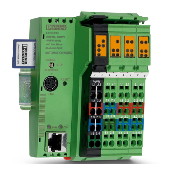
SD FLASH 512MB MODULAR MUX The digital inputs are only used for configuration purposes, they are not available as I/O ports. Connection assignment of the supply, actuators and sensors Figure 3-5 Terminal points of Inline connectors Power connector 1, PWR... -
Page 13: Mounting I/O Terminals
BSA PF MAC Addr.: xx.xx.xx.xx MAC Addr.: xx.xx.xx.xx AUTOMATIONWORX AUTOMATIONWORX MRESET MRESET STOP STOP RUN / PROG RUN / PROG RESET RESET 105752A004 Figure 3-6 Connecting I/O terminals side by side to the Inline controllers 13 / 56 PHOENIX CONTACT 105752_en_03... -
Page 14: Connecting The Supply Voltages
SD FLASH 512MB MODULAR MUX 3.1.6 Connecting the supply voltages Only use power supplies that are suitable for operation with capacitive loads (increased inrush current). Additional information on the supply voltage can be found in the “Installing and operating the ILC 131 ETH, ILC 151 ETH, ILC 171 ETH 2TX, ILC 191 ETH 2TX, ILC 131 ETH/XC and ILC 151 ETH/XC Inline controllers”... -
Page 15: Reading In The Bus Configuration
Inline controllers is established automatically. The multiplexer system switches to normal operating state. The pending I/O signals are transmitted. The LEDs Q1 to Q4 are used to indicate possible errors, see Section A 1 on page 15 / 56 PHOENIX CONTACT 105752_en_03... -
Page 16: Using Safetybridge Technology For The Multiplexer System In The Wireless Network
Additional information on how to use the multiplexer system in conjunction with Safety- Bridge Technology can be found in the AH EN SD FLASH 512MB MODULAR MUX SAFETYBRIDGE application note. The application note can be downloaded at phoenixcontact.net/product/2701872. Integrating the multiplexer system into an Ethernet... -
Page 17: Inserting Sd Cards Into The Inline Controllers
Configure an Inline controller as master. Wire 24 V DC to input I1 (terminal point 1.1 to 1.2). To do this, insert a jumper as shown in Figure 3-11. The second Inline controller will then automatically be configured as slave. The slave does not receive any signal at input I1. 17 / 56 PHOENIX CONTACT 105752_en_03... - Page 18 SD FLASH 512MB MODULAR MUX Slave Master ILC 131 ETH ILC 131 ETH Order-No.: 2700973 Order-No.: 2700973 HW/FW: xx/xxx HW/FW: xx/xxx RDY FAIL BSA PF RDY FAIL BSA PF MAC Addr.: xx.xx.xx.xx MAC Addr.: xx.xx.xx.xx AUTOMATIONWORX AUTOMATIONWORX MRESET MRESET STOP...
-
Page 19: Configuring The Behavior After A Voltage Reset
Wiring 24 V DC to input I5 (terminal point 3.1 to 3.2) causes the IP addresses of the Inline controllers to be kept after a voltage reset. When this wiring is not in place, the default IP addresses will be automatically assigned to the Inline controllers after a voltage reset. 19 / 56 PHOENIX CONTACT 105752_en_03... - Page 20 SD FLASH 512MB MODULAR MUX Slave Master ILC 131 ETH ILC 131 ETH Order-No.: 2700973 Order-No.: 2700973 HW/FW: xx/xxx HW/FW: xx/xxx RDY FAIL BSA PF RDY FAIL BSA PF MAC Addr.: xx.xx.xx.xx MAC Addr.: xx.xx.xx.xx AUTOMATIONWORX AUTOMATIONWORX MRESET MRESET STOP...
-
Page 21: Connecting The Inline Controllers To A Pc
Connecting the Inline controllers to a PC • When you have assigned the master IP address as described in Sections 3.3.6 to 3.3.7, go back to Section 3.3.5 and repeat the instructions in Sections 3.3.5 3.3.7 for the slave. 21 / 56 PHOENIX CONTACT 105752_en_03... -
Page 22: Connecting The Voltage Supply
SD FLASH 512MB MODULAR MUX 3.3.6 Connecting the voltage supply Only use power supplies that are suitable for operation with capacitive loads (increased inrush current). Additional information on the supply voltage can be found in the “Installing and operating the ILC 131 ETH, ILC 151 ETH, ILC 171 ETH 2TX, ILC 191 ETH 2TX, ILC 131 ETH/XC and ILC 151 ETH/XC Inline controllers”... -
Page 23: Assigning The Ip Address For The Inline Controller
Click the “ILC 131 ETH” button. • In the window that opens, click the “Set IP Address” button. The “Set IP Address of ILC 131 ETH” page for assigning an IP address to the Inline control- (Figure 3-17) opens. 23 / 56 PHOENIX CONTACT 105752_en_03... - Page 24 SD FLASH 512MB MODULAR MUX Figure 3-17 “Set IP Address of ILC 131 ETH” page • In the “Local PLC” area, set the IP address, the subnet mask and the gateway address for the Inline controller for which you have opened the multiplexer web interface.
-
Page 25: Mounting I/O Terminals
BSA PF MAC Addr.: xx.xx.xx.xx MAC Addr.: xx.xx.xx.xx AUTOMATIONWORX AUTOMATIONWORX MRESET MRESET STOP STOP RUN / PROG RUN / PROG RESET RESET 105752A011 Figure 3-18 Connecting I/O terminals side by side to the Inline controllers 25 / 56 PHOENIX CONTACT 105752_en_03... -
Page 26: Connecting The Inline Controllers To The Network
SD FLASH 512MB MODULAR MUX 3.3.9 Connecting the Inline controllers to the network After assigning the IP addresses to the Inline controllers (see Sections 3.3.5 to 3.3.7), you can connect the Inline controllers to the network. • Connect each Inline controller to the network using an Ethernet cable (Figure 3-19). -
Page 27: Defining The Operating State Of The Application Program
IP addresses. To prevent IP addresses from being reset, the behavior after a volt- age reset must be configured as described in Section 3.3.4. For information on diagnostic and status indicators of the Inline controllers, please refer Section A 27 / 56 PHOENIX CONTACT 105752_en_03... -
Page 28: Reading In The Bus Configuration
SD FLASH 512MB MODULAR MUX 3.3.11 Reading in the bus configuration If you subsequently modify a bus configuration that has been read in automatically, the bus configuration must be read in again. You need to manually initiate the reading process for the bus configuration. -
Page 29: Web Interface
On the “General” start page of the web interface, you will find four buttons enabling you to access other web interface pages. These pages are described in Sections to 4.5. The “Performance” button is only displayed for the master. 29 / 56 PHOENIX CONTACT 105752_en_03... -
Page 30: State Of Ilc 131 Eth" Page
SD FLASH 512MB MODULAR MUX “State of ILC 131 ETH” page On the “State of ILC 131 ETH” page, you will find current information on the Inline controller. Figure 4-2 Web interface: “State of ILC 131 ETH” page On the “State of ILC 131 ETH” page, you will find two buttons enabling you to access other web interface pages. -
Page 31: Set Date And Time Of Ilc 131 Eth" Page
To transfer the modified system time to the Inline controller, click the “Send” button. The “Home” button takes you back to the “General” start page (see Section 4.1). The “Back” button takes you back to the “State of ILC 131 ETH” page (see Section 4.2). 31 / 56 PHOENIX CONTACT 105752_en_03... -
Page 32: Set Ip Address Of Ilc 131 Eth" Page
SD FLASH 512MB MODULAR MUX 4.2.2 “Set IP Address of ILC 131 ETH” page On the “Set IP Address of ILC 131 ETH” page, you can modify the IP address of the Inline controller. Figure 4-4 Web interface: “Set IP Address of ILC 131 ETH” page •... -
Page 33: Interbus" Page
On the “Interbus” page, you will find current information on the connected INTERBUS net- work. Figure 4-5 Web interface: “Interbus” page The “Back” button takes you back to the “General” start page (see Section 4.1). 33 / 56 PHOENIX CONTACT 105752_en_03... -
Page 34: Multiplexer" Page
SD FLASH 512MB MODULAR MUX “Multiplexer” page On the “Multiplexer” page, you will find diagnostic information on the multiplexer system. Figure 4-6 Web interface: “Multiplexer” page The “Back” button takes you back to the “General” start page (see Section 4.1). -
Page 35: Diagnostic Error Codes
“ACTIVATE_CONFIGURATION” not executed 0008 “START_DATA_TRANSFER” not executed C340 Error when comparing the two bus systems (master only), error message of “FB_Connection” block. The additional error codes “ADD ERROR CODE” provide more information on this error message. 35 / 56 PHOENIX CONTACT 105752_en_03... - Page 36 SD FLASH 512MB MODULAR MUX Table 4-1 Diagnostic error codes Error code Meaning ADD ERROR CODE Meaning 0000 No error has occurred 0001 Timeout during connection establishment 0002 The connection is interrupted. 0003 Manual acknowledgment required 0004hex SafetyBridge communication breakdown 0101 The bus length of the master is greater than the bus length of the slave.
-
Page 37: Performance Of The Data Transfer" Page
Table 4-2 Values displayed under “Read/Write Performance” Value Meaning Read/Write Cycles Number of read and write cycles between master and slave Read/Write Cycle MIN Shortest cycle time Read/Write Cycle MAX Longest cycle time 37 / 56 PHOENIX CONTACT 105752_en_03... -
Page 38: Values Displayed Under "Read/Write Performance
SD FLASH 512MB MODULAR MUX Table 4-2 Values displayed under “Read/Write Performance” Value Meaning Read/Write Cycle Average Average cycle time within the current time interval (“Interval time”, see below) You can reset the values displayed under “Read/Write Performance” by clicking the “Reset”... -
Page 39: Opening The Log File
Log file in the SD card directory If more than 1 MB of data (approx. 5000 measured values) is saved to the log file, the log file will be deleted from the SD card. 39 / 56 PHOENIX CONTACT 105752_en_03... -
Page 40: Technical Data And Ordering Data
SD FLASH 512MB MODULAR MUX Technical data and ordering data Technical data The technical data for the ILC 131 ETH Inline controllers can be found in the “Installing and operating the ILC 131 ETH, ILC 151 ETH, ILC 171 ETH 2TX, ILC 191 ETH 2TX, ILC 131 ETH/XC and ILC 151 ETH/XC Inline controllers”... -
Page 41: Documentation
IL SYS INST UM E – Automation terminals of the Inline product range Application note, English AH EN SD FLASH 512MB – Using the SD FLASH 512MB MODULAR MUX multiplexer MODULAR MUX system in conjunction with SafetyBridge technology SAFETYBRIDGE 41 / 56 PHOENIX CONTACT... -
Page 42: A Technical Appendix
Connection not established successfully Green Connection established successfully (Link): the Inline controller is able to contact an- other network device. Data transmission not active Yellow Data transmission active (Activity): the Ethernet interface is sending or receiving data. 42 / 56 PHOENIX CONTACT 105752_en_03... -
Page 43: Diagnostic And Status Indicators Of The Inline Controller
One or more bus segments in the connected bus are switched off. Peripheral fault Yellow No peripheral fault on a device in the connected bus Peripheral fault on a device in the connected bus (local bus or remote bus) 43 / 56 PHOENIX CONTACT 105752_en_03... -
Page 44: Diagnostic Indicator On The Ib Il 24 Lpsdo 8 V2-Pac And Ib Il 24 Psdi 8-Pac Safetybridge Modules
SD FLASH 512MB MODULAR MUX Table A-1 Diagnostic and status indicators of the Inline controller Des. Color Status Meaning I/O: digital inputs and outputs Inputs 1 to 8 I1 to I8 Yellow Corresponding input is not set. Corresponding input is set. -
Page 45: Function Description Of The Digital Inputs
• If you do not want the machine to start up/restart automatical- ly, configure the safety logic accordingly. ONBOARD_INPUT_BIT4 Selection for IP address set- Via fixed wiring tings (0 = automatic/1 = manual) 45 / 56 PHOENIX CONTACT 105752_en_03... - Page 46 SD FLASH 512MB MODULAR MUX Table A-4 Function description of the digital inputs Input Internal designation Function Actuation ONBOARD_INPUT_BIT6 “Manual” operating mode: Button Acknowledgment of a SafetyBridge communication error “Automatic” operating mode: Acknowledgment of Q3 mes- sage ONBOARD_INPUT_BIT7 ILC 131 ETH cold restart...
-
Page 47: A 2 Configuring The Inline Input Terminals And Inline Output Terminals
IB IL 24/230 DOR 4/W-PC- – – – – – – – – – – – – – – 2 x IB IL AO 1/SF-PAC – – – – – – – – – – – – – 47 / 56 PHOENIX CONTACT 105752_en_03... -
Page 48: Suitable Terminals For The Safetybridge System
SD FLASH 512MB MODULAR MUX Table A-5 Possible combinations for complementary terminal arrangement Outputs 2 x IB IL AO 1/U/SF-PAC – – – – – – – – – – – – – 1 x IB IL AO 1/SF -PAC –... -
Page 49: A 3 Interbus
3.3.3), the default IP addresses are automatically assigned to the Inline control- lers during the first startup of the multiplexer system. These addresses are required for ac- cessing the web interface. The following table indicates the default IP addresses for both the master and slave: 49 / 56 PHOENIX CONTACT 105752_en_03... -
Page 50: Default Ip Addresses (Factory Settings) - After Master/Slave
SD FLASH 512MB MODULAR MUX Table A-8 Default IP addresses (factory settings) - after master/slave configuration Inline controller Configuration Default IP address ILC 131 ETH Master 192.168.0.2 ILC 131 ETH Slave 192.168.0.3 50 / 56 PHOENIX CONTACT 105752_en_03... -
Page 51: B Appendix For Document Lists
Web interface: “Set date and time of ILC 131 ETH” page ....31 Figure 4-4: Web interface: “Set IP Address of ILC 131 ETH” page ....... 32 Figure 4-5: Web interface: “Interbus” page ............33 51 / 56 PHOENIX CONTACT 105752_en_03... - Page 52 SD FLASH 512MB MODULAR MUX Figure 4-6: Web interface: “Multiplexer” page ............34 Figure 4-7: Web interface: “Performance of the data transfer” page ..... 37 Figure 4-8: Log file in the SD card directory ............39 Appendix A Figure A-1: Diagnostic and status indicators of the Inline controller ......
-
Page 53: B 2 List Of Tables
Possible combinations for complementary terminal arrangement..47 Table A-6: Suitable terminals for the SafetyBridge system........48 Table A-7: Permissible complementary arrangement of analog terminals .... 48 Table A-8: Default IP addresses (factory settings) - after master/slave configuration ..................50 53 / 56 PHOENIX CONTACT 105752_en_03... -
Page 54: B 3 Index
SD FLASH 512MB MODULAR MUX Index Bus configuration ..........15, 28 Network interface ............49 Connection assignment ........12, 18 PC................21 Diagnostic and status indicators ......... 42 SafetyBridge ............... 16 SD card..............9, 17 Slave..............11, 17 Software requirements..........8 Ethernet connection ............ - Page 55 The receipt of technical documentation (in particular user documentation) does not constitute any further duty on the part of Phoenix Contact to furnish information on modifications to products and/or technical documentation. You are responsible to verify the suitability and intended use of the products in your specific application, in particular with regard to observing the applicable standards and regulations.
- Page 56 Should you have any suggestions or recommendations for improvement of the contents and layout of our manuals, please send your comments to: tecdoc@phoenixcontact.com 56 / 56 PHOENIX CONTACT GmbH & Co. KG • Flachsmarktstraße 8 • 32825 Blomberg • Germany phoenixcontact.com...
- Page 58 PHOENIX CONTACT GmbH & Co. KG Flachsmarktstraße 8 32825 Blomberg, Germany Phone: +49 5235 3-00 Fax: +49 5235 3-41200 E-mail: info@phoenixcontact.com phoenixcontact.com...
Need help?
Do you have a question about the SD FLASH 512MB MODULAR MUX and is the answer not in the manual?
Questions and answers