
Related Manuals for Actuall DoorLIFT DL-6

Summary of Contents for Actuall DoorLIFT DL-6
- Page 1 INSTALLATION GUIDE Need help? For assistance with this product please visit www.actuall.eu Version 10-2020...
-
Page 3: Table Of Contents
DoorLIFT DL-6 Installation guide Remote door system 1. Index Index Index Pre-installation requirements General review Ensure adequate clearance above door Change the top roller brackets Body specific requirements Electrical planning Track installation Positioning the rail on the roof Fastening the rail to the roof... -
Page 4: Pre-Installation Requirements
DoorLIFT DL-6 Installation guide Remote door system 2. Pre-installation requirements 2.1 General review The DoorLIFT is intened as an auxiliary system for a manually operated shutter door. The DoorLIFT is a heavy duty cycle drive system which requires consistent, reliable power. To secure a good working operation, please follow the below questions before starting the installation. -
Page 5: Ensure Adequate Clearance Above Door
DoorLIFT DL-6 Installation guide Remote door system 2.2 Ensure adequate clearance above door Check to ensure you have enough clearance above the open door to allow the top edge of the door to go through the radius. Make sure there is a minimum of 45mm between the door and the ceiling. -
Page 6: Body Specific Requirements
DoorLIFT DL-6 Installation guide Remote door system 2.4 Body specific requirements As every vehicles body is different, your Doorlift supplier can not be responsible for the body specific mechanical connections to roof and shutter door. Although we strongly suggest: In case the track will be mounted to... -
Page 7: Electrical Planning
DoorLIFT DL-6 Installation guide Remote door system 3. Electrical planning The first decision to make is where to install the control module. Ideally this is to be installed as close to the battery as possible keeping in mind the supplied battery cable is 2,5m long (or longer on request). Depending on which side of the vehicle the batteries are on will determine the route of the DoorLIFT profile cable. -
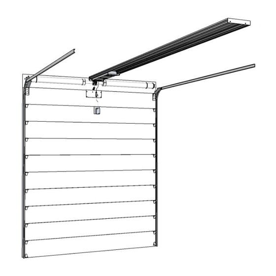
Page 8: Track Installation
DoorLIFT DL-6 Installation guide Remote door system 4. Track installation 4.1 Positioning the rail on the roof Mark the center line on the roof and measure 100mm sideways, as in the picture. BE AWARE: Check pre-installation requirements (page 4) for any reinforcements needed. -
Page 9: Fastening The Rail To The Roof
DoorLIFT DL-6 Installation guide Remote door system 4.2 Fastening the rail to the roof Use the groves in the track to DRILL the required holes. The number of holes depends on the roof structure. Minimum requirements: front, back and middle of the track. -
Page 10: Installing The Door Connector Plate
DoorLIFT DL-6 Installation guide Remote door system 5. Installing the door connector plate IMPORTANT: Page 6 indicated that top panel reinforcements may be required. NOTE: Depending on the shutter structure the installer has to decide on the type of fasteners. -
Page 11: Installing Turnbuckle Connecting Rod
DoorLIFT DL-6 Installation guide Remote door system 6. Installing turnbuckle connecting rod 6.1 Installing the turnbuckle connecting rod Make sure the roll-up door is in the fully closed position. Slide the DoorLIFT motor unit towards the door, as far as it will go, then slide it back from the stop screw approximately 50mm. - Page 12 DoorLIFT DL-6 Installation guide Remote door system Cut the threaded rod to length The length of the threaded rod is: Measurement A - 70 mm NOTE: The operation of the system will be interfered when the rod does protrude into the fork.
-
Page 13: Checking The Turnbuckle Connecting Rod
DoorLIFT DL-6 Installation guide Remote door system 6.2 Checking the turnbuckle connecting rod After installation the connection bar should be in a 30-45 degree angle, when the door is in closed position. The motor-unit should always be 25mm away from the end screw. -
Page 14: Installing The Emergency Release Cable System
DoorLIFT DL-6 Installation guide Remote door system 7. Installing the emergency release cable system 7.1 Drilling the holes Apply the drill template decal and align the left edge of the template with the centerline of the connector plate. Drill the holes completely through as per drill template. -
Page 15: Installing The Release Cable
DoorLIFT DL-6 Installation guide Remote door system 7.3 Installing the release cable Insert the end of the cable with the stop into the guide tube at door-end of the motor unit, push the cable through until you can see it in the opening where the lever is. - Page 16 DoorLIFT DL-6 Installation guide Remote door system Ensure the cable is still 50mm past the release lever in the motor housing and the lever is still engaged. Using good quality cutters cut the cable 25mm below the lock mounting plate. Not...
- Page 17 DoorLIFT DL-6 Installation guide Remote door system Use the two screws provided to secure the exterior cover over the lock assembly. Outside door Locate and secure the rear cable cover on the mounting plate using the two 4,8x32 screws pro- vided.
-
Page 18: Installing The Control Box
DoorLIFT DL-6 Installation guide Remote door system 8. Installing the control box 8.1 Mounting the control box Mount the control box as determined earlier in the manual. Double check the points below to ensure the ideal location. Reminder: the standard battery cable is 2,5m long so the distance from the box to the battery can’t be more than that. -
Page 19: Connect The Cable To The Control Box
DoorLIFT DL-6 Installation guide Remote door system 8.3 Connect the cable to the control box Plug the one end of the profile cable to the box. While connecting, push until you hear a "click". Push in until you hear it “click”... -
Page 20: Optional Functions
DoorLIFT DL-6 Installation guide Remote door system 8.5 Optional functions Connect auxiliary devices to the DoorLIFT control box through the 8 -lead auxiliary harness using the wire chart below as a guide. The pig-tailed end of the harness has numbers. -
Page 21: Connect To The Battery
DoorLIFT DL-6 Installation guide Remote door system 8.6 Connecting to the battery On the pig-tailed end of the DoorLIFT battery cable, splice red wires , and one end of the fuse wire together. A sol- der splice with heat shrink is recommended. Crimp a terminal to the other end of the fuse wire. This will be atta- ched to the positive battery terminal. -
Page 22: Adjusting The Sensors
DoorLIFT DL-6 Installation guide Remote door system 9. Adjusting the sensors 9.1 Adjusting the door closed sensor Remove the rear cover from the track. Remove the plastic cover on the side of the track... - Page 23 DoorLIFT DL-6 Installation guide Remote door system Check the door closed sensor and if necessary set it in the proper place, by closing the door with connected motor unit manually. Set the sensor switch (A) sideways to match the cable slider magnet (B). Both screw heads should be in line, see pic- ture.
-
Page 24: Adjusting The Door Open Sensor
DoorLIFT DL-6 Installation guide Remote door system 9.2 Adjusting the door open sensor The sensor switch for the OPEN position WILL need to be set. Follow the same process as the close sensor switch, mark the track and slide the sensor switch to the desired location. -
Page 25: Programming Remote Controls
DoorLIFT DL-6 Installation guide Remote door system 10. Programming remote controls Note: If applicable 1. When the power is turned on by connecting the battery cable to the control box, within 5 seconds, press buttons 1 and 2 at the same time. -
Page 26: First Operation Of The System
DoorLIFT DL-6 Installation guide Remote door system 11. First operation of the system THE FIRST ACTIVATION AFTER POWER UP IS ALWAYS OPEN. BEFORE TESTING THE SYSTEM FOR THE FIRST TIME, PARTIALLY OPEN THE DOOR SO THE MOTOR IS APPROXIMATELY IN THE MIDDLE OF THE TRACK. - Page 27 DoorLIFT DL-6 Installation guide Remote door system When you are satisfied with the installation and the system has cycled a few times review the following points: Do the turnbuckle clevises move freely when the door moves from the vertical to the horizontal position? Is the lock nut on the turnbuckle rod tightened against the clevis joint? Is the turnbuckle at an acceptable angle, 30 -45°, with the door fully closed?
-
Page 28: Overview Of Electronic Indicators
DoorLIFT DL-6 Installation guide Remote door system 12. Overview of electronic indicators Control box Remote control LED 1 indicator LED 2 indicator LED indicator After connecting the system to power: When a command is given with a remote control or hardwired, the LED’s will indicate the signal was recei- ved. - Page 29 DoorLIFT DL-6 Installation guide Remote door system...
-
Page 30: Appendix A - Push Buttons (Dl-8000810)
DoorLIFT DL-6 Installation guide Remote door system 13. Appendix A - Push buttons (DL-8000810) Colour Wire Function Brown White Down Green +12V Use the 8-wire auxiliary cable to connect the push buttons to, using the numbered wires as shown in the table above... - Page 31 DoorLIFT DL-6 Installation guide Remote door system...
- Page 32 Actuall Innomotive International BV Energieweg 52, 3771NA, Barneveld, The Netherlands +31 (0)33 7074 889 - www.actuall.eu...
Need help?
Do you have a question about the DoorLIFT DL-6 and is the answer not in the manual?
Questions and answers