Advertisement
Quick Links
Thank you for purchasing a Dellonda product. Manufactured to a high standard, this product will, if used according to these
instructions, and properly maintained, give you years of trouble free performance.
IMPORTANT: PLEASE READ THESE INSTRUCTIONS CAREFULLY. NOTE THE SAFE OPERATIONAL REQUIREMENTS, WARNINGS & CAUTIONS. USE
THE PRODUCT CORRECTLY AND WITH CARE FOR THE PURPOSE FOR WHICH IT IS INTENDED. FAILURE TO DO SO MAY CAUSE DAMAGE AND/OR
PERSONAL INJURY AND WILL INVALIDATE THE WARRANTY. KEEP THESE INSTRUCTIONS SAFE FOR FUTURE USE.
Refer to
Wear safety
instruction
gloves during
manual
assembly
1.
SAFETY
Read the installation, operating and maintenance instructions thoroughly before installing or using this equipment.
9
If there is a smell of gas: shut off the gas to the appliance, extinguish any open flames. If odour continues contact gas supplier.
9
DO NOT store or use petrol or other flammable substances inside the housing of the heater.
8
DO NOT store or use petrol or other flammable liquids or gases in the vicinity of the heater.
8
DO NOT store a gas cylinder that is not connected for use in the vicinity of this or any other appliance.
8
WARNING! DO NOT use indoors. For use outdoors or in amply ventilated areas.
‰
An amply ventilated area is one that has a minimum of 25% of the surface area open, see fig.1.
(The surface area is the sum of the wall surface.)
WARNING! Not intended to be installed in recreational vehicles and/or boats.
‰
WARNING! Improper installation, adjustment, alteration, service or maintenance can cause injury or
‰
property damage.
Installation and repair must be carried out by a qualified person.
9
DO NOT attempt to alter in any way.
8
Wear safety gloves during the assembly process.
9
This product must be installed and the gas cylinder stored in accordance with the local regulations in force.
9
DO NOT obstruct the ventilation holes of the cylinder housing.
8
DO NOT move/transport the appliance when in operation. Shut off the gas cylinder at the regulator before moving.
8
DO NOT move/transport the heater until it has cooled down.
8
Use only the type of gas and the type of cylinder specified by the manufacturer.
9
The LP cylinder used with the patio heater must meet the following size requirements:
Diameter 31.8cm x height 58cm, 15kg maximum capacity.
Protect the product from strong wind to prevent tilting.
9
Only use on level ground, capable of supporting the weight of the heater and the gas cylinder.
9
DO NOT connect the gas cylinder directly to the appliance without a regulator. Use only the type of gas specified in the instructions.
8
The whole gas system (hose, regulator, pilot or burner) should be inspected for leaks or damage before use and at least annually, by a
9
suitably qualified person.
All leak testing should be done with an appropriate gas leak detection/soap solution. Never use an open flame to check for leaks, refer
9
to section 6.2.
DO NOT use the heater until all connections have been leak tested.
8
Turn off the gas immediately if a gas smell is detected. Turn cylinder valve OFF. If the leak is at the hose/regulator connection tighten
9
the connection and perform another leak test. If bubbles continue appearing contact your supplier. If the leak is at the regulator/
cylinder connection disconnect from cylinder, reconnect and perform another leak check. If soap bubbles are still seen, cylinder valve
is defective. Return cylinder to its place of purchase.
Keep the ventilation opening of the cylinder enclosure free and clear of debris.
9
DO NOT paint the radiant screen, control panel or top canopy reflector.
8
Control compartment, burner and circulation air passageways of the heater must be kept clean.
9
Turn off gas whilst not in use.
9
LP regulator/hose assembly must be a protected from accidental damage.
9
Any guard removed for servicing/maintenance must be replaced before operation.
9
Keeps adults and children away from the high temperature surfaces, to avoid burns and ignition of clothing.
9
Children should be carefully supervised when they are in the vicinity of the heater.
9
DO NOT hang clothing or other flammable materials on the heater or place them near the heater.
8
2. INTRODUCTION
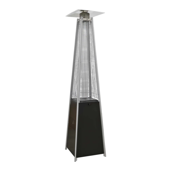
Innovative design of Gas Flame Patio Heater. Contemporary free standing patio heater ideal for both commercial and domestic settings
including open workshops, boat yards, patios, forecourts, gardens and terraces. Standing at 2.2m tall, when lit the heater produces a real
flame encompassed by a glass tube and heats the surrounding area. Metal reflector makes sure the heat is directed downwards and outwards.
Variable heat output controls make it fully adjustable. Features a fully enclosed gas cylinder chamber and safety tip over switch.
PROPANE GAS PYRAMID PATIO HEATERS 13KW
DG5, DG6
MODEL NO:
Original Language Version
fig.1
DG5, DG6 Issue:6 (3,4,5) 30/06/2021
Advertisement

Related Manuals for dellonda DG5


Summary of Contents for dellonda DG5
- Page 1 DG5, DG6 MODEL NO: Thank you for purchasing a Dellonda product. Manufactured to a high standard, this product will, if used according to these instructions, and properly maintained, give you years of trouble free performance. IMPORTANT: PLEASE READ THESE INSTRUCTIONS CAREFULLY. NOTE THE SAFE OPERATIONAL REQUIREMENTS, WARNINGS & CAUTIONS. USE THE PRODUCT CORRECTLY AND WITH CARE FOR THE PURPOSE FOR WHICH IT IS INTENDED.
-
Page 2: Specification
3. SPECIFICATION Max. gas bottle size .......... Ø325 x 700mm Model no’s............. DG5, DG6 Fuel ................Propane Fuel consumption ............945g/hr Heated area ..............8m² Output ................13Kw Dimensions (W x H) ........580 x 2270mm 4. CONTENTS PART DESCRIPTION QTY. Reflector Flame screen Glass tube Upper support Protective guard Black silicone ring Side panel Front panel Gas hose Control box assembly Lower support Block belt Wheel assembly Bottom plate... - Page 3 NOTE: Ensure you leak test this joint as directed in Section 6 after assembly is complete and when you first connect the gas bottle. WARNING! Ensure full engagement of hose to regulator and control ‰ unit. Fig. 4 WARNING! Check that the worm drive clips at both ends of the gas hose ‰ are fully tightened. WARNING! Arrange the gas hose and regulator to ensure the hose does ‰ not come into contact with any high temperature surfaces as it may melt and cause a fire. After the cylinder is placed inside the heater, tightly secure the cylinder with the belt. NOTE: See section 6 for Leak Check procedure. ‰ DG5, DG6 Issue:6 (3,4,5) 30/06/2021 Original Language Version...
- Page 4 Burner Mesh Ensure all components appear as in (Fig. 5) within the control unit, if any components are missing or dislodged. *STOP* Contact the Mixing supplier for assistance. chamber Ignition switch Control Fig. 5 knob DG5, DG6 Issue:6 (3,4,5) 30/06/2021 Original Language Version...
- Page 5 (J) for the door are on the front of the unit, these parts must be on OPPOSITE sides of the unit. This must be correct at this stage to ensure the unit operates correctly. The ignition switch must have a AAA battery inserted into it, Unscrew the collar of the switch and AAA Battery insert a battery then re screw the switch head into place (Fig.6). Fig. 6 Unscrew the button collar until it comes away from the unit. (Fig. 6.1). Fig. 6.1 Slide in a AAA battery and re-screw the button into position. (Fig. 6.2). Fig. 6.2 DG5, DG6 Issue:6 (3,4,5) 30/06/2021 Original Language Version...
- Page 6 5.12. DIAGRAM 3 Assemble the gas cylinder belt. Fix the belt to the two lower supports behind the front door, use 2 x M5 x 12 screws. 5.13. DIAGRAM 4 Assemble the middle support. Insert the 4pcs upper support. Secure with 8 x 3/16” screws. 5.14. DIAGRAM 5 Fix the flame screen to the upper supports. Use 8 x 3/16” screws. DG5, DG6 Issue:6 (3,4,5) 30/06/2021 Original Language Version...
- Page 7 5.15. DIAGRAM 6 Fix the reflector onto the flame screen. Screw the 3 studs onto the top of the flame screen. Place 3x Ø6mm washers on top of the stud. Place the reflector onto the stud and secure with 3 x Ø6mm washers and 3 x wing nuts. 5.16. DIAGRAM 7 Carefully install the glass tube by lifting it up and inserting through the centre hole in the upper plate. Ensure the black silicone ring is attached to the lower edge of the glass tube as illustrated. Slide the glass tube through the hole of the lower plate cover and onto the middle plate. Check and ensure that the glass tube is positioned properly and is completely covering the centre hole of the middle plate. 5.17. DIAGRAM 8 Assemble the protective guard. Fit the protective guards, push the hooks into the slots in the upper supports and let them slide down to secure. Fix the 4 brackets to retain them in place. Original Language Version DG5, DG6 Issue:6 (3,4,5) 30/06/2021...
- Page 8 Section 6 after assembly is complete and when you first connect the gas bottle. Ensure gas hose is fully engaged to stem and the worm drive is fully tightened. WARNING! Ensure full engagement of hose to regulator ‰ and control unit. WARNING! Check that the worm drive clips at both ends ‰ of the gas hose are fully tightened. WARNING! Arrange the gas hose and regulator to ensure ‰ the hose does not come into contact with any high temperature surfaces as it may melt and cause a fire. After the cylinder is placed inside the heater, tightly secure the cylinder with the belt. NOTE: See section 6 for Leak Check procedure. Tap in Off position Original Language Version DG5, DG6 Issue:6 (3,4,5) 30/06/2021...
-
Page 9: Troubleshooting
Pilot will not stay on Debris around pilot Clear dirty area Loose connections Tighten connections Thermocouple bad Replace thermocouple Gas leak in line Check connections Lack of fuel pressure Cylinder nearly empty, refill cylinder Burner will not light Pressure is low Cylinder nearly empty, refill cylinder Opening blocked Remove and clean Control not on Turn valve to on Thermocouple bad Replace thermocouple Pilot light assembly bent Place pilot light properly Not in correct location Position properly and retry DG5, DG6 Issue:6 (3,4,5) 30/06/2021 Original Language Version... - Page 10 WEEE REGULATIONS Dispose of this product at the end of its working life in compliance with the EU Directive on Waste Electrical and Electronic Equipment (WEEE). When the product is no longer required, it must be disposed of in an environmentally protective way. Contact your local solid waste authority for recycling information. ENVIRONMENT PROTECTION Recycle unwanted materials instead of disposing of them as waste. All tools, accessories and packaging should be sorted, taken to a recycling centre and disposed of in a manner which is compatible with the environment. When the product becomes completely unserviceable and requires disposal, drain any fluids (if applicable) into approved containers and dispose of the product and fluids according to local regulations. Note: It is our policy to continually improve products and as such we reserve the right to alter data, specifications and component parts without prior notice. Important: No Liability is accepted for incorrect use of this product. Warranty: Guarantee is 12 months from purchase date, proof of which is required for any claim. Dellonda Ltd., Kempson Way, Suffolk Business Park, Bury St Edmunds, Suffolk. IP32 7AR 01284 757575 support@dellonda.co.uk www.dellonda.co.uk DG5, DG6 Issue:6 (3,4,5) 30/06/2021 Original Language Version...
Need help?
Do you have a question about the DG5 and is the answer not in the manual?
Questions and answers