Table of Contents
Advertisement
Advertisement
Table of Contents

Related Manuals for Siemens FibroLaser III


Summary of Contents for Siemens FibroLaser III
- Page 1 FibroLaser™ III Maintenance and Repair Building Technologies CPS Fire Safety...
- Page 2 Sous réserve de modifications techniques et de la disponibilité. © 2012 Copyright by Siemens Schweiz AG Wir behalten uns alle Rechte an diesem Dokument und an dem in ihm dargestellten Gegenstand vor. Der Empfänger anerkennt diese Rechte und wird dieses Dokument nicht ohne unsere vorgängige schriftliche Ermächtigung ganz oder teilweise Dritten zugänglich machen oder ausserhalb des Zweckes verwenden, zu dem es ihm übergeben worden ist.
-
Page 3: Table Of Contents
About this Document................4 Documentation structure................4 Purpose of the document................4 Qualified personnel ...................4 Warranty and liability.................5 Legal notices .....................5 Safety .......................6 Safety instructions..................6 General safety...................6 Electrical safety ..................7 Laser safety....................7 Application specific safety.................9 Maintenance ..................10 General ....................10 Maintenance work on the controller ............10 3.2.1 The controller ..................10 3.2.2... -
Page 4: About This Document
About this Document About this Document Documentation structure This document is part of the FibroLaser III documentation. The various elements of the technical documentation for FibroLaser III are listed below: System introduction and planning: The document provides an overview of the FibroLaser III system and includes important notes to be adhered to during the project planning. -
Page 5: Warranty And Liability
About this Document Warranty and liability Opening the controller housing and the breaking of an adhesive seal on the housing screws voids any warranty and liability claims! No warranty or liability is accepted for any maintenance and repair work performed on the device, which is not performed by the manufacturer! Fig. -
Page 6: Safety
The controller may only be used as intended by the manufacturer (see the CAUTION! installation manual or the operating manual FibroLaser III). Switch the controller off before connecting or disconnecting any optical fibre sensor cable. Never pull-off an optical fibre connector from an E2000 optical port during an active measurement. -
Page 7: Electrical Safety
Safety Electrical safety Electricity can be a danger to health and life. Immediate medical assistance must be sought following contact with dangerous voltage. WARNING! The controller contains components carrying dangerous voltages. Do not open or repair the controller. Do not operate a controller with damaged housing. - Page 8 Safety Additionally, sufficient measures must be taken to protect against inadvertent reactivation. A warning sign must be placed close to the mains switch of the controller. DANGER DANGER DO NOT DO NOT OPERATE OPERATE WORKING ON EQUIPMENT WORKING ON EQUIPMENT REASON: Name: Date:...
-
Page 9: Application Specific Safety
Safety Application specific safety During the commissioning and testing of the FibroLaser III it must be ensured that: erroneous triggering of transmission devices is prevented in a reliable manner, the fire brigade is informed before test triggering of transmission devices, ... -
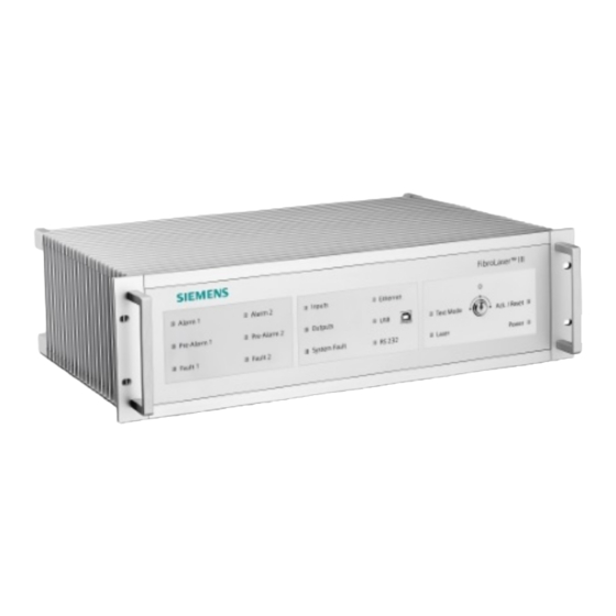
Page 10: Maintenance
Maintenance work on the controller 3.2.1 The controller Fig. 3 Front view of the FibroLaser III controller Fig. 4 Rear view of the FibroLaser III controller Building Technologies FL-III Maintenance and Repair CPS Fire Safety... - Page 11 This LED is controlled by the digital system. It is therefore time-delayed to the POWER ON LED on the rear panel by a few seconds. LED’s on the front side of the FibroLaser III controller Tab. 1 Building Technologies FL-III Maintenance and Repair CPS Fire Safety 08.2012...
- Page 12 Optical ports LASER ON Green Laser operation is enabled. Power supply POWER ON Green Power supply is operating. LED’s on the rear side of the FibroLaser III controller Tab. 2 Incident Mode Duration (Sequence) Power on Long single beep Few seconds.
-
Page 13: Regular Maintenance Work
Maintenance 3.2.2 Regular maintenance work The following work must be performed in connection with regular maintenance: Switch the key switch on the controller to the position “Test Mode” all LED displays on the front panel of the device will light up for a few seconds (LED test). -
Page 14: Maintenance Work On The Sensor Cable
Maintenance Maintenance work on the sensor cable In principle, the sensor cable does not require any maintenance. However, during an annual inspection it is useful to perform a visual inspection of the sensor cables, the connection cables and the connectors with regard to visible damage such as breaks, indentations, strong kinks or bend radii that are too small. -
Page 15: Cleaning The Fibre-Optical Connectors
Maintenance Recommendations: Cleaning cloth Lint-free and suitable for the cleaning of optical components in accordance with the specifications, such as: - KIMTECH Science KIMWIPE® EX-L - Chemtronics OpticWipes - Newport Optics Cleaning Tissue Solvents Ethanol or isopropanol in accordance with the specifications for the use in UV spectroscopy or in a similar ultra-pure quality (>99.9%), such as: - Merck Uvasol®... - Page 16 Maintenance Visual inspection of the fibre-optical connectors Inspect the endfaces of the fibre-optical connectors with a microscope suitable for fibre-optical connectors with a magnification in the range of at least 100x up to a maximum value of 200x. A service adapter E2000 should be used for the easy opening of the protective flap of a fibre-optical connector.
-
Page 17: Cleaning The Internal Fibre-Optical Connectors
Maintenance Cleaning the fibre-optical connectors In order to clean the contaminated endface of a fibre-optical connector, the protective flap of the connector must be opened carefully. Use a service adapter E2000 to open the protective flap. Lightly moisten a suitable lint-free cleaning cloth with an ultra-pure solvent. Carefully wipe the surface with the moist cleaning cloth. - Page 18 Maintenance Fig. 10 Use of the ferrule cleaner (example) In practice, the use of a ferrule cleaner provides good results. In the case of an incomplete cleaning, this process should be repeated several times. Alternatively, the cleaning with a cleaning cloth is possible following the partial pulling out of the optical ports panel (see Chapter “Cleaning the internal fibre- optical connectors with a cleaning cloth”).
- Page 19 Maintenance Location of the assembly groups: (For illustrative purposes, a sectional view of the housing cover is used.) The following images show the the location of the mating adapter(s) and the fibre- optical connector(s) of the controller. Fig. 11 Mating adapter of the fibre-optical connectors (left), dummy connector and internal fibre-optical connector (right) Fig.
- Page 20 Maintenance Procedure: Switch the controller off and disconnect the power supply cable before partially pulling out the optical ports panel Loosen the four screws of the optical ports panel, so that these protrude at least 1 cm (see figure 13). Partially pull out the optical ports panel holding the optical ports from the housing.
-
Page 21: Fault Diagnostics
Fault Diagnostics Fault Diagnostics Hardware Based on the fault indication, the possible causes and their corrective actions can be worked through successively. If the respective item is correct and the fault indication is still present, then continue with the next item. 4.1.1 The controller does not show a response, no LED is lit Observations:... - Page 22 Fault Diagnostics The fuse has been blown Switch off the controller, disconnect the power supply cable. Check the fuse with a multi-meter or continuity tester and replace it if necessary. Power supply, 12V to 48V DC: Fuse: 4 A (T), 5 x 20 mm –...
-
Page 23: The Controller Does Not Show A Response, Led "Power On" Is Lit
Fault Diagnostics The power supply is faulty or there is a defect in one of the modules that are to be supplied Check the power supply separated from the modules that are to be supplied: Disconnect the power supply cable (disconnect the device from the mains –... -
Page 24: The Controller Does Not Start The Measurement
Fault Diagnostics 4.1.3 The controller does not start the measurement Observations: When the controller is switched on: the LED “Power” on the front panel of the device and the LED “Power On” on the rear panel of the device are lit. The LED’s light up for approx. -
Page 25: Errors
Fault Diagnostics 4.2.2 Errors System Name address Description Troubleshooting point System fault Triggered by any Check further error messages to analyse the controller fault, fibre issue. break, measurement stopped or power off. Configuration error Configuration is not Repeat commissioning with reduced number of loaded by the controller. -
Page 26: Warnings
Fault Diagnostics 4.2.3 Warnings System Name Description Troubleshooting address point Configuration Configuration data is not valid. Repeat the commissioning warning procedure. Send the support information to the technical support department, if required. Measurement Single invalid measurement. This Check the environmental conditions warning measurement is ignored, and as well as the sensor cable and / or... -
Page 27: Repairs
Repairs Repairs General The event memory, the status report and the support information of the controller must be read out with the FibroManager BEFORE and AFTER the work and must be stored for documentary purposes. In the case of a repair, in addition to the repair report, the data from the event memory, the status report and the support information must also be sent to the technical support department of the manufacturer. -
Page 28: Repairs On The Closed Controller
Repairs Repairs on the closed controller 5.2.1 Replacement of the fuse If no LED’s light up on the front or rear after switching on the controller, no buzzer is audible and no connection can be established with the software FibroManager, it is possible that the fuse has been triggered. -
Page 29: Replacement Of The Memory Card
Repairs Fuse replacement of the 100 to 240V AC power supply Fig. 15 Fuse replacement with the 100 to 240V AC power supply Remove the power supply cable. To replace the fuse, carefully lever out the fuse drawer with a suitable tool (screwdriver, 4 mm flat head). - Page 30 Repairs Evaluation of the data The data and the defective CF memory card should be submitted respectively returned to the manufacturer of the controller for evaluation. Within the warranty period, the replaced memory card must be returned to the manufacturer in order to maintain the warranty.
-
Page 31: Repairs On The Open Controller
Repairs Fig. 18 Reinstall the cover of the CF memory card slot The newly inserted memory card is automatically recognised after switching on the controller and if necessary automatically be initialised. Only high-quality CF memory cards, which meet the specifications indicated above (recommendation: industry standard), should be installed. - Page 32 Repairs Fig. 19 Anti-static mat / ESD protective measures (diagram illustrating the principle) Recommendation: Item Supplier Order number Anti-static service kit - ESD mat with earthing connection - Black cable with earthing point www.farnell.com 877-682 - Alligator clip - Yellow spiral cable - ESD wrist strap Electrostatic energy can cause irreparable damage to the device.
- Page 33 Repairs Opening the controller housing The following indicated screws must be loosened and removed in order to open the controller housing. Subsequently, the housing cover can be removed. Store the screws together at a safe location. The mounting of the housing cover is performed in the reverse order. ...
-
Page 34: Battery Replacement
Repairs Location of the modules in the controller Fig. 21 Location of the modules in the controller for maintenance and repair work Power supply side wall Internal AC/DC voltage converter Power supply panel Power supply Interface panel (variant depending on the expansion with interface cards) ... - Page 35 Repairs The capacity of the battery is automatically monitored by the digitalboard of the controller. When the battery voltage drops below the required level, a warning is generated in due time and it is recorded in the event memory of the controller. The controller is also functional without a battery.
-
Page 36: Power Supply Replacement
Repairs After the work is completed, it is necessary to perform a functional test and commissioning of the controller. Particularly a “Quick Start” and “Scan” of all channels with the FibroManager must be performed in order to set the status of the controller and the status of the fibre(s). - Page 37 Repairs Device version with 12V to 48V DC power supply Fig. 23 Location of the power supply In order to replace the power supply, the housing of the controller must be opened. Release and remove the housing cover of the controller. Fully remove the single mounting screw of the fitting panel of the power supply from the floor of the housing (fig.
- Page 38 Repairs Fig. 24 Location of the mounting screws of the power supply and of the connector to the mainboard (12V to 48V DC power supply) Device version with 100V to 240V AC power supply In the case of the device version with 100V to 240V AC power supply, the internal AC/DC voltage converter, the power supply or both modules are to be replaced.
- Page 39 Repairs Replacement of the internal AC/DC voltage converter Fig. 25 Location of the internal AC/DC voltage converter The housing cover as well as the housing side wall facing the power supply must be disassembled for the removal of the power supply respectively the internal AC/DC voltage converter.
- Page 40 Repairs Fig. 27 Laid down housing side wall with internal AC/DC voltage converter Fig. 28 Removal of the internal AC/DC voltage converter from the housing side wall (left) and from the intermediate panel (right) Fig. 29 Assignment of the connectors of the internal AC/DC voltage converter Release and remove the housing cover of the controller.
- Page 41 Repairs Remove the intermediate panel with the internal AC/DC voltage converter from the housing side wall (fig. 28 left). Remove the internal AC/DC voltage converter from the intermediate panel (fig. 28 right). Remove the colour-coded leads from the screw terminals of the internal AC/DC voltage converter.
-
Page 42: Interface Cards Replacement Or Expansion
Repairs Fig. 30 Location of the mounting screws of the power supply and of the connector to the mainboard (100V to 240V AC power supply) 5.3.4 Interface cards replacement or expansion A distinction is made during the installation of interface cards (12-way input card / 12-way output card or 24-way output card) between the replacement of faulty interface cards as well as the expansion of the controller with additional interface cards. - Page 43 Repairs Installation / replacement of the riser card The riser card provides four slots for the installation of interface cards. The slots of the riser card are numbered from the lowest slot (Slot 1) to the highest slot (Slot 4). Fig.
- Page 44 Repairs Fig. 33 Locking for the fixation of the riser card After completion of the work, a functional test and commissioning of the controller is required. After installation or replacement of a riser card and additional WARNING! interface cards, ALL inputs and outputs must be tested. Replacement of the interface panel Disassembly Remove the three screws of the interface panel on the housing floor.
- Page 45 Repairs Assembly In the case of an optional interface panel, the unused cut-outs for interface cards must be closed off with blind covers. Together with the basic kit for the expansion of the inputs / outputs these blind covers are mounted to the supplied optional interface panel and must be removed depending on the expansion configuration.
- Page 46 Repairs Replacing a defective interface card Procedure: Release and remove the housing cover of the controller. Disassemble the interface panel. Pull off the defective interface card from the respective slot of the riser card. Insert the new interface card in the respective slot of the riser card. Mount the interface panel.
- Page 47 Repairs Comb. Slot 4 Slot 3 Slot 2 Slot 1 ∑In ∑Out Possible combinations of the assignment of the slots with: Tab. 9 - 24-way output cards (O) or - 12-way input cards / 12-way output cards (I/O) The modified configuration of interface cards is automatically recognised by the controller.
- Page 48 Repairs After completion of the work, a functional test and commissioning of the controller is required. Follow the instructions for the required sequence / positioning during the installation of the interface cards. ALL inputs and outputs must be tested after the additional installation of an interface card or the relocation of an interface WARNING! card that had already been present.
- Page 49 Repairs Preparation: Connect the I/O Tester to the connector of the respective inputs or outputs that are to be tested. Connect the cable “4x Input” to the Sub-D9 socket “Input” for external power supply of the I/O Tester. Configure the controller: set up at least one zone in a measurement channel. Additionally, activate the entry “Deactivate programmable outputs”...
-
Page 50: Repair Of Sensor Cables
Repairs Repair of sensor cables In case of any damage to a sensor cable, switch off the WARNING! controller(s) connected to the cable as soon as possible. Cut out the damaged sensor cable section and replace it with a new cable length. Use two splice boxes for this. -
Page 51: Accessories And Spare Parts
Accessories and Spare Parts Accessories and Spare Parts OTS-30xx Expansion modules Article no. Description 53654001 Basic set for the expansion of the inputs / outputs (riser card + optional interface panel). Note: This item must be ordered controller-specific due to the specific nameplate with the corresponding serial number and the device model. - Page 52 Repair Report OTS30xx Repair report Date Contractor performing the work Service technician performing the work Client Project name Controller name Controller serial number (S/N) Controller model Description of the issue: Countermeasures implemented (general description): Performed work: Replacement of memory card Installation / replacement of riser card and interface panel Installation / replacement of 24-way output card Installation / replacement of 12-way input card / 12-way output card...
- Page 53 Repair Report Building Technologies FL-III Maintenance and Repair CPS Fire Safety 08.2012...
- Page 54 Siemens Schweiz AG Sector Infrastructures & Cities Building Technologies Division International Headquarters CPS Fire Safety Gubelstrasse 22 CH-6301 Zug Tel. +41 41 724 24 24 www.siemens.com/buildingtechnologies Document no. A6V10335143_a_en_-- Operating Manual FibroLaser Issue 08.2012 Register 2...
Need help?
Do you have a question about the FibroLaser III and is the answer not in the manual?
Questions and answers