
Related Manuals for ClimateWorx IR Series


Summary of Contents for ClimateWorx IR Series
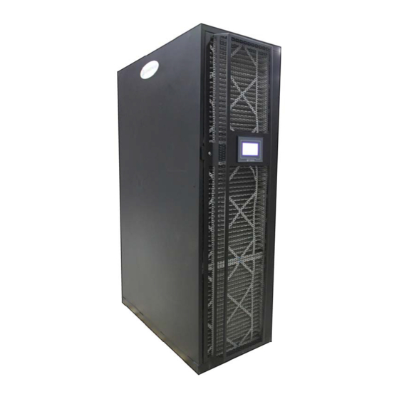
- Page 1 In Row Installation Manual ClimateWorx International Inc. 14 Chelsea Lane, Brampton, Ontario, Canada L6T 3Y4...
- Page 2 In Row Installation Manual - 2 - In Row-M52-IM2017.doc...
-
Page 3: Table Of Contents
In Row Installation Manual Table of Contents: 1.0 Site Preparation ............... 4 2.0 Location Consideration ............. 5 Positioning of Indoor Units ....................5 Positioning of Outdoor Heat Rejection Devices ..............6 3.0 Installation .................. 7 3.1 Handling and Unpacking Equipment ................7 3.2 Electrical Connection .................... -
Page 4: Site Preparation
In Row Installation Manual 1.0 Site Preparation In order to maximize operation efficiency and performance, the following areas should be observed in the site planning stage: A vapor seal to eliminate moisture migration through the building structure should surround the room. Windows should be sealed and at least double-glazed to prevent sweating. -
Page 5: Location Consideration
The units are designed to be free standing on a slab floor or a raised floor with sufficient supports underneath. The unit should be isolated using a suitable isolation method. ClimateWorx OEM equipment uses a threaded leveling foot with a locking nut. Use bottom nut to lock the leveling foot in place. -
Page 6: Positioning Of Outdoor Heat Rejection Devices
In Row Installation Manual Positioning of Outdoor Heat Rejection Devices The outdoor heat rejection devices such as air-cooled condensers and glycol coolers should be located as close to the indoor unit as possible. From a security and environment standpoint, the outdoor heat rejection devices should be installed away from public access and occupied spaces where low ambient sound level is required. -
Page 7: Installation
3.0 Installation 3.1 Handling and Unpacking Equipment 3.1.1 Initial Inspection Upon arrival of the ClimateWorx unit and prior to unpacking it, please conduct a visual inspection of the unit. Check for external damage(s) whether visible or concealed. Any damage(s) noted should be immediately reported to the transport carrier. - Page 8 In Row Installation Manual 3.1.3 Removing Unit from Skid: 1. Use a forklift to physically remove unit from skid. 2. Align the forklift with either the front or rear side of the unit. Y E S 3. Make sure forklift forks are full into unit – do not lift unit if forks are halfway in –...
-
Page 9: Electrical Connection
In Row Installation Manual 3.2 Electrical Connection All models are fitted with one (two when ATS is provided), 3-pole mains isolators, neutral and earth terminal, which are located in the electrical power panel. The isolators and terminals will accept cables up to #2 AWG (35 mm²). -
Page 10: Auto Transfer Switch (Optional On 24")
In Row Installation Manual 4.0 Auto Transfer Switch (Optional on 24”) 4.1 ATS Principle of Operation ClimateWorx Electrical Panel c/w A T S Components and power source selector switch The Auto Transfer Switch monitors the availability of power from either source to the... -
Page 11: Ats Features
In Row Installation Manual 4.2 ATS Features The Auto Transfer Switch, (ATS) feature of the ClimateWorx unit must be powered from two separate independent sources to function properly. There are two non-fused disconnect switches in the unit, one for the primary power source A and one for primary power source B. -
Page 12: Refrigerant Pipe Work Installation
In Row Installation Manual Refrigerant Pipe work Installation Good practices should always be followed when connecting refrigerant piping in systems. As many of the operational problems encountered in a refrigeration system can be traced back to improper design and installation of refrigerant piping, it is essential that the following guidelines be observed: 1. -
Page 13: Recommended Pipe Size For Remote Condenser
In Row Installation Manual discharge lines increases the initial cost of the project and can reduce the refrigerant gas velocity to a level where oil is not returned to the compressor.Recommended pipe sizes are tabulated as follows: Recommended Pipe Size for Remote Condenser Model 12”... - Page 14 In Row Installation Manual 6. Release all pressure. Connect a vacuum pump to the compressor suction and discharge valves with refrigerant or high vacuum hoses. Provide an isolating valve and a pressure gauge for pressure checking. 7. Evacuate the system to an absolute pressure not exceeding 500 microns. Break the vacuum to 2psig with dry nitrogen.
-
Page 15: Charging
In Row Installation Manual Charging Proper performance of the system depends largely on proper charging. Adhere to the following guidelines for charging: Calculate the total charge required using this formula: Indoor Unit Charge + Liquid Line Charge + Condenser Charge + Hot gas Line Charge + 20% of Receiver volume = Total Charge When head pressure control is utilized, there must be enough refrigerant to flood the condenser at the lowest expected ambient and still have enough charge in the system for... -
Page 16: Water / Glycol / Chilled-Water Pipe Work Installation
In Row Installation Manual Water / Glycol / Chilled-water Pipe work Installation The Water / Glycol / Chilled-water pipe work in all systems should be installed in accordance with the following recommendations: 1. A manual shut-off valve should be installed at the supply and return pipes of each indoor unit for routine service and emergency isolation of the unit. - Page 17 In Row Installation Manual 7. Concentration of glycol required depends on the minimum ambient temperature. The following glycol concentration is recommended: % of Ethylene Glycol by Weight Minimum Operating Temp °C (°F) 0 (32) - 5 (23) -11.6 (11) - 20 (-4) - 32.2 (-26) - 17 -...
-
Page 18: Piping Connection Sizes
In Row Installation Manual Piping Connection Sizes Model 12” 24” Steam Condensate –ODM 3/4” 3/4” Humidifier Water –ODM 1/4” 1/4” Cooling Coil Condensate –ODM 3/4” 3/4” Chilled Water –ODM 1 1/8” 1 3/8” Condensing Water –ODM 7/8” 1 1/8” Glycol Solution –ODM 7/8”... -
Page 19: Temperature (Rack) Sensor Installation
In Row Installation Manual Temperature (Rack) Sensor Installation 1. Route the sensor through either the top or the bottom of the equipment 2. Secure the temperature sensor in front of the warmest heat source in the enclosure. Do not secure in front of a blanking panel 3. -
Page 20: Appendix A: Dimensional Drawings
In Row Installation Manual Appendix A: Dimensional Drawings Drawing Title Drawing No. SERIES IR – Dimensional Drawing 12” IRC-12-SUBMITTAL-A SERIES IR – Dimensional Drawing 24” IRC-24-SUBMITTAL-A - 20 -... - Page 21 In Row Installation Manual - 21 -...
- Page 22 In Row Installation Manual - 22 -...
-
Page 23: Appendix B: Piping Schematic Diagrams
In Row Installation Manual Appendix B: Piping Schematic Diagrams Drawing Title Drawing No. SERIES IR – Chilled Water System Schematic IRDS401 SERIES IR – Air Cooled System Schematic IRDS101 SERIES IR – Water Cooled System Schematic IRDS201 - 23 -... - Page 24 In Row Installation Manual - 24 -...
- Page 25 In Row Installation Manual - 25 -...
- Page 26 In Row Installation Manual - 26 -...
-
Page 27: Appendix C: Electrical Schematic Diagrams
In Row Installation Manual Appendix C: Electrical Schematic Diagrams Drawing Title Drawing no. Electric Schematic Air-Cooled – General, ES9030 Electric Schematic Water/ Glycol-Cooled – General, ES9065 Electric Schematic Chilled Water – General, ES9050 Electric Schematic – Field Wiring Standby Start/ M52ES05 Standby Enable, For automatic change over Electric Schematic –... - Page 28 In Row Installation Manual - 28 -...
- Page 29 In Row Installation Manual - 29 -...
- Page 30 In Row Installation Manual - 30 -...
- Page 31 In Row Installation Manual - 31 -...
- Page 32 In Row Installation Manual - 32 -...
- Page 33 In Row Installation Manual - 33 -...
- Page 34 In Row Installation Manual - 34 -...
Need help?
Do you have a question about the IR Series and is the answer not in the manual?
Questions and answers