Table of Contents
Advertisement
Quick Links
2202G1JE-DA-M-N_2010.01.
Third Edition 2010/1/5
Reciprocating Compressor
M Series Operation Manual
4M/6M/8M/62M/62M-FM
CAUTION
Before operating, inspecting, or servicing the compressor, read this manual thoroughly to fully
understand the contents.
Keep this operation manual in a safe, designated place for future reference whenever the
manual is needed.
3–14–15 Botan Koto-ku, Tokyo 135-8482, Japan
Advertisement
Table of Contents
Troubleshooting

Related Manuals for MAYEKAWA M Series


Summary of Contents for MAYEKAWA M Series
- Page 1 2202G1JE-DA-M-N_2010.01. Third Edition 2010/1/5 Reciprocating Compressor M Series Operation Manual 4M/6M/8M/62M/62M-FM CAUTION Before operating, inspecting, or servicing the compressor, read this manual thoroughly to fully understand the contents. Keep this operation manual in a safe, designated place for future reference whenever the manual is needed.
- Page 3 2202G1JE-DA-M-N_2010.01. Preface Preface Thank you for having purchased our M series reciprocating compressor (hereinafter indicated as "this machine"). This operation manual (hereinafter indicated as "this manual") describes safety information, operational and maintenance procedures in detail for safe and effective use of this product.
- Page 4 If malfunctions or damages occur under proper usage (conditions) following documents such as operation manual or drawings of this product, or, if MAYEKAWA judges that malfunctions or damages are related to design or manufacture of the product, and if the malfunctions or damages are within the warranty period, we will repair or replace the product without any charges.
- Page 5 Important Information for Safe Use of the Product Although MAYEKAWA has paid a lot of attention to safety measures for this product, all hazards including potential hazards caused by human errors, or due to environmental conditions can not be anticipated.
- Page 6 This manual is copyrighted. Drawings and technical references including this manual shall not, in whole or part, be copied, photocopied, or reproduced into any electronic medium or machine-readable form without prior permission from MAYEKAWA. Photographs or drawings included in this manual may differ from the appearance of actual product.
- Page 7 TEL: (1) 305-477-5741 INDUSTRIAL REFRIGERATION MIAMI, FL 33166, U.S.A. FAX: (1) 305-477-5681 DIVISION (MIAMI OFFICE) MAYEKAWA U.S.A. INC. 15905 BROOKWAY DRIVE UNIT 4208 TEL: (1) 704-896-3632 INDUSTRIAL REFRIGERATION HUNTERSVILLE, NC 28078, U.S.A. FAX: (1) 704-896-3697 DIVISION (CHARLOTTE OFFICE) Reciprocating Compressor M Series...
- Page 8 TEL: (91) 12-4420-6616 INDIA PVT.LTD. GOLF COURESE ROAD, SECTOR 53, FAX: (91) 12-4420-6618 GURAGAON, HARYANA, 122002, REPBLIV OF INDIA MAYEKAWA AUSTRALIA UNIT 2, 44 MCCAULEY STREET TEL: (61) 2-9695-7000 PTY.LTD. MATRAVILLE NSW 2036, AUSTRALIA FAX: (61) 2-9695-7001 Reciprocating Compressor M Series...
- Page 9 SAMUTPRAKARN 10540, THAILAND MAYEKAWA MFG.CO., LTD. ROOM 305, 3FL, TOUI TRE TOWER, TEL: (84) 8-3997-5284 HO CHI MINH CITY 60A HOANG VAN THU, WARD 9, FAX: (84) 8-3997-5287 REPRESENTATIVE OFFICE PHU NHUAN DIST., HO CHI MINH CITY, VIETNAM Reciprocating Compressor M Series...
- Page 10 FAX: — GRANDE-MS, CEP 79010-190, BRASIL MAYEKAWA DO BRASIL LTDA. RUA C, 255 – QUADRA 588 – LOTE 4/8 SALA TEL: (55) 62-3093-5062 (GOIANIA BRANCH) 1004 – CENTRO EMPRESARIAL SEBBA FAX: — GOIANIA-GO, CEP 74280-010, BRASIL Reciprocating Compressor M Series viii...
- Page 11 S.A. DE C.V. COL.DEPORTIVA, C.P.36612, IRAPUATO, GTO. FAX: (52) 462-624-9264 (IRAPUATO OFFICE) MEXICO MAYEKAWA DE MEXICO, AV. NICOLAS BRAVO 1572, LOCAL 1 TEL: (52) 66-7715-4199 S.A. DE C.V. COL.MORELOS CULIACAN, SINALOA, FAX: (52) 66-7715-4150 (CULIACAN OFFICE) C.P.80170, MEXICO Reciprocating Compressor M Series...
- Page 12 2.2.1 Specification/ 2.3 Selection of V-belt/7.1 Yamamoto, Yamada Development View and Configuration Table of the Parts - Parts Configuration Table/7.7 Parts Inspection and Replacement Standards - “O”ring List 2010/1/5 Parts drawing change due to design change, addition of Yamamoto, Yamada 62M/62M-FM Reciprocating Compressor M Series...
-
Page 13: Table Of Contents
2.1.2 Cross-Sectional View of Assembly................ 2-3 2.1.3 Oil Supply Mechanism ................... 2-5 2.1.4 Unloader Mechanism..................... 2-6 Specification of Compressor ..............2-7 2.2.1 Specification......................2-7 2.2.2 Service Limits and Range..................2-8 2.2.3 External Dimensions....................2-9 Selection of V-belt..................2-12 Reciprocating Compressor M Series... - Page 14 4.4.3 Operation after the Compressor has been stopped for Long Period of Time ..4-7 Maintenance Safety Precautions for Maintenance ............5-1 Periodic Inspection ..................5-2 5.2.1 Daily Inspection ..................... 5-2 5.2.2 Monthly Inspection....................5-3 5.2.3 Biannual Inspection ....................5-3 Reciprocating Compressor M Series...
- Page 15 5.5.5 Unloader ......................5-29 5.5.5.1 Attentions for Attaching the Unloader Push Rod Washer......5-30 5.5.5.2 Attentions for Attaching the Unloader Push Rod Assembly ...... 5-30 5.5.5.3 Attentions for Attaching the Solenoid Valve Unloader Cover Integrated ... 5-31 Reciprocating Compressor M Series xiii...
- Page 16 5.5.14.2 Attentions for Attaching the Thrust Washer (Pump Side)......5-50 5.5.15 Oil Filter Assembly....................5-51 Troubleshooting Troubleshooting Table ................6-1 Related Document Development View and Configuration Table of the Parts ......7-1 List of Tightening Torques for Bolts and Nuts........7-12 List of Tools for Disassembly ..............7-13 Reciprocating Compressor M Series...
- Page 17 Table of Contents Vibration and Sound Data .................7-15 7.4.1 Vibration....................... 7-15 7.4.2 Sound Data ......................7-16 Oil Cooler Heat Rejection (OHR)/ Head Jacket Heat Rejection (JHR) (N4M, N6M, N8M) ......7-17 Starting Torque ..................7-27 Parts Inspection and Replacement Standards........7-31 Reciprocating Compressor M Series...
- Page 18 2202G1JE-DA-M-N_2010.01. Table of Contents Reciprocating Compressor M Series...
-
Page 19: Safety
The worker himself must always lock out/tag out the compressor before working in the compressor for troubleshooting during operation, setup, cleaning, or maintenance and inspection of the compressor. The worker who performed lockout/tagout should release them after checking that all procedures have completed. Reciprocating Compressor M Series 1.1 Observation/Prevention... -
Page 20: Do's About Personal Protective Devices
Do not touch, clean, or lubricate any moving part of the compressor during operation. Do not touch, clean, or lubricate the compressor during its operation. Do not touch relays or electric systems such as terminal block with bare hands when turning on the power. Reciprocating Compressor M Series 1.1 Observation/Prevention... -
Page 21: Warnings
Indicates a potential hazardous situation which, if not avoided, may result in minor or moderate injury. Indicates a potentially hazardous situation which, if not avoided, may result in property damage. Emphasizes important items and indicates profitable information. Reciprocating Compressor M Series 1.2 Warnings... -
Page 22: Safety Labels
Inform our service center of the product name and safety label No when placing a purchase order for safety labels. Types of Safety Labels Table 1-1 Safety label Safety labels Remarks For specification with belt cover Reciprocating Compressor M Series 1.2 Warnings... - Page 23 The figure below shows the affixing positions of safety labels. The numbers in the figure correspond to the ones in Table 1-1 Safety label. Fig. 1-1 Affixing positions of safety labels (Ex: 6M) Fig. 1-2 Affixing positions of safety labels (Ex: 62M-FM Reciprocating Compressor M Series 1.2 Warnings...
-
Page 24: Remaining Hazard
Damage caused by high Wearing protective Lockout/tagout of motor K Motor temperature devices main power and control Electric Shock power Wearing protective devices Operation with a temperature of 40°C or less Reciprocating Compressor M Series 1.3 Remaining Hazard... - Page 25 2202G1JE-DA-M-N_2010.01. 1 Safety Fig. 1-3 Hazardous sources (Ex: 6M) Fig. 1-4 Hazardous sources (Ex: 62M-FM) Reciprocating Compressor M Series 1.3 Remaining Hazard...
-
Page 26: Safety Devices
Methods of Performing and Releasing Lockout/Tagout Make sure to clearly notify methods of performing and releasing lockout/tagout referring to the regulations created by Occupational Safety & Health Administration (OSHA) or local governing body. Reciprocating Compressor M Series 1.4 Safety Devices... -
Page 27: Safety Belt/Coupling Guard
Driving section safety cover (for belt) Driving section safety cover (for coupling) Inspection Method/Cycle Specify the inspection methods/cycle of the safety cover, and make sure to provide users of this compressor with them. Reciprocating Compressor M Series 1.4 Safety Devices... -
Page 28: Safety Valve
Set the pressure of safety valve to the designed system pressure or lower. Specify the safety valve settings, and make sure to provide users of this compressor with them. Inspection Method/Cycle Insure to replace or repair safety relief valve following the local, state, federal acts and regulations. Reciprocating Compressor M Series 1.4 Safety Devices 1-10... -
Page 29: Automatic Control And Protection Equipment M Compressor
It automatically controls opening/closing of the solenoid valve connected to the unloader piston in the capacity control mechanism of compressor. Reciprocating Compressor M Series 1.4 Safety Devices 1-11... - Page 30 (HP)/low pressure control equipment (LP) Description Description Low pressure gauge connection φ 6 (LP/OP) Oil pressure gauge connection φ 6 (OP) High pressure gauge connection φ6 (HP) Intermediate pressure gauge connection φ 6 (OP) Reciprocating Compressor M Series 1.4 Safety Devices 1-12...
- Page 31 If low oil pressure failure protection (OP) or high pressure protection (HP) shutdown the system, make sure to eliminate the cause of it before resetting the compressor. Reciprocating Compressor M Series 1.4 Safety Devices 1-13...
-
Page 32: Compressor Cooling Fluid Temperature Failure Alarm
The thermometer switch requires set up and testing before operating the compressor and periodically after that. Specify the inspection methods/cycle of the thermometer switch, and make sure to provide users of this compressor with them. Reciprocating Compressor M Series 1.4 Safety Devices 1-14... -
Page 33: Example Of Material Safety Data Sheet (Msds)
2202G1JE-DA-M-N_2010.01. 1 Safety Example of Material Safety Data Sheet (MSDS) Reciprocating Compressor M Series 1.5 Example of Material Safety Data Sheet (MSDS) 1-15... - Page 34 2202G1JE-DA-M-N_2010.01. 1 Safety Reciprocating Compressor M Series 1.5 Example of Material Safety Data Sheet (MSDS) 1-16...
-
Page 35: Configuration And Specification Of Compressor
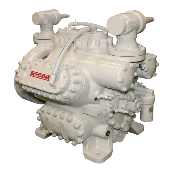
2202G1JE-DA-M-N_2010.01. 2 Configuration and Specification of Compressor Configuration and Specification of Compressor Configuration of Compressor 2.1.1 Overall View of Compressor Fig. 2-1 Overall view (Ex: 6M) Reciprocating Compressor M Series 2.1 Configuration of Compressor... - Page 36 Oil cooler (Optional) 13 Control switch (Control console) (Optional) Oil heater (Optional) 14 Unloader solenoid valve For names of each part, refer to "7.1 Development View and Configuration Table of the Parts". Reciprocating Compressor M Series 2.1 Configuration of Compressor...
-
Page 37: Cross-Sectional View Of Assembly
2202G1JE-DA-M-N_2010.01. 2 Configuration and Specification of Compressor 2.1.2 Cross-Sectional View of Assembly Fig. 2-3 Front view (4M) Fig. 2-4 Side view (4M) Fig. 2-6 Side view (6M) Fig. 2-5 Front view (6M) Reciprocating Compressor M Series 2.1 Configuration of Compressor... - Page 38 2202G1JE-DA-M-N_2010.01. 2 Configuration and Specification of Compressor Fig. 2-7 Front view (8M) Fig. 2-8 Side view (8M) Fig. 2-9 Front view (62M) Fig. 2-10 Side view (62M) Reciprocating Compressor M Series 2.1 Configuration of Compressor...
-
Page 39: Oil Supply Mechanism
When the solenoid valve is energized (ON), refrigerant oil enters the unloader cylinder and presses the unloader piston, and then the unloader mechanism becomes loaded. At this time, the oil flow stops. However, the unloader piston retains the position by being pressurized continuously. Reciprocating Compressor M Series 2.1 Configuration of Compressor... -
Page 40: Unloader Mechanism
The cam ring is moved by oil pressure and the spring. If the unloader piston is not pressurized by oil, it becomes unload by the force of spring. Therefore, the capacity can be controlled by cutting off the oil pressure during machine operation. This is performed by a three-way solenoid valve. Reciprocating Compressor M Series 2.1 Configuration of Compressor... -
Page 41: Specification Of Compressor
For over hang motor specification (140 kW), see the value in parentheses. Table 2-2 Specification of motor Item Unit 75kW 90kW 140kW Rated output Voltage 220 or 440 Frequency 50 or 60 Number of poles – Type – Drip-proof case type (exclusive flange) Reciprocating Compressor M Series 2.2 Specification of Compressor... -
Page 42: Service Limits And Range
For single-stage/double-stage switching operation, see the value in parentheses. This product is designed to be used indoor or on land. Outdoor or shipboard application is possible by option. Contact us for outdoor or shipboard application. Reciprocating Compressor M Series 2.2 Specification of Compressor... -
Page 43: External Dimensions
If the compressor is attached with shut off valve, maximum discharge pressure is 20 kg/cm . The condensed temperature upper limit is 50°C in that case. Fig. 2-13 Service range of M series (NH Table 2-4 Service limits of motor Item Range... - Page 44 2202G1JE-DA-M-N_2010.01. 2 Configuration and Specification of Compressor Fig. 2-15 External dimensions (6M) Fig. 2-16 External dimensions (8M) Fig. 2-17 External dimensions (62M) Reciprocating Compressor M Series 2.2 Specification of Compressor 2-10...
- Page 45 2202G1JE-DA-M-N_2010.01. 2 Configuration and Specification of Compressor Fig. 2-18 External dimensions (62M-FM) Reciprocating Compressor M Series 2.2 Specification of Compressor 2-11...
-
Page 46: Selection Of V-Belt
2202G1JE-DA-M-N_2010.01. 2 Configuration and Specification of Compressor Selection of V-belt 50 Hz 60 Hz Region Number of V-belt Motor Reciprocating Compressor M Series 2.3 Selection of V-belt 2-12... -
Page 47: Installation
Read this chapter and related documents, and fully understand their contents before performing installation. Electrical works should be performed only by electrical engineers. Do not place any part of your body under the lifted compressor. Reciprocating Compressor M Series 3.1 Safety Precautions for Installation... -
Page 48: Installation Works
Lift the compressor slowly. If it is lifted rapidly, it may damage the lifting tools such as wire rope or a part of the compressor. When moving the lifted compressor, always use tag line/induction rope. Do not lift the compressor over head unless absolutely necessary. Do not lower the compressor and block the passage. Reciprocating Compressor M Series 3.2 Installation Works... - Page 49 When lowering the compressor onto two or more blocks, align the tops of blocks so that the compressor becomes stable horizontally on them. Lower the lifted compressor slowly so that it is not damaged by impact on the ground. Reciprocating Compressor M Series 3.2 Installation Works...
-
Page 50: Preparation For Installation
The figures below show the minimum necessary space for disassemble and reassemble of the compressor. Referring to these figures, secure space which allows easy operation, cleaning, maintenance, and inspection. Fig. 3-1 Installation space Reciprocating Compressor M Series 3.2 Installation Works... - Page 51 Oil pressure gauge connection port φ6 Cooling water inlet 20A (Rc3/4) Cooling water outlet 20A (Rc3/4) 20A (Rc3/4) Oil separator return inlet Rc1/2 High stage: Rc3/4 Safety valve connection port Rc3/4 Rc1¼ Low stage: Rc1 Reciprocating Compressor M Series 3.2 Installation Works...
-
Page 52: Installation
For details, refer to "1.4.5 Automatic Control and Protection Equipment of Refrigerating Machine". Low oil pressure failure protection equipment (OP) High pressure protection equipment (HP) Low pressure control equipment (LP) Reciprocating Compressor M Series 3.2 Installation Works... -
Page 53: Centering Of The Compressor/Driving Machine And Attachment Of The V-Belt
If the center core is not in the correct position, it accelerates wearing the belt due to high-speed rotation, and shortens the life span of the compressor and motor by applying force to the bearings. Fig. 3-2 Centering of V-belt Reciprocating Compressor M Series 3.2 Installation Works... - Page 54 Rotate the flywheel (pulley) to check the tension load of V-belt. Note 3: When the belt is under the minimum tension load, make sure that the belt does not move excessively by operation, because the load fluctuates due to the load conditions. Reciprocating Compressor M Series 3.2 Installation Works...
- Page 55 Make sure to re-tighten the V-belt soon after operation. If the belt is replaced with a new one, operate the compressor with the new belt for 24—48 hours and check the tension again. Reciprocating Compressor M Series 3.2 Installation Works...
-
Page 56: Centering Of The Compressor/Driving Machine And Attachment Of The Direct Coupling
Spring washer For M12 Sub ring 1 Common to B type Sub ring 2 Common to B type Sub ring fastening bolt M12 × L80 – 8 8 Spring washer For M12 Reciprocating Compressor M Series 3.2 Installation Works 3-10... - Page 57 Set the dial indicator on the motor axle using a magnetic stand or others, so that the probe contacts the external diameter and surface of the flywheel (a) on the compressor side. Fig. 3-7 Measurement of axle core Symbol Description Description Measurement of core deviation Dial indicator Measurement of angle deviation Reciprocating Compressor M Series 3.2 Installation Works 3-11...
-
Page 58: Piping
Make sure to attach supports to the piping so that excessive force is not applied to the compressor. Also, when a vibration-proof base is used, install flexible tubes on the piping. Separate pipes on which dew may form. Reciprocating Compressor M Series 3.2 Installation Works 3-12... - Page 59 If cooling water flows while the motor is stopped, refrigerant in the compressor is condensed, resulting in increase of oil consumption, and possible compressor damage from hydraulic. Fig. 3-8 Cooling water piping (internal oil cooler specification) Reciprocating Compressor M Series 3.2 Installation Works 3-13...
-
Page 60: Charging Of Refrigerant Oil
Low oil pressure failure protection equipment (OP) High pressure protection equipment (HP) Low pressure control equipment (LP) and unloader solenoid valve Refrigerant Leakage Test Leakage test on your systems to ensure no loss of refrigerant. Reciprocating Compressor M Series 3.2 Installation Works 3-14... -
Page 61: Documents Related To Installation *1
Note * The above values include the weight of water cooling head cover, oil cooler, and flywheel. Lifting Positions/Gravity Center Positions/Lifting Mode Fig. 3-11 Lifting positions/gravity center positions/lifting mode Reciprocating Compressor M Series 3.3 Documents Related to Installation *1 3-15... - Page 62 2202G1JE-DA-M-N_2010.01. 3 Installation Reciprocating Compressor M Series 3.3 Documents Related to Installation *1 3-16...
-
Page 63: Operation Of The Compressor And The System Refrigerant Oil
The same confirmation is required for changing the brand even if it is of the same manufacturer. There is no problem in changing the viscosity level within the same brand. However, the viscosity level must match the operation conditions. [Example] SUNISO 3GS → SUNISO 4GS Reciprocating Compressor M Series 4.1 Refrigerant Oil... -
Page 64: Initial Charging Method
Open the suction shut–off valve gradually, and change the equipment to the steady operation. 4.1.4 Set Oil Pressure Adjust the oil pressure to 0.15—0.25 MPa above suction pressure (maximum of 0.4 MPa) using the oil pressure regulating valve. Reciprocating Compressor M Series 4.1 Refrigerant Oil... -
Page 65: Oil Quantity
4 Operation of the Compressor and the System 4.1.5 Oil Quantity Quantity of refrigerant oil in the crankcase is judged by the oil level viewed through the oil sight glass. Symbol Oil Quantity Lower limit Standard Upper limit Reciprocating Compressor M Series 4.1 Refrigerant Oil... -
Page 66: Initial Operation
Check that the both surfaces of the rotation side glass lower slightly as well. Operate the compressor. Perform the initial operation according to "Table 4-1 Reference of the oil replacement and filter inspection". Reciprocating Compressor M Series 4.2 Initial Operation... -
Page 67: Operation Order Of The Unloader
Stop Fig. 4-2 Operation order of the capacity control (6M) Table 4-4 Loading rate (8M) Unloader Cylinder piston 100% number Stop Fig. 4-3 Operation order of the capacity control (8M) Reciprocating Compressor M Series 4.3 Operation Order of the Unloader... - Page 68 4 Operation of the Compressor and the System Table 4-5 Loading rate (62M) Unloader Cylinder piston 100% number — — Stop — Fig. 4-4 Operation order of the capacity control (62M) — Reciprocating Compressor M Series 4.3 Operation Order of the Unloader...
-
Page 69: Operation Notices
(main power), heater power, and control board power to "OFF". 4.4.3 Operation after the Compressor has been stopped for Long Period of Time Refer to "4.2.1 Initial Operation Method". Reciprocating Compressor M Series 4.4 Operation Notices... - Page 70 2202G1JE-DA-M-N_2010.01. 4 Operation of the Compressor and the System Reciprocating Compressor M Series 4.4 Operation Notices...
-
Page 71: Maintenance
Replace the parts with the genuine parts. When disassembling/assembling the refrigerating machine, use a normal tool that has been designated. Electrical works should be performed only by electrical engineers. Reciprocating Compressor M Series 5.1 Safety Precautions for Maintenance... -
Page 72: Periodic Inspection
Others Current value applied to the electrical equipment Flow rate of cooling water for the condenser Temperature inside the mechanical room Replenishment of refrigerant Refer to "3.2.7 Filling of Refrigerant". Reciprocating Compressor M Series 5.2 Periodic Inspection... -
Page 73: Monthly Inspection
Calibrate the gauges using a standard gauge. Replace if it has a margin of error of minimum scale or more. Thermometer Replace if it has a margin of error of minimum scale or more. Reciprocating Compressor M Series 5.2 Periodic Inspection... -
Page 74: Maintenance (Overhaul)
The parts are replaced at your expense even when they are damaged before the provided time has passed. Normally, replace the M series consumable materials at the maintenance (overhaul). 5.3.1... -
Page 75: First Maintenance Period
To be replaced if any abnormality is found Thrust washer Inspection To be replaced if any abnormality is found Crankshaft Inspection To be replaced if any abnormality is found Other parts Inspection To be replaced if any abnormality is found Reciprocating Compressor M Series 5.3 Maintenance (Overhaul) -
Page 76: Refrigerant Oil Control Standard
2000—3000 hours have passed since the operation start. To prevent water adsorption while charging the oil, it is desirable to avoid a rainy day. Complete charging of the oil within 15 min after the pail can is open. Reciprocating Compressor M Series 5.4 Refrigerant Oil Control Standard... -
Page 77: Disassembly/Assembly
2202G1JE-DA-M-N_2010.01. 5 Maintenance Disassembly/Assembly 5.5.1 Exterior Equipment Release the residual pressure, and discharge the refrigerant oil from the crankcase. Discharge the refrigerant oil from the oil cooler. Reciprocating Compressor M Series 5.5 Disassembly/Assembly... - Page 78 Side cover (Refer to "Attentions for Attaching the Mechlock".) Motor cage (Refer to "Attentions for Removing the Flywheel Motor Cage".) (Refer to "Attentions for Removing the Flywheel".) (Refer to "Attentions for Attaching the Flywheel".) Reciprocating Compressor M Series 5.5 Disassembly/Assembly...
-
Page 79: Attentions For Removing The Oil Cooler Piping/Water Cooled Type Oil Cooler
(b), tighten them, and remove the mechlock. 5.5.1.3 Attentions for Removing the Flywheel The flywheel weighs 100 kg. Handling it inappropriately may cause injury. Remove the flywheel in an appropriate manner with at least one other person. Reciprocating Compressor M Series 5.5 Disassembly/Assembly... -
Page 80: Attentions For Removing The Motor End Bearing Assembly
Attach the motor cage in an appropriate manner with at least one other person. Remove the screw (a) fixing the motor cage to the frame before removing the motor cage hexagon head screw. Reciprocating Compressor M Series 5.5 Disassembly/Assembly 5-10... -
Page 81: Attentions For Attaching The Flywheel
Confirm that the deviation is 0.06 mm or less. Reciprocating Compressor M Series 5.5 Disassembly/Assembly 5-11... -
Page 82: Attentions For Attaching The Oil Cooler Piping/Water Cooled Type Oil Cooler
Attach the water cooled type oil cooler, and temporarily tighten the tightening nuts (b) of the cooler. Attach the oil cooler piping. Fully tighten the tightening nuts (b) of the water cooled type oil cooler. Reciprocating Compressor M Series 5.5 Disassembly/Assembly 5-12... -
Page 83: Suction/Discharge Area
154-1 "O"ring, suction filter Gasket, shut-off valve, discharge Thermometer, Suction side flange Safety valve Remove the parts in the order shown in the figure. Attach the parts in the reverse order of removal. Reciprocating Compressor M Series 5.5 Disassembly/Assembly 5-13... -
Page 84: Attentions For Removing The Suction/Discharge Shut-Off Valve
Remove the discharge manifolds in an appropriate manner with at least one other person. For 6M, the discharge manifold hexagon head screw (b) is attached also to the back of the discharge side thermometer (a) attachment hole. Reciprocating Compressor M Series 5.5 Disassembly/Assembly 5-14... -
Page 85: Attentions For Attaching The Discharge Manifolds
There are four types of the discharge manifold hexagon head screw. The attachment positions for each type are as shown in the figure. For 6M, attach the discharge manifold hexagon head screw D by passing it through the discharge side thermometer (a) attachment hole. Reciprocating Compressor M Series 5.5 Disassembly/Assembly 5-15... - Page 86 Hexagon head bolt (No.1), M16×L200 discharge manifold Hexagon head bolt (No.2), M16×L170 discharge manifold Hexagon head bolt (No.3), M16×L120 discharge manifold Hexagon socket head cap screw M16×L55 (hexagon socket set (No.4), discharge manifold screw) Reciprocating Compressor M Series 5.5 Disassembly/Assembly 5-16...
-
Page 87: Head Cover/Hand Hole Cover
Gasket, hand hole cover Head Cover".) Oil strainer Gasket, head cover Spring, safety head Remove the parts in the order shown in the figure. Attach the parts in the reverse order of removal. Reciprocating Compressor M Series 5.5 Disassembly/Assembly 5-17... -
Page 88: Attentions For Removing The Head Jacket Cover
To remove the firmly–retained head cover, tap the cover using a copper hammer or plastic hammer. Remove the two head cover screws from the top, and attach the stud bolts (a). Reciprocating Compressor M Series 5.5 Disassembly/Assembly 5-18... -
Page 89: Attentions For Removing The Hand Hole Cover
To remove the firmly–retained hand hole cover, tap the cover using a copper hammer or plastic hammer. Remove the two hand hole cover screws from the top, and attach the stud bolts (a). Reciprocating Compressor M Series 5.5 Disassembly/Assembly 5-19... -
Page 90: Attentions For Attaching The Hand Hole Cover
Attach the two head cover screws (b) to the diagonal sections shown in the figure, and tighten them temporarily and evenly. Temporarily tighten the rest of the head cover screws, then remove the stud bolts (a). Reciprocating Compressor M Series 5.5 Disassembly/Assembly 5-20... -
Page 91: Attentions For Attaching The Head Jacket Cover
After temporarily tightening the rest of the head jacket cover hexagon head screws, remove the stud bolt. Reciprocating Compressor M Series 5.5 Disassembly/Assembly 5-21... -
Page 92: Valve Plate/Piston Assembly/Cylinder Sleeve Assembly
(Refer to "Attachment of the Spacer".) Remove the parts in the order shown in the figure. Attach the parts in the reverse order of removal. Remove the spacer. (Refer to "Removal of the Spacer".) Reciprocating Compressor M Series 5.5 Disassembly/Assembly 5-22... -
Page 93: Attachment Of The Spacer (4M/6M/8M/62M
5.5.4.2 Attachment of Knob Bolt (62M-FM) Remove the unloader cover cap screw (a), washer (b), and aluminum washer (c). Attach the knob bolt (d) and fully screw it in. Reciprocating Compressor M Series 5.5 Disassembly/Assembly 5-23... -
Page 94: Attentions For Removing The Valve Plate
To check the attachment condition of the cylinder sleeve assembly, check the movement of the unloader push rod (piston) when removing the spacer used for the unloader maintenance. (Refer to "Removal of the Spacer".) Reciprocating Compressor M Series 5.5 Disassembly/Assembly 5-24... -
Page 95: Attentions For Attaching The Piston Assembly
When attaching the following connecting rods to the crankshaft, be careful of their direction: 4 M connecting rod, 6M connecting rods (No.1/No.3/No.4/No.6), and 8M connecting rods (No.1/No.4/No.5/No.8) Attach the piston ring compressor (b) to the piston assembly (a). Reciprocating Compressor M Series 5.5 Disassembly/Assembly 5-25... - Page 96 If the corner (a) of the connecting rod hexagon head screw washer baffle becomes obtuse, replace the washer. Tighten the connecting rod hexagon head screws gradually and evenly. Tighten the connecting rod hexagon head screws using the specified torque. Reciprocating Compressor M Series 5.5 Disassembly/Assembly 5-26...
-
Page 97: Attentions For Attaching The Suction Plate Valve/Suction Valve Spring
Align the crankcase (a) with the gasket (b), and drain hole (d) of the unloader cover (c) with the filler opening (e), then attach the gasket (b) and unloader cover (c). Attach the coil of the solenoid valve unloader cover integrated. Reciprocating Compressor M Series 5.5 Disassembly/Assembly 5-27... -
Page 98: Removal Of Knob Bolt
2202G1JE-DA-M-N_2010.01. 5 Maintenance 5.5.4.10 Removal of Knob Bolt (62M-FM) Remove the knob bolt (a). Attach the cap screw (b), washer (c), aluminum washer (d) to the unloader cover. Reciprocating Compressor M Series 5.5 Disassembly/Assembly 5-28... -
Page 99: Unloader
145-1 Unloader push rod (Refer to "Attentions for Attaching the Unloader Push Rod Assembly".) Remove the parts in the order shown in the figure. Attach the parts in the reverse order of removal. Reciprocating Compressor M Series 5.5 Disassembly/Assembly 5-29... -
Page 100: Attentions For Attaching The Unloader Push Rod Washer
Attentions for Attaching the Unloader Push Rod Assembly There are five types of the unloader push rod depending on its length. The attachment positions for each unloader push rod assembly are as shown in the figure. Reciprocating Compressor M Series 5.5 Disassembly/Assembly 5-30... -
Page 101: Attentions For Attaching The Solenoid Valve Unloader Cover Integrated
Attentions for Attaching the Solenoid Valve Unloader Cover Integrated Align the crankcase (a) with the gasket (b), and drain hole (d) of the unloader cover (c) with the filler opening (e), then attach the gasket (b) and unloader cover (c). Reciprocating Compressor M Series 5.5 Disassembly/Assembly 5-31... -
Page 102: Seal Cover/Mechanical Seal/Oil Seal
Oil Seal".) Mechanical seal collar (Refer to "Attentions for Attaching the Mechanical Seal collar".) Remove the parts in the order shown in the figure. Attach the parts in the reverse order of removal. Reciprocating Compressor M Series 5.5 Disassembly/Assembly 5-32... -
Page 103: Attentions For Removing The Seal Cover Assembly
Tighten the bolts (M6) alternately and evenly, then separate the oil seal retainers and oil seal. 5.5.6.4 Attentions for Attaching the Oil Seal Drive the oil seal parallel to the oil seal retainers. Reciprocating Compressor M Series 5.5 Disassembly/Assembly 5-33... -
Page 104: Attentions For Attaching The Mechanical Seal Collar
Attach the seal cover while being careful not to damage the mechanical seal collar. After temporarily tightening the rest of the seal cover assembly screws, remove the stud bolts. Reciprocating Compressor M Series 5.5 Disassembly/Assembly 5-34... -
Page 105: Main Bearing Head Assembly/Oil Pump Assembly/Oil Filter Assembly
Gasket, main bearing head (Refer to "Attentions for Attaching the Main Bearing Head Gasket".) Remove the parts in the order shown in the figure. Attach the parts in the reverse order of removal. Reciprocating Compressor M Series 5.5 Disassembly/Assembly 5-35... -
Page 106: Attentions For Removing The Main Bearing Head Assembly
Always attach the stud bolts before performing the work. Attach the stud bolts, and then attach the main bearing head. After temporarily tightening the main bearing head hexagon head screws, remove the stud bolts. Reciprocating Compressor M Series 5.5 Disassembly/Assembly 5-36... -
Page 107: Crankshaft
Thrust Roller Bearing (Shaft Side)".) (Refer to "Attentions for Attaching the Thrust roller bearing (roller) 29-1 Crankshaft".) Remove the parts in the order shown in the figure. Attach the parts in the reverse order of removal. Reciprocating Compressor M Series 5.5 Disassembly/Assembly 5-37... -
Page 108: Attentions For Removing The Crankshaft
Step 2 and the block (c). Support the bearing axis of the removed crankshaft using a V-shaped wooden block so that it is not scratched. Reciprocating Compressor M Series 5.5 Disassembly/Assembly 5-38... -
Page 109: Attentions For Attaching The Thrust Roller Bearing (Shaft Side)
(bearing head side) (b) to the correct positions. Face a flat surface (d) of the thrust roller bearing (shaft side) (a) towards the thrust roller bearing (roller) (c). Symbol Description Shaft side Bearing head side Shaft Case Reciprocating Compressor M Series 5.5 Disassembly/Assembly 5-39... -
Page 110: Attentions For Attaching The Crankshaft
Lift the crankshaft to attach it to the specified position using the coupling rods (or bolts with a sufficient length) that are attached in Steps 1 and Reciprocating Compressor M Series 5.5 Disassembly/Assembly 5-40... -
Page 111: Bearing Head
Bearing head (for 62M-FM flange motor) Gasket, bearing head Thrust roller bearing (bearing head 29-1 side) Remove the parts in the order shown in the figure. Attach the parts in the reverse order of removal. Reciprocating Compressor M Series 5.5 Disassembly/Assembly 5-41... -
Page 112: Attentions For Removing The Bearing Head (4M/6M/8M/62M)
(b) and thrust roller bearing (shaft side) (a) to the correct positions. Face a flat surface (d) of the thrust roller bearing (bearing head side) (b) towards the thrust roller bearing (roller) (c). Symbol Description Shaft side Bearing head side Shaft Case Reciprocating Compressor M Series 5.5 Disassembly/Assembly 5-42... -
Page 113: Attentions For Attaching The Bearing Head (4M/6M/8M/62M)
After attaching the stud bolts into the bearing head hexagon head screw holes for two sections at the top, attach the bearing head. After temporarily tightening the rest of the bearing head hexagon head screws, remove the stud bolts. Reciprocating Compressor M Series 5.5 Disassembly/Assembly 5-43... -
Page 114: 5.5.10 Discharge Valve Cage Assembly
Bend the discharge valve seat screw baffle. 5.5.10.1 Attentions for Attaching the Discharge Valve Spring Attach the end of the discharge valve spring with a larger diameter (a) to the discharge valve cage. Reciprocating Compressor M Series 5.5 Disassembly/Assembly 5-44... -
Page 115: 5.5.11 Piston Assembly
Attach the parts in the reverse order of removal. 5.5.11.1 Attentions for Attaching the Connecting Rod Bushing/Needle Bearing Align the hole of the connecting rod bushing/needle bearing with the oil hole of the connecting rod (rod). Reciprocating Compressor M Series 5.5 Disassembly/Assembly 5-45... -
Page 116: 5.5.11.2 Attentions For Attaching The Piston Rings
(d) adjustment position (i). Attach the piston ring (1st) (a), piston ring (2nd) (b), and oil control ring (3rd) (c) by displacing their notches (f), (g), and (h) for 120–degree so that they are not overlapped. Reciprocating Compressor M Series 5.5 Disassembly/Assembly 5-46... -
Page 117: 5.5.12 Cylinder Sleeve Assembly
(a) and case groove (b), then adjust the cam ring so that the cam ring notch (d) comes directly below (the side of bushing rod tab (c)) when the assembly is attached to the crankcase. Reciprocating Compressor M Series 5.5 Disassembly/Assembly 5-47... -
Page 118: 5.5.13 Seal Cover Assembly
5.5.13.1 Attentions for Removing the Shower Flushing Sleeve Loosen the shower flushing sleeve locking screw. Attach the two bolts (M6) into the screw holes on the shower flushing sleeve. Pull out the bolts (M6) to remove the shower flushing sleeve. Reciprocating Compressor M Series 5.5 Disassembly/Assembly 5-48... -
Page 119: 5.5.13.2 Attentions For Attaching The Mechanical Seal Mating Ring
Align the pin (a) of the mechanical seal mating ring with the seal cover groove (b). 5.5.13.3 Attentions for Attaching the Shower Flushing Sleeve Face the drain hole of the shower flushing sleeve (φ11) (a) upwards. Reciprocating Compressor M Series 5.5 Disassembly/Assembly 5-49... -
Page 120: 5.5.14 Main Bearing Head Assembly
5.5.14.2 Attentions for Attaching the Thrust Washer (Pump Side) If the press–fit condition with the thrust washer (pump side) retaining pin is loose, widen the end of the thrust washer (pump side) retaining pin. Reciprocating Compressor M Series 5.5 Disassembly/Assembly 5-50... -
Page 121: 5.5.15 Oil Filter Assembly
Oil filter case "O"ring 14-3 Oil filter case (top) "O"ring, oil filter element 14-1 Remove the parts in the order shown in the figure. Attach the parts in the reverse order of removal. Reciprocating Compressor M Series 5.5 Disassembly/Assembly 5-51... - Page 122 2202G1JE-DA-M-N_2010.01. 5 Maintenance Reciprocating Compressor M Series 5.5 Disassembly/Assembly 5-52...
-
Page 123: Troubleshooting
Oil pressure is low. Adjust the oil pressure. burnt. HP (high pressure protection Motor is burnt, equipment) is activated due to or cannot be excessive discharge pressure. operated. Condenser is filled with Purge air. non-condensable gas. Reciprocating Compressor M Series 6.1 Troubleshooting Table... - Page 124 Or, discharge pressure has decreased. deflected and the gauge failure condenser is Oil separator is filled with Drain the refrigerant oil. slightly warm. refrigerant oil and the gas is blocked by obstruction. Reciprocating Compressor M Series 6.1 Troubleshooting Table...
- Page 125 Ability of refrigerating machine Does not Disassemble for inspection and is low. Suction side decreased (gas leakage from become cold replace the parts. is not frosted. suction/discharge valve and sleeve) or gas leakage from safety valve Reciprocating Compressor M Series 6.1 Troubleshooting Table...
- Page 126 Large discharge Oil hammer Discharge area Prevent entry of oil (if liquid back noise at head cover and piston may occurs at the same time, also be damaged. perform the countermeasure above.) Reciprocating Compressor M Series 6.1 Troubleshooting Table...
- Page 127 Shaft seal part is Sliding section is about to be Sliding section Repair or replace. especially hot. burnt. is burnt or damaged. Reciprocating Compressor M Series 6.1 Troubleshooting Table...
- Page 128 Crankcase is Overheat operation (due to high Refrigerant oil Replace with the new refrigerant oil overheated. discharge pressure) viscosity is low. of wich viscosity is normal (lower Carbon has the discharge pressure). adhered. Reciprocating Compressor M Series 6.1 Troubleshooting Table...
- Page 129 Readjust the piping. condenser is cold, receiver is filled with refrigerant.) Too much entry of oil Wear on the piston ring Replace (Increase in discharge Score Inspect and repair temperature) Gas leakage Inspect and repair Reciprocating Compressor M Series 6.1 Troubleshooting Table...
-
Page 130: 6.1 Troubleshooting Table
2202G1JE-DA-M-N_2010.01. 6 Troubleshooting Reciprocating Compressor M Series 6.1 Troubleshooting Table... -
Page 131: Related Document
2202G1JE-DA-M-N_2010.01. 7 Related Document Related Document Development View and Configuration Table of the Parts Fig. 7-1 Development view of M series cylinder part Reciprocating Compressor M Series 7.1 Development View and Configuration Table of the Parts... - Page 132 2202G1JE-DA-M-N_2010.01. 7 Related Document Fig. 7-2 Development view of parts around the 6M case and parts common with others (1/2) Reciprocating Compressor M Series 7.1 Development View and Configuration Table of the Parts...
- Page 133 2202G1JE-DA-M-N_2010.01. 7 Related Document Fig. 7-3 Development view of parts around the 6M case and parts common with others (2/2) Reciprocating Compressor M Series 7.1 Development View and Configuration Table of the Parts...
- Page 134 2202G1JE-DA-M-N_2010.01. 7 Related Document Fig. 7-4 Development view of parts around the 4M case Reciprocating Compressor M Series 7.1 Development View and Configuration Table of the Parts...
- Page 135 2202G1JE-DA-M-N_2010.01. 7 Related Document Fig. 7-5 Development view of parts around the 8M case Reciprocating Compressor M Series 7.1 Development View and Configuration Table of the Parts...
- Page 136 2202G1JE-DA-M-N_2010.01. 7 Related Document Fig. 7-6 Development view of parts around the 62M case Reciprocating Compressor M Series 7.1 Development View and Configuration Table of the Parts...
- Page 137 44 66 88 88 M16×L115-10.9 Head jacket cover For water cooled head cover Hexagon head bolt, head jacket cover SUS304 28 42 56 56 M10×L35-SUS/ Water cooling head cover specification Reciprocating Compressor M Series 7.1 Development View and Configuration Table of the Parts...
- Page 138 100 mesh 119-1 Magnet Neodymium φ20×φ8×t5 119-2 Hexagon head bolt, magnet SCM435 M8×L15-10.9 119-3 Hexagon head plug, magnet SS400 Hexagon head plug (special, R1") 119-4 Spacer, magnet Reciprocating Compressor M Series 7.1 Development View and Configuration Table of the Parts...
- Page 139 Shut-off valve GVF100A(ANSI) 724-3 Shut-off valve GVF80A(ANSI) Shut-off valve GVF65A(ANSI) 724-4 Oil cooler (water cooled) T-TCF-0.5 Thermometer, discharge side BT–T–50 (50—200°C) 198-1 Thermometer, discharge side BT–T–50 (0—150°C) Reciprocating Compressor M Series 7.1 Development View and Configuration Table of the Parts...
- Page 140 OC cooling water HT-18 Hose band (20A) For water cooled head cover HT-19 Blade hose (20A) 3m 3m 4m 4m For water cooled head cover Reciprocating Compressor M Series 7.1 Development View and Configuration Table of the Parts 7-10...
- Page 141 R5/4×L100 R1”×L100 R3/4×L100 HT-21 Nipple (Special) STPG NPT5/4×R5/4×L100 NPT1"×R1"×L100 NPT3/4×R3/4×L100 HT-22 Elbow (High pressure) Rc5/4×Rc5/4 Rc1"×Rc1" Rc3/4×Rc3/4 P-24 Thermometer plug SS400 R1/2×L50 P-25 Thermometer plug R1/2×L100 Reciprocating Compressor M Series 7.1 Development View and Configuration Table of the Parts 7-11...
-
Page 142: List Of Tightening Torques For Bolts And Nuts
170C Hexagon socket head cap screw (No.4), SCM435 M16×L55-12.9 1200 discharge manifold Hexagon head bolt, oil sight glass SCM435 M16×L20-10.9 Hexagon socket head cap screw, mechlock Reciprocating Compressor M Series 7.2 List of Tightening Torques for Bolts and Nuts 7-12... -
Page 143: List Of Tools For Disassembly
14 mm Spanner 10/13 mm 17/19 mm Ratchet handle 1/4” Adjustable wrench 250 mm Needle-nose pliers 165 mm For E-ring External snap ring pliers 200 mm For snap ring H45 Reciprocating Compressor M Series 7.3 List of Tools for Disassembly 7-13... - Page 144 The tools in the above tool list are used for maintaining this compressor. *3 are tools which will be attached to this compressor. *1: Marketed product (general tools) *2: Marketed product (special tools) genuine tools Reciprocating Compressor M Series 7.3 List of Tools for Disassembly 7-14...
-
Page 145: Vibration And Sound Data
100 kW RMS Value 50 kW — or over 50 kW — or over (mm/s rms) 100 kW 100 kW 1.12 1.78 2.82 4.46 7.07 11.2 17.8 28.2 44.6 70.7 Reciprocating Compressor M Series 7.4 Vibration and Sound Data 7-15... - Page 146 The description above is created upon measurement data of the test machine. The values above are reference values. Actual sound data of the machine after installation may vary from the values above. Reciprocating Compressor M Series 7.4 Vibration and Sound Data 7-16...
-
Page 147: Oil Cooler Heat Rejection (Ohr)/Head Jacket Heat Rejection (Jhr) (N4M, N6M, N8M)
2202G1JE-DA-M-N_2010.01. 7 Related Document Oil Cooler Heat Rejection (OHR)/Head Jacket Heat Rejection (JHR) (N4M, N6M, N8M) Reciprocating Compressor M Series 7.5 OHR/ JHR (N4M, N6M, N8M) 7-17... - Page 148 2202G1JE-DA-M-N_2010.01. 7 Related Document Reciprocating Compressor M Series 7.5 OHR/ JHR (N4M, N6M, N8M) 7-18...
- Page 149 2202G1JE-DA-M-N_2010.01. 7 Related Document Reciprocating Compressor M Series 7.5 OHR/ JHR (N4M, N6M, N8M) 7-19...
- Page 150 2202G1JE-DA-M-N_2010.01. 7 Related Document Reciprocating Compressor M Series 7.5 OHR/ JHR (N4M, N6M, N8M) 7-20...
- Page 151 2202G1JE-DA-M-N_2010.01. 7 Related Document Reciprocating Compressor M Series 7.5 OHR/ JHR (N4M, N6M, N8M) 7-21...
- Page 152 2202G1JE-DA-M-N_2010.01. 7 Related Document Reciprocating Compressor M Series 7.5 OHR/ JHR (N4M, N6M, N8M) 7-22...
- Page 153 2202G1JE-DA-M-N_2010.01. 7 Related Document Reciprocating Compressor M Series 7.5 OHR/ JHR (N4M, N6M, N8M) 7-23...
- Page 154 2202G1JE-DA-M-N_2010.01. 7 Related Document Reciprocating Compressor M Series 7.5 OHR/ JHR (N4M, N6M, N8M) 7-24...
- Page 155 2202G1JE-DA-M-N_2010.01. 7 Related Document Reciprocating Compressor M Series 7.5 OHR/ JHR (N4M, N6M, N8M) 7-25...
- Page 156 2202G1JE-DA-M-N_2010.01. 7 Related Document Reciprocating Compressor M Series 7.5 OHR/ JHR (N4M, N6M, N8M) 7-26...
-
Page 157: Starting Torque
7 Related Document Starting Torque Starting Condition The standard load percentage for starting the M series single-stage compressor is 0%. The value is for the direct-driven motors. For belt-driven motors, the value increases by approx. 50%. Characteristics of Starting Torque... - Page 158 0 MPaG 1000 1500 Rotation Speed [rpm] Fig. 7-9 Characteristics of starting torque (6M) Table 7-7 Characteristics of starting torque (6M) Suction pressure when starting [MpaG] Rotation speed Torque [N·m] (rpm) 1500 Reciprocating Compressor M Series 7.6 Starting Torque 7-28...
- Page 159 0 MPaG 1000 1500 Rotation Speed [rpm] Fig. 7-10 Characteristics of starting torque (8M) Table 7-8 Characteristics of starting torque (8M) Suction pressure when starting [MpaG] Rotation speed Torque [N·m] (rpm) 1500 Reciprocating Compressor M Series 7.6 Starting Torque 7-29...
- Page 160 Table 7-9 Characteristics of starting torque (62M) Suction pressure when starting [MpaG] Rotation speed Torque [N·m] (rpm) 1500 The starting torque will be 1.1 times the one of 8M when starting with starting pressure equalizer. Reciprocating Compressor M Series 7.6 Starting Torque 7-30...
-
Page 161: Parts Inspection And Replacement Standards
If the inner diameter of the shaft hole exceeds the usage limit, replace the connecting rod bushings. Standard Measurement point Usage limit (mm) dimensions (mm) Inner diameter of the shaft hole at the small end 45.1 of the connecting rod Reciprocating Compressor M Series 7.7 Parts Inspection and Replacement Standards 7-31... - Page 162 If the height of the valve seat section becomes 0.15 mm or less, replace the valve plate and the discharge valve seat. Standard Measurement point Usage limit (mm) dimensions (mm) Height of the discharge valve seat: D 0.15 Height of the valve plate seat: E Reciprocating Compressor M Series 7.7 Parts Inspection and Replacement Standards 7-32...
- Page 163 Measure the inner diameter of the piston pin hole. If the inner diameter exceeds the usage limit, replace the piston. Standard Measurement point Usage limit (mm) dimensions (mm) 45.1 Inner diameter of the piston pin Reciprocating Compressor M Series 7.7 Parts Inspection and Replacement Standards 7-33...
- Page 164 If the thickness is below the usage limit, replace the thrust washer. Standard Measurement point Usage limit (mm) dimensions (mm) Thickness of the thrust washer Springs Replace the discharge valve spring and suction valve spring periodically. Reciprocating Compressor M Series 7.7 Parts Inspection and Replacement Standards 7-34...
- Page 165 Gasket, discharge manifold Asbestos-free Gasket, Shut-off valve Asbestos-free 125A(ANSI#300),t1.5 Gasket, Shut-off valve Asbestos-free 100A(ANSI#300),t1.5 174-1 Gasket, Shut-off valve Asbestos-free 80A(ANSI#300),t1.5 184-1 Gasket, Shut-off valve Asbestos-free 65A(ANSI#300),t1.5 Gasket, blow-by gas plate Asbestos-free Reciprocating Compressor M Series 7.7 Parts Inspection and Replacement Standards 7-35...
- Page 166 AS568 -258 3.53 151.99 159.05 145-1 "O"ring, unloader piston JISB2401 G35 34.4 40.6 154-1 "O"ring, suction filter JISB2401 P100 99.6 "O"ring, oil sight glass AS568 -137 2.62 52.07 57.31 Reciprocating Compressor M Series 7.7 Parts Inspection and Replacement Standards 7-36...
Need help?
Do you have a question about the M Series and is the answer not in the manual?
Questions and answers