Table of Contents
Advertisement
Quick Links
Reciprocating Compressor
M Series Operation Manual
4M/6M/8M
Before operating, inspecting, or servicing the compressor, read this manual thoroughly to
fully understand the contents.
Keep this operation manual in a safe, designated place for future reference whenever the
manual is needed.
CAUTION
3 14 15 Botan Koto-ku, Tokyo 135-8482, Japan
2200B2JE-DA-M-N_2009.02.
First edition: 2009/02/02
Advertisement
Table of Contents

Related Manuals for MAYEKAWA 4M


Summary of Contents for MAYEKAWA 4M
- Page 1 2200B2JE-DA-M-N_2009.02. First edition: 2009/02/02 Reciprocating Compressor M Series Operation Manual 4M/6M/8M CAUTION Before operating, inspecting, or servicing the compressor, read this manual thoroughly to fully understand the contents. Keep this operation manual in a safe, designated place for future reference whenever the manual is needed.
- Page 2 Preface Thank you for having purchased our M series reciprocating compressor (hereinafter indicated as "this machine"). This operation manual (hereinafter indicated as "this manual") describes safety information, and operational and maintenance procedures in detail for safe and effective use of this machine. Before installing or using this machine, make sure to read this manual.
- Page 3 Malfunction or damage which has been caused by performing maintenance and inspection that is not recommended by us. Malfunction or damage which has been caused by using parts other than MAYEKAWA genuine parts. Malfunction or damage which has been caused by redesigning this product that has not instructed by Mayekawa/Mycom.
-
Page 4: Important Information
When performing maintenance described we ask that you use qualified refrigeration personal. Important Information for Safe Use of Machine MAYEKAWA cannot anticipate all possible hazards including any potential hazards caused by human errors, and hazards due to the environmental conditions where the machine is used. - Page 5 This manual is copy written. The drawings and technical references including this manual shall not, in whole or part, be copied, photocopied, or reproduced to any electronic medium or machine readable form without any prior permission from MAYEKAWA. The photos or drawings included in this manual may slightly differ from the appearance of actual machine.
- Page 6 If you need further information or have any questions, please contact your local sales offices or service centers. Description Location Telephone and facsimile MAYEKAWA MFG. CO., LTD 3 14 15 BOTAN KOTO-KU, TOKYO TEL: (81) 3-3642-8181 (HEAD OFFICE) 135-8482, JAPAN...
- Page 7 Revision Description M series Operation Document First edition operation 2200B2JE-DA-M-N_2009.02. 2009/2/2 manual name issue date manual Revision Issuance Contents of revisions Created/approved by: Date (modified clause, page, and details) Reciprocating Compressor M Series...
-
Page 8: Table Of Contents
Table of Contents Safety Observation/Prevention ................1-1 1.1.1 Observance (Do's) ....................1-1 1.1.1.1 Do's on Operation ..................1-1 1.1.1.2 Do's on Maintenance ................... 1-1 1.1.1.3 Do's on Lockout/Tagout after Shutting off the Power ........1-1 1.1.1.4 Do's about Personal Protective Devices ............. 1-1 1.1.1.5 Do's about Handling of Hazardous and Toxic Substances ...... - Page 9 Installation Safety Precautions for Installation ............3-1 Installation Works..................3-2 3.2.1 Unpacking ......................3-2 3.2.2 Storage ........................3-2 3.2.3 Transfer ........................3-2 3.2.4 Preparation for Installation ..................3-4 3.2.5 Installation ......................3-5 3.2.5.1 Installation....................3-5 3.2.5.2 Position of the Oil Returning Point in the Oil Separator / Procedure of Oil Returning ....................
- Page 10 Refrigerant Oil Control Standard ............... 5-6 Disassembly/Assembly ................5-7 5.5.1 Exterior Equipment ....................5-7 5.5.1.1 Removing the Oil Cooler Piping/ Water Cooled Type Oil Cooler ..............5-8 5.5.1.2 Removing the Mechanical lock ..............5-8 5.5.1.3 Removing the Flywheel ................5-8 5.5.1.4 Assembly of the Flywheel ................
- Page 11 5.5.8 Crankshaft......................5-31 5.5.8.1 Removing the Crankshaft ................5-32 5.5.8.2 Assembly of the Thrust Roller Bearing (Shaft Side) ........5-33 5.5.8.3 Assembly of the Crankshaft............... 5-34 5.5.9 Bearing Head ....................... 5-35 5.5.9.1 Removing the Bearing Head ..............5-36 5.5.9.2 Replacing the Main Bushing (Bearing Head Side) ........5-36 5.5.9.3 Assembly of the Thrust Roller Bearing (Bearing Head Side) ....
-
Page 12: Safety
Safety Observation/Prevention 1.1.1 Observance (Do's) 1.1.1.1 Do's on Operation Attach safety and protection devices into compressors operation sequence. Regularly inspect the safety and protective devices functioning properly. If safety and protective devices do not work properly or the machine continues to run even during the test of these devices, stop the operation! Inform your supervisor of it immediately. -
Page 13: Do's About Handling Emergency Situation
An example of Material Safety Data Sheet (MSDS) is provided as a reference at the end of this chapter. 1.1.1.6 Do's about Handling Emergency Situation Formulate an emergency action plan complying with the regulations. Post it in a place where the workers can always see it. -
Page 14: Warnings
Warnings To alert workers to danger, the following two measures are always provided with the compressor. Warnings described in this manual Safety labels affixed on the compressor 1.2.1 Types and Meanings of Warnings This manual includes the following four types of warnings to be used for expected hazards during operation and maintenance of the compressor. -
Page 15: Safety Labels
1.2.2 Safety Labels The following shows the types of the safety labels and their positions affixed on the compressor. Always follow the warnings instructed on the safety label affixed on the compressor. Be sure to follow the instructions of the safety labels. Otherwise, danger resulting in personal injury, death, or property damage may arise. - Page 16 Affixing Positions of Safety Labels The figure below shows the affixing positions of safety labels. The numbers in the figure correspond to the ones in Table 1-1 Safety label. Fig. 1-1 Affixing positions of safety labels (Ex: 6M) Reciprocating Compressor M Series...
-
Page 17: Remaining Hazard
Remaining Hazard The following information is provided on the assumption that this compressor is operated, inspected, and maintained while being used in general refrigerating, cold storage, and air conditioning systems. Note that all hazardous sources cannot be predicted for the refrigerating, cold storage, and air conditioning systems you may encounter. - Page 18 Fig. 1-2 Hazardous sources Reciprocating Compressor M Series...
-
Page 19: Safety Devices
Safety Devices For safe use and protection of the compressor, make sure to attach safety devices to your compressor, complying with the regulations and the following instructions for each device. Periodically inspect devices for normal/proper operation. Maintenance must be performed as an important part for the safety of machine and personal. -
Page 20: Safety Belt/Coupling Guard
1.4.3 Safety Belt/coupling Guard overview/Function/Purpose Prevents contact and entanglement in the driving section of this compressor. Installation Positions Driving section Fig. 1-3 Attachment of driving section safety cover (6M) Description Description Driving section safety cover (for belt) Driving section safety cover (for coupling) Inspection Method/Cycle Make sure to formulate the inspection procedure of safety cover, and provide users of this compressor with the necessary information. -
Page 21: Safety Valve
1.4.4 Safety Relief Valve Overview/Function/Purpose A safety relief valve is used to prevent the compressor from bursting when its internal pressure rises abnormally. Installation Positions Install a safety relief valve on the discharge outlet between the shut-off valve (service valve) and the compressor. -
Page 22: Automatic Control And Protection Equipment M Compressor
1.4.5 Automatic Control and Protection Equipment M compressor Overview/Function/Purpose Oil pressure failure protection equipment (OP) When the oil pressure in compressor (Gauge pressure minus crank case pressure) drops because of deficiency in the refrigeration oil, clogging of filter, or interfusion of refrigerant, it automatically shuts off the motor circuit and stops the operation of compressor. - Page 23 Connecting Positions Fig. 1-5 Connections of oil pressure failure protection equipment (OP)/ high pressure protection equipment (HP)/low pressure control equipment (LP) Description Description Reciprocating Compressor M Series 1-12...
- Page 24 Settings Refer to the table below for settings Oil pressure failure protection equipment (OP). High pressure protection equipment (HP) Low pressure control equipment (LP), and make sure to provide users of this compressor with necessary information. Table 1-3 Setting examples Compressor Compressor Timer...
-
Page 25: Compressor Cooling Fluid Temperature Failure Alarm
1.4.6 Compressor Cooling Fluid Temperature Failure Alarm Overview/Function/Purpose Prevents the head cover and refrigeration oil from becoming too hot by stopping the compressor. Installation Positions Cooling Fluid system Settings Formulate the setting of Fluid failure alarm, and make sure to provide users of this compressor with the necessary information. -
Page 26: Example Of Material Safety Data Sheet (Msds)
Example of Material Safety Data Sheet (MSDS) Reciprocating Compressor M Series 1-15... - Page 27 Reciprocating Compressor M Series 1-16...
-
Page 28: Configuration And Specification Of Compressor
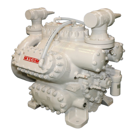
Configuration and Specification of Compressor Configuration of Compressor 2.1.1 Overall View of Compressor Fig. 2-1 Overall view (Ex: 6M) Description Description Compressor Base (Optional) Suction shut-off valve Belt cover (Optional) Discharge shut-off valve 10 Motor (Optional) Safety valve 11 Motor pulley (Optional) Flywheel (Optional) 12 V-belt (Optional) Oil cooler... -
Page 29: Cross-Sectional View Of Assembly
2.1.2 Cross-Sectional View of Assembly Fig. 2-2 Front view (4M) Fig. 2-3 Side view (4M) Fig. 2-5 Side view (6M) Fig. 2-4 Front view (6M) Reciprocating Compressor M Series... - Page 30 Fig. 2-6 Front view (8M) Fig. 2-7 Side view (8M) Reciprocating Compressor M Series...
-
Page 31: Oil Supply Mechanism
2.1.3 Oil Supply Mechanism Fig. 2-8 Oil supply mechanism Refrigerant oil is retained in the oil tank (a) at the bottom of crankcase. When the oil pump (c) is driven by the crankshaft, refrigerant oil in the oil tank (a) is suctioned via the oil strainer (b). -
Page 32: Unloader Mechanism
2.1.4 Unloader Mechanism Fig. 2-9 Unloader mechanism The capacity control (unloader) mechanism controls the operation of suction valve using unloader pistons. By controlling the operation of the suction valve, it changes the number of cylinders which compresses gas to change the suction capacity (performance). The details of mechanism are as below. -
Page 33: Specification Of Compressor
Remarks cover, oil cooler, and flywheel. *Please check with local Mayekawa/Mycom branch. Different shutoff valves are used in different locations. Do not exceed rating of shutoff valves even if compressor rating is greater. IE. North America uses Mayekawa shut off valves which are rated at 2.16MPaG (313 PsiG) 2.2.2... - Page 34 Item Limit value Remarks B region: When the evaporating 1200 rpm temperature is 15°C(59°F) 21°C(69.8°F) Minimum rotation 900 rpm *800 rpm (Contact MYCOM) Cooling water outlet temperature 50°C(122°F) or below Allowable temperature of blade hose Cooling water Clear water or brine Do not use seawater Degree of superheat: SH 20°C(68°F) or below...
-
Page 35: External Dimensions
2.2.3 External Dimensions Fig. 2-11 External dimensions (4M) Fig. 2-12External dimensions (6M) Fig. 2-13 External dimensions (8M) Reciprocating Compressor M Series... -
Page 36: Selection Of V / C-Belt
Selection of V-belt 60Hz (Motor : 6P or 4P x 60 Hz (1200 or 1750 rpm) , Center Distance : 1270 mm(50.00 Inch) Reciprocating Compressor M Series... -
Page 37: Installation
Installation Safety Precautions for Installation This chapter is based on the assumption that the compressor is installed for the purpose of refrigeration, cold storage, and air conditioning systems, recreational systems. If the specifications of your system are different, refer to this chapter and consider safety, before operation. -
Page 38: Installation Works
Installation Works 3.2.1 Unpacking Check that there is no abnormality such as damage on the compressor. If there are abnormalities or deficiencies on the compressor, please contact your local sales offices or service centers immediately. Unnecessary packing materials should be discarded according to the laws and ordinances, or your company's rules. - Page 39 Remove obstructions before lowering the compressor onto the ground. The compressor should not be tilted or unstable. Before lowering the compressor, notify others. When lowering the compressor onto two or more blocks, align the tops of blocks so that the compressor becomes stable horizontally on them.
-
Page 40: Preparation For Installation
3.2.4 Preparation for Installation Installation Space The figures below show the minimum necessary space for disassemble and reassemble of the compressor. Referring to these figures, secure space which allows easy operation, cleaning, maintenance, and inspection. Fig. 3-1 Installation space Reciprocating Compressor M Series... -
Page 41: Installation
Illumination Prepare illumination devices which allow easy operation, cleaning, maintenance, and inspection. Ventilation If natural ventilation is insufficient, install ventilation fans according to the regulations. Cooling Water Referring to chapter 7, secure cooling water necessary for your system. Piping Table 3-1 Connected piping list Suction gas With suction shut-off valve 4 inch... -
Page 42: Centering Of The Compressor/Driving Machine And Attachment Of The V/C-Belt
3.2.5.4 Centering of the Compressor/Driving Machine and Attachment of the V / C-belt To replace the V / C-belt with a new one, purchase the same set of belt as the current one, and replace the whole set at once. Even if their nominal dimensions are the same, their actual lengths may slightly differ. - Page 43 For centering use a straight edge on the side of flywheel and motor pulley. Centering standard: L=1 mm(0.04 inch) or less Fig. 3-3 Centering standard Loosen the slide base of motor and move the pulley closer to the compressor side, attach the V/C-belt to groove rotate on to the pulley.
- Page 44 Note 4: When the belt is under the minimum tension load, make sure that the belt does not move excessively by operation, because the load fluctuates due to the load conditions. After replacing the belt, operate the compressor for 2 to 3 hours, initial tension and friction will occur on the new belt.
-
Page 45: Piping
Retain the coupling/insert on the motor side on the spacer. When attaching the hub and coupling/insert on the motor side, move the hub to the gap in which the washers fit, and adjust the interval between the coupling hubs. If the washers do not fit in easily, or there are gaps between the coupling/insert, washers, and hub face, force in the axle direction (thrust) is applied. - Page 46 Cooling Water Piping Do not limit the flow in the cooling water system from the oil cooler to the head jacket. This is dangerous because the difference of pressure loss (resistance) restricts the cooling water flow, resulting in failure to cool necessary sections. Always flow cooling water during operation of compressor.
-
Page 47: Check After Installation
3.2.5.6 Charging of Refrigerant Oil Refer to "4.1.3 Initial Charging Method". 3.2.6 Check after Installation Referring to the items described below which should be performed after installation of compressor, formulate a list and procedure to check the refrigerating, cold storage, and air conditioning systems you use, based on their specification. -
Page 48: Documents Related To Installation *1
Documents Related to Installation * Note * : The followings are reference values of individual compressor. They may differ from the actual values. If there are any questions, please contact your local sales offices or service centers. Weight and Dimensions Fig. -
Page 49: Operation Of The Compressor
4.1.1 Precautions for Selecting Oil Brands to be used differ depending on the types of refrigerant. For details, contact your sales office or Mayekawa representative. Do not use the Polyolester (POE) oil. Do not use Hydro treated mineral oils Naphthenic based mineral oil of ISO VG 46-68 is recommended. -
Page 50: Initial Charging Method
4.1.2 Initial Charging Method When charging the oil initially or changing the oil after overhaul, charge the oil from the initial supply port to fill the oil cooler, oil filter, and oil passages with the oil. Description Oil supply port 4.1.3 Replenishment of the Oil The refrigerant oil level lowers gradually during the operation. -
Page 51: Oil Quantity
4.1.5 Oil Quantity Quantity of oil in the crankcase is judged by the oil level viewed through the oil sight glass. Symbol Oil Quantity Lower limit Standard Upper limit Reciprocating Compressor M Series... -
Page 52: Initial Operation
Initial Operation When approx. 24 hours have passed after the initial startup, foreign materials such as dust, scale, rust, and sand in the piping can accumulate in the compressor because they flow with the refrigerant gas. Fine foreign materials that cannot be removed by the suction filter will mix into the oil, resulting in failure or abnormal wear. Suction of foreign materials into the compressor will continue until all foreign material has been pulled into the compressor. - Page 53 Perform the initial operation according to "Table 4-1 Reference of the oil replacement and filter inspection". Reciprocating Compressor M Series...
-
Page 54: Operation Order Of The Unloader
Operation Order of the Unloader The figure, indicates the cylinder number, and indicates the unloader piston number. "ON" in the table indicates loading (energized), and "OFF" indicates unloading (not energized). Table 4-2 Loading rate (4M) Unloader Cylinder piston 100% number Stop Fig. -
Page 55: Operation Notices
Operation Notices Notices for operation are as follows. 4.4.1 Start/Stop Limitation To use the compressor normally, number of start/stop times and the stop time are specified as follows. Table 4-5 Specification for number of start/stop times and the stop time Item Qty. -
Page 56: Maintenance
Maintenance Safety Precautions for Maintenance Be careful so as not to receive an electrical shock when turning on/off the power of each unit. Before performing maintenance, turn off the motor (main power) and control power, and then perform lockout and tagout. Before performing maintenance, turn off the power of instruments such as a heater. -
Page 57: Periodic Inspection
Periodic Inspection Record the operation of the compressor, details of periodic inspection and maintenance in the operation log. By recording the operation logs correctly, the refrigerating, cold storage, and air conditioning systems can be operated efficiently and safely. This will be useful for investigating the cause immediately and adequately in case of equipment failure. -
Page 58: Monthly Inspection
5.2.2 Monthly Inspection Verify the operation of the pressure switch using a pressure tester. Do not increase the actual discharge pressure. Inspection Items Remarks Compressor Looseness of couplings Refer to "3.2.5.4 Centering of the Compressor/Driving Machine and Attachment of the belts". Belt tension Refer to "3.2.5.4 Centering of the Compressor/Driving Machine and Attachment of the belts". -
Page 59: Maintenance (Overhaul)
Maintenance (Overhaul) Frequency of the maintenance differs depending on the equipment model, refrigerant, number of rotations, usage, equipment status, and oil types. The parts are replaced at your expense even when they are damaged before the provided time has passed. Normally, replace the M series consumable materials at the maintenance (overhaul). -
Page 60: First Inspection
5.3.2 First Inspection Remove the shaft seal cover, head cover, and hand hole cover, then remove the piston and connecting rod. When no abnormality is found, it is not necessary to remove the crankshaft and bearing housing. Inspection Inspection Sections Remarks Items Plate valve... - Page 61 Refrigeration Oil Control Standard The oil, to which the control standard is applied, is classified as follows: Mineral oil: Naphthene series ISO–VG 46-68 Each item and standard is as follows. The control standard may be changed without notice depending on the performance.
-
Page 62: Disassembly/Assembly
Disassembly/Assembly 5.5.1 Exterior Equipment Release the residual pressure, and discharge the refrigerant oil from the crankcase. Drain the oil from the oil cooler. Part Part Steps Description Steps Description HT-19 Braided hose Mechanical lock HT-12 (Refer to "Attentions for Removing the Pipe, oil cooler Mechlock".) (Refer to "Attentions for Removing the Oil... -
Page 63: Removing The Oil Cooler Piping/Water Cooled Type Oil Cooler
5.5.1.1 Attentions for Removing the Oil Cooler Piping/Water Cooled Type Oil Cooler While removing the water cooled type oil cooler and oil cooler piping, the refrigerant oil remaining in the piping may leak from the connection port. Place a waste cloth over the connection port. -
Page 64: Assembly Of The Flywheel
5.5.1.5 Attentions for Attaching the Mechanical lock Do not use the grease containing molybdenum disulfide and the oil containing extreme-pressure agent when attaching the mechlock. Always wipe off the grease and foreign materials on the surface of the crankshaft axis and the joint surface of the flywheel before attaching the mechlock. Align the end surface of the crankshaft (a) with the flywheel (b). -
Page 65: Suction/Discharge Area
5.5.2 Suction/Discharge Area Part Part Steps Description Steps Description Shut–off valve, suction Thermometer, discharge side (Refer to "Attentions for Removing the Discharge manifold Suction/Discharge Shut–off Valve".) (Refer to "Attentions for Removing the Discharge Manifolds".) (Refer to "Attentions for Attaching the Suction/Discharge Shut–off Valve".) (Refer to "Attentions for Attaching the Discharge Manifolds".) -
Page 66: Removing The Suction/Discharge Shut-Off Valve
Removing the Discharge Manifolds The discharge manifolds weigh 73kg(160 lbs) (8M)/62 kg(137 lbs) (6M)/50kg(110 lbs) (4M). Handling it inappropriately may cause injury. Remove the discharge manifolds in an appropriate manner with at least one other person. For 6M, the discharge manifold hexagon... - Page 67 Attentions for Attaching the Discharge Manifolds The discharge manifolds weigh 73 kg(160 lbs) (8M)/62 kg(137 lbs) (6M)/50 kg(110 lbs) (4M). Handling them inappropriately may cause injury. Attach the discharge manifolds in an appropriate manner with at least one other person.
-
Page 68: Head Cover/Hand Hole Cover
5.5.3 Head Cover/Hand Hole Cover Part Part Steps Description Steps Description — Head jacket cover Discharge valve cage assembly (Refer to "Attentions for Removing the (Refer to "Discharge Valve Cage Head Jacket Cover/Hand Hole Cover".) Assembly".) (Refer to "Attentions for Attaching the Stud bolt, discharge valve cage 75-2 Head Jacket Cover/Hand Hole Cover".) -
Page 69: Removing The Head Jacket Cover
5.5.3.1 Removing the Head Jacket Cover Dropping of the head jacket cover may cause injury or damage to the compressor. Always attach the stud bolt before performing the work. To remove the head jacket cover, tap the cover lightly using a copper hammer or plastic hammer. Remove one of the head jacket cover hexagon head screws from the top, and attach the stud bolt (a). -
Page 70: Removing The Hand Hole Cover
Remove all but two stud bolts from the head cover (b) remove them diagonally as shown in the figure. Loosen the last two bolts (b), diagonally as shown in the figure, evenly to remove them. After removing the valve plate, remove the stud bolts (a). -
Page 71: Assembly Of The Head Cover
5.5.3.4 Attaching the Hand Hole Cover Dropping of the hand hole cover may cause injury or damage to the compressor. Always attach the stud bolts before performing the work. Because the attachment surface of the hand hole cover is facing obliquely downward, the cover may fall even when the stud bolts are used. -
Page 72: Assembly Of The Head Jacket Cover
5.5.3.6 Attaching the Head Jacket Cover Dropping of the head jacket cover may cause injury or damage to the compressor. Always attach the stud bolt before performing the work. After attaching the stud bolt (a) into the head jacket cover at the top, attach the head jacket cover. -
Page 73: Valve Plate/Piston Assembly/Cylinder Sleeve Assembly
5.5.4 Valve Plate/Piston Assembly/Cylinder Sleeve Assembly Part Part Steps Description Steps Description 77-S Valve plate Connecting rod (rod cap) (Refer to "Removing the Valve Plate".) (Refer to "Removing the Piston Assembly".) (Refer to "Attaching the Valve Plate".) (Refer to "Attaching the Piston 77-L Assembly".) 77-S... -
Page 74: Attachment Of The Spacer
5.5.4.1 Attachment of the Spacer Remove the coil screw from the integrated solenoid valve unloader cover to remove the coil. Loosen the unloader cover hexagon head bolt, and remove the unloader cover (a). With the spacer with thickness of 17—19 mm (0.66—0.75 inches) inserted between the unloader piston (b) and unloader cover (a), tighten the two unloader cover hexagon head screws manually. -
Page 75: Assembly Of The Cylinder Sleeve Assembly
5.5.4.4 Attaching the Cylinder Sleeve Assembly Align the sleeve positioning pin (a) with the groove on the case (b). While keeping the pin aligned with the groove, align the unloader push rod tab (c) with the cam ring notch (d). To check the attachment of the cylinder sleeve assembly, check the movement of the unloader push rod (piston). - Page 76 Attach the piston ring compressor (b) to the piston assembly (a). Face section A of the piston ring compressor shown in the figure towards the piston skirt. Rotate the crankshaft so that the piston assembly to be attached is positioned at the bottom of dead center.
-
Page 77: Assembly Of The Suction Plate Valve/Suction Valve Spring
Assemble the two connecting rod head bolts washers as shown in the figure. If the corner (a) of the connecting rod bolt washer baffle becomes obtuse, replace the washer. Tighten the connecting rod bolts gradually and evenly. Tighten the connecting rod bolts using the specified torque. 5.5.4.6 Attaching the Suction Plate Valve/Suction Valve Spring Support the suction valve plate and suction valve spring to the valve plate using clips (a). -
Page 78: Removal Of The Spacer
5.5.4.8 Removal of the Spacer Loosen the unloader cover bolts, and remove the unloader cover. Remove the spacer. Press the unloader piston with your hand to check that the unloader push rod moves. Align the crankcase (a) with the gasket (b), and drain hole (d) of the unloader cover (c) with the filler opening (e), then attach the gasket (b) and unloader cover (c). -
Page 79: Unloader
5.5.5 Unloader Part Part Steps Description Steps Description Coil (integrated solenoid valve Unloader push rod unloader cover) Retaining ring, unloader push rod Unloader cover (integrated solenoid Washer (No1), unloader push rod valve unloader cover) (Refer to "Attaching the Unloader Push Rod Washer".) (Refer to "Attaching the integrated Solenoid Valve Unloader Cover ".) -
Page 80: Assembly Of The Unloader Push Rod Washer
5.5.5.1 Assembly of the Unloader Push Rod Washer Unloader push rod washer (No.1) (a), unloader push rod washer (No.2) (b), and unloader push rod washer (No.3) (c) differ as shown in the figure. 5.5.5.2 Assembly of the Unloader Push Rod There are five types of the unloader push rod depending on its length. -
Page 81: Seal Cover/Mechanical Seal/Oil Seal
5.5.6 Seal Cover/Mechanical Seal/Oil Seal Part Part Steps Description Steps Description Seal cover assembly "O"ring, mechanical seal collar (Refer to "Removing the Seal Cover "O"ring, oil seal retainer Assembly".) Retainer, oil seal (Refer to "Attentions for Assembly of the (Refer to " Removing the Oil Seal Seal Cover".) Retainers".) (Refer to "Disassembly/Assembly of the... -
Page 82: Removing The Seal Cover Assembly
5.5.6.1 Removing the Seal Cover Assembly Dropping of the seal cover assembly may cause injury or damage to the compressor. Always attach the stud bolts before performing the work. Be careful not to damage the mechanical seal collar. To remove the seal cover assembly, insert the seal cover assembly screws into the service holes (b) and tighten them. -
Page 83: Assembly Of The Mechanical Seal Collar
5.5.6.5 Assembly of the Mechanical Seal Collar Position the mechanical seal collar set screw (a) to the front (collinear position) of the set screw hole (b) on the crankshaft. Lightly tighten the set screws (a) at the two sections of the mechanical seal collar, and slightly loosen them when the screws contact the crankshaft. -
Page 84: Main Bearing Head Assembly/Oil Pump Assembly/Oil Filter Assembly
5.5.7 Main Bearing Head Assembly/Oil Pump Assembly/Oil Filter Assembly Part Part Steps Description Steps Description Oil filter assembly Main bearing head assembly — (Refer to "Oil Filter Assembly".) (Refer to "Removing the Main Bearing Head Assembly".) "O"ring, oil filter head Oil pump assembly (Refer to "Assembly of the Main Bearing Head Assembly".) -
Page 85: Removing The Main Bearing Head Assembly
5.5.7.1 Removing the Main Bearing Head Assembly The main bearing head assembly weighs 50 kg(110.3 lbs). Handling it inappropriately may cause injury. Remove the main bearing head assembly in an appropriate manner with at least one other person. Dropping of the main bearing head assembly may cause injury or damage to the compressor. -
Page 86: Crankshaft
5.5.8 Crankshaft Part Part Steps Description Steps Description 29-1 Crankshaft Thrust roller bearing (shaft side) (Refer to " Removing the Crankshaft".) (Refer to "Assembly of the Thrust Roller Bearing (Shaft Side)".) (Refer to "Assembly of the Crankshaft".) Thrust roller bearing (roller) 29-1 Remove the parts in the order shown in the figure. -
Page 87: Removing The Crankshaft
5.5.8.1 Removing the Crankshaft The crankshaft weighs approx. 140 kg(308 lbs). Handling it inappropriately may cause injury. Remove the crankshaft in an appropriate manner with at least two other people. Affix curing tape onto the attachment surface of the crankshaft flywheel so that it is not scratched. Ensure you have two people and blocks of V shaped wood to lower the crankshaft onto. -
Page 88: Assembly Of The Thrust Roller Bearing (Shaft Side)
5.5.8.2 Assembly of the Thrust Roller Bearing (Shaft Side) Attach the thrust roller bearing (shaft side) (a) and thrust roller bearing (bearing head side) (b) into the correct positions. See diagram. Face a flat surface (d) of the thrust roller bearing (shaft side) (a) towards the thrust roller bearing (roller) (c). -
Page 89: Assembly Of The Crankshaft
5.5.8.3 Assembly of the Crankshaft The crankshaft weighs approx. 140 kg(308 lbs). Handling it inappropriately may cause injury. Attach the crankshaft in an appropriate manner with at least two other people. Attach the coupling rod (a) (or an M20 bolt with a sufficient length) into the screw hole at the end of the crankshaft at the main bearing head side. -
Page 90: Bearing Head
5.5.9 Bearing Head Part Part Steps Description Steps Description Bearing head Thrust roller bearing (bearing head 29-1 (Refer to " Removing the Bearing Head".) side) "O"ring, bearing head 24-1 (Refer to "Assembly of the Bearing Main bushing (bearing head side) 12-2 Head".) (Refer to "Replacing the Main Bushing... -
Page 91: Removing The Bearing Head
5.5.9.1 Removing the Bearing Head Dropping of the bearing head may cause injury or damage to the compressor. Always attach the stud bolts before performing the work. To remove the bearing head, insert the bearing head hexagon head bolts into the service holes (a) and tighten them. -
Page 92: Assembly Of The Bearing Head
5.5.9.4 Assembly of the Bearing Head Dropping of the bearing head may cause injury or damage to the compressor. Always attach the stud bolts before performing the work. After attaching the stud bolts into the bearing head for two sections at the top, attach the bearing head. -
Page 93: 5.5.10 Discharge Valve Cage Assembly
5.5.10 Discharge Valve Cage Assembly Part Part Steps Description Steps Description Retainer, discharge valve seal bolt 112-2 Spring, discharge valve (Refer to "Assembly of the Discharge Discharge valve seat Valve Spring".) Parallel pin, discharge valve sheet Discharge plate valve Discharge valve cage Smooth the discharge valve sheet screw baffle. -
Page 94: 5.5.11 Piston Assembly
5.5.11 Piston Assembly Part Part Steps Description Steps Description Retaining ring, piston pin Piston ring (2nd) Piston pin (Refer to "Assembly the Piston Rings".) Piston Connecting rod (rod) Oil control ring (3rd) (Refer to "Assembly of the Piston Rings".) Piston ring (1st) Coil (Refer to "Assembly of the Piston Rings".) Bushing, connecting rod... -
Page 95: 5.5.11.2 Assembly Of The Piston Rings
5.5.11.2 Assembly of the Piston Rings Attach the piston ring (1st) and piston ring (2nd) so that the side with a marking (R mark) faces upwards. Entry of oil may occur. Attach the piston ring (1st) (a) and piston ring (2nd) (b) so that the side with a marking (R mark) (e) faces upwards. -
Page 96: 5.5.12 Cylinder Sleeve Assembly
5.5.12 Cylinder Sleeve Assembly Part Part Steps Description Steps Description 62 or Stop ring, lift pin Cam ring (Refer to "Assembly of the Cam Ring".) Lift pin Spring, lift pin "O"ring, cylinder sleeve Spring pin, cylinder sleeve 61-1 Retaining ring Remove the parts in the order shown in the figure. -
Page 97: 5.5.13 Seal Cover Assembly
5.5.13 Seal Cover Assembly Part Part Steps Description Steps Description Shower flushing sleeve 41-1 Mechanical seal mating ring (Refer to "Removing the bellows oil (Refer to "Assembly of the Mechanical sleeve".) Seal Mating Ring".) (Refer to "Assembly the bellows oil "O"ring, mechanical seal mating ring Sleeve".) "O"ring, bellows oil sleeve... -
Page 98: 5.5.13.2 Assembly Of The Mechanical Seal Mating Ring
5.5.13.2 Assembly of the Mechanical Seal Mating Ring Align the pin (a) of the mechanical seal mating ring with the seal cover groove (b). 5.5.13.3 Attentions for Attaching the Bellows Oil Sleeve Face the drain hole of the bellows oil sleeve ( 11) (a) upwards. -
Page 99: 5.5.14 Main Bearing Head Assembly
5.5.14 Main Bearing Head Assembly Part Part Steps Description Steps Description Hexagon head plug, magnet 119-3 Blow-by gas plate Spacer, magnet 119-4 Gasket, blow-by gas plate Magnet 119-1 Main bushing (pump side) 12-1 (Refer to "Replacing the Main Bushing Oil pressure regulating valve (Pump Side)".) Thrust washer (pump side) (Refer to "Assembly of the Thrust Washer... -
Page 100: 5.5.15 Oil Filter Assembly
5.5.15 Oil Filter Assembly Part Part Steps Description Steps Description Oil filter case (bottom) "O"ring, oil filter element 14-2 Oil filter case "O"ring 14-3 Oil filter case (top) 14-1 "O"ring, oil filter element Remove the parts in the order shown in the figure. Attach the parts in the reverse order of removal. -
Page 101: Troubleshooting Troubleshooting Table
Troubleshooting Troubleshooting Table 1. Motor does not operate. Features Causes Results Countermeasures Motor beats and Motor failure Breakers have Inspect and repair or replace does not start. tripped. Motor is burnt. Belt tension is too high. Breakers have Adjust tripped. Motor is burnt. - Page 102 Features Causes Results Countermeasures Motor stops in a OP (oil pressure failure Cannot be short time after protection equipment t) is operated. starting. activated. Sliding surface of the Refrigerant oil is run down. Supply oil. compressor is (b) Oil pressure is low. Adjust the oil pressure.
- Page 103 2. Abnormal high pressure Features Causes Results Countermeasures Condenser Cooling water shortage or HP is activated Increase the volume of cooling temperature is cooling water temperature is or the safety water. Or, lower the cooling water warmer than usual. excessively high. valve is opened temperature.
- Page 104 3. Discharge pressure is too low. Features Causes Results Countermeasures Condenser and Amount of cooling water is Power Adjust the regulating valve. receiver are cold. excessive. Or, cooling water consumption is temperature is low. low and is in extremely good condition.
- Page 105 5. Suction pressure is too low. Features Causes Results Countermeasures Refrigerator room Refrigerant shortage or Does not Fill with refrigerant or adjust temperature or expansion valve is throttled too become cold operation. brine temperature much. is higher than suction pressure. Liquid back Cooling pipe is filled with Does not...
- Page 106 7. Crankcase is heated. Features Causes Results Countermeasures Head cover is Compression ratio has Oil is burnt, Increase cooling water for overheated. increased. carbon has condenser. Or, higher the cooling (High discharge (Condensed temperature adhered. water temperature. pressure, high has increased or refrigerant suction pressure) load has increased.) Refrigerant oil is burnt...
- Page 107 8. Excessive oil consumption Features Causes Results Countermeasures Crankcase tends to Forming of refrigerant occurs Cannot be Adjust operation. be frosted. due to liquid back. Especially operated during vacuum operation There is no other Pressure equalizer hole of the Oil hammer Inspect and clean, or clean the error.
- Page 108 9. Does not become cold Features Causes Countermeasures Suction pressure does Deficiency in performance Inspect and expand if the condition not become low. is normal. (a) Refrigerating machine Expansion (b) Cooling pipe Expansion Inspect and expand if the Condenser condition is normal. Load has increased.
-
Page 109: Related Document
Related Document Development View and Configuration Table of the Parts Fig. 7-1 Development view of M series cylinder part Reciprocating Compressor M Series... - Page 110 Fig. 7-2 Development view of parts around the 6M case and parts common with others (1/2) Reciprocating Compressor M Series...
- Page 111 Fig. 7-3 Development view of parts around the 6M case and parts common with others (2/2) Reciprocating Compressor M Series...
- Page 112 Fig. 7-4 Development view of parts around the 4M case Reciprocating Compressor M Series...
- Page 113 Fig. 7-5 Development view of parts around the 8M case Reciprocating Compressor M Series...
- Page 114 Table 7-1 Configuration table of the parts Qty. Part Part name Number Crankcase Crankshaft Drag crank Mechlock Main bearing head Gasket, main bearing head Hexagon head bolt, main bearing head 12-1 Main bushing (pump side) 12-2 Main bushing (seal side) Spring pin, thrust washer Oil filter assembly 14-1...
- Page 115 Part Qty. Part name Number Retaining ring "O"ring, cylinder sleeve Lift pin Spring, lift pin Stop ring, lift pin Suction plate valve Spring, suction valve Valve plate 73-3 Parallel pin, valve plate 73-4 Gasket, valve plate 73-5 Hexagon head bolt, valve plate 75-2 Stud bolt, discharge valve cage 77-SAssy Connecting rod (No.1)
- Page 116 Qty. Part Part name Number Suction filter cover Gasket, suction filter cover Hexagon head bolt, suction filter cover Oil sight glass "O"ring, oil sight glass Hexagon head bolt, oil sight glass Discharge manifold Gasket, discharge manifold 170L Hexagon head bolt (No.1), discharge manifold 170M Hexagon head bolt (No.2), discharge manifold 170S...
- Page 117 Qty. Part Part name Number HT-9 Connection (I- HT-10 Connection (I- HT-11 Connection (I- HT-12 Pipe, oil cooler HT-13 Pipe, oil drain HT-14 Pipe, seal drain HT-15 Hose nipple (R3/8) HT-16 Hose nipple (R3/4) HT-17 Street elbow (R3/4×Rc3/4) HT-18 Hose band (20A) HT-19 Blade hose (20A) HT-20...
-
Page 118: List Of Tightening Torques For Bolts And Nuts
List of Tightening Torques for Bolts and Nuts Table 7-2 List of tightening torques for bolts and nuts Part Qty. Tightening torque Part name 4M 6M 8M lbf·ft kgf·cm Hexagon head bolt, main bearing 88.5 1200 head 307 Hexagon socket head cap screw, 29.5... -
Page 119: List Of Tools For Disassembly
List of Tools for Disassembly Table 7-3 List of tools for disassembly Tool name Simplified diagram Specification/Size Qty. Remarks Socket wrench 10 mm 12.7 square drive 13 mm 17 mm 19 mm 24 mm Spinner handle 300 mm 12.7 square drive Torque wrench 12.7 square drive Hexagon wrench... - Page 120 Tool name Simplified diagram Specification/Size Qty. Remarks Suction disk For attaching piston assembly Piston ring compressor For attaching piston assembly Clip Suction valve retainer Stud bolt M16×150 mm Retain the covers Coupling rod M20×550 mm For removing/attaching crankshaft Spacer 46 mm For pressing unloader t30 19 mm Sponge...
-
Page 121: Vibration And Sound Data
Vibration and Sound Data 7.4.1 Vibration Standard Value for Vibration/Applied The standard value of vibration can be applied when evaluating the vibration of the reciprocating compressor installed in the unit. Upon the rated rotation speed of the compressor, note that this standard is based on the assumption that the frames and the piping are not resonated. -
Page 122: Sound Data
7.4.2 Sound Data Measurement Position of Sound Data Fig. 7-6 Measurement position of sound data (6M) Measurement Condition and Sound Data (For Reference) Table 7-5 Measurement condition and value of sound data (NH , Tc/Te=35/ 15°C) Refrigerant Suction pressure (MPaA) 0.237 Discharge pressure (MPaA) -
Page 123: Oil Cooler Heat Rejection (Ohr)/Head Jacket Heat Rejection (Jhr) (N4M, N6M, N8M)
Oil Cooler Heat Rejection (OHR)/Head Jacket Heat Rejection (JHR) (N4M, N6M, N8M) Reciprocating Compressor M Series 7-15... - Page 124 Reciprocating Compressor M Series 7-16...
- Page 125 Reciprocating Compressor M Series 7-17...
- Page 126 Reciprocating Compressor M Series 7-18...
- Page 127 Reciprocating Compressor M Series 7-19...
- Page 128 Reciprocating Compressor M Series 7-20...
- Page 129 Reciprocating Compressor M Series 7-21...
- Page 130 Reciprocating Compressor M Series 7-22...
- Page 131 Reciprocating Compressor M Series 7-23...
-
Page 132: Starting Torque
0.8MPaG 0.6MPaG 0.4MPaG 0.2MPaG 0 MPaG 1000 1500 Rotation Speed [rpm] Fig. 7-7 Characteristics of starting torque (4M) Table 7-6 Characteristics of starting torque (4M) Suction pressure when starting [MPaG] Rotation Torque [N·m] speed (rpm) 1500 Reciprocating Compressor M Series... - Page 133 Characteristics of Starting Torque (6M) Suction pressure when starting 0.8MPaG 0.6MPaG 0.4MPaG 0.2MPaG 0 MPaG 1000 1500 Rotation Speed [rpm] Fig. 7-8 Characteristics of starting torque (6M) Table 7-7 Characteristics of starting torque (6M) Suction pressure when starting [MPaG] Rotation Torque [N·m] speed (rpm) 1500...
- Page 134 Characteristics of Starting Torque (8M) Suction pressure when starting 0.8MPaG 0.6MPaG 0.4MPaG 0.2MPaG 0 MPaG 1000 1500 Rotation Speed [rpm] Fig. 7-9 Characteristics of starting torque (8M) Table 7-8 Characteristics of starting torque (8M) Suction pressure when starting [MPaG] Rotation speed (rpm) Torque [N·m] 1500...
-
Page 135: Parts Inspection And Replacement Standards
Parts Inspection and Replacement Standards Suction Filter/ Oil Strainer/ Oil Filter When cleaning the metallic mesh, inspect if the meshes are torn or soldered part is separated. If defects are found, always repair or replace it with a new one. Special flux must be used for soldering stainless steel parts. - Page 136 Measure the inner diameter of the shaft hole at the small end of the connecting rod. If the inner diameter of the shaft hole exceeds the usage limit, replace the connecting rod bushings. Standard Usage limit Measurement point dimensions (mm) (mm) Inner diameter of the shaft hole at the small 45.1...
- Page 137 Inspect the surface of the inner/outer periphery of the discharge plate valve and suction plate valve for scratches. If there are scratches on the surface of the inner/outer periphery, replace the discharge plate valve and suction plate valve. Though wear of contact surface to valve seat of the discharge plate valve and suction plate valve are within the wear limit, if there are scratches on the surface of inner/outer periphery, fatigue crack on the valves may result.
- Page 138 Piston/ Piston Pin/ Piston Ring Inspect the piston for scratches. If scratches are found, repair it by using a grinding stone. If scratches are found in the outer surface, repair it by grinding the surface at a right angle of the sliding direction, using a grinding stone.
- Page 139 Oil Pump If the oil pressure is low though the oil pressure adjustment valve is closed during the operation, and if the cause is not the clogging of the oil filter, there may be wear on the gears, metals, and shafts of the oil pump. Remove the pump from the compressor, hold the shaft of the pump, and inspect the shaft for looseness by moving it to the axial direction or right angle of the axial direction.
- Page 140 Gasket List Gaskets cannot be reused. Always replace with a new gasket. Fig. 7-11 Gasket list Part Qty. Part name Number Gasket, main bearing head Gasket, bearing head Gasket, shaft seal cover Gasket, hand hole cover Gasket, head cover Gasket, oil pump 73-4 Gasket, valve plate Gasket, unloader cover...
- Page 141 "O"ring List "O"rings cannot be reused. Always replace with a new "O"ring. Fig. 7-12 "O"ring list Part Qty. Part name Number 14-2 "O"ring, oil filter element 14-3 "O"ring, oil filter case "O"ring, Oil filter head 24-1 "O"ring, bearing head "O"ring, oil seal retainer "O"ring, mechanical seal collar 41-2...
Need help?
Do you have a question about the 4M and is the answer not in the manual?
Questions and answers