Table of Contents
Advertisement
Quick Links
Advertisement
Table of Contents

Summary of Contents for Autopilot Kanardia
- Page 1 Autopilot — Installation Manual Kanardia d.o.o. November 2020 Revision 2.1...
- Page 3 In short, the license gives you right to copy, reproduce and modify this document if: ˆ you cite Kanardia d.o.o. as the author of the original work, ˆ you distribute the resulting work only under the same or similar license to this one.
- Page 4 Autopilot Installation Manual Revision Date Description Aug 2015 Initial release. Maj 2016 Tuning notes were added. Jul 2016 Tuning table expanded. Feb 2020 Complete Manual rework. Nov 2020 Updated for changes in software version 3.8, Amigo and Nesis/Aetos windows. ©...
-
Page 5: Table Of Contents
4.1 Overview ......17 4.2 Autopilot Settings ......17 4.2.1... - Page 6 Autopilot Installation Manual CONTENTS 5 Tuning 5.1 Controller ......26 5.1.1 PID controller .
- Page 7 Autopilot Installation Manual CONTENTS A Autopilot Installation And Tuning Form B Parameters For Known Airplanes B.1 Ekolot Topaz ......48 B.2 Pipistrel Sinus .
-
Page 8: Introduction
Intended Use The autopilot is designed to help a pilot in stable, controllable flight conditions during cruising. If such conditions are met, the autopilot can be engaged to take some relief from the pilot, who can perhaps focus a bit more on ATC communication or to do some navigation task. -
Page 9: Operation Limitations
ˆ Information from the Aircraft Operating Handbook always supersedes information given in this manual. ˆ The autopilot is designed to be used only in cruising conditions. It will not work at low and high speeds. It can’t fly approaches and departures and it can’t do takeoffs and landings. -
Page 10: Nesis/Aetos Based Minimal System
ˆ A communication system that connects all devices and allow information exchange in real time. In Kanardia autopilot case, there are two different solutions for an autopilot minimal system. 1.4.1... -
Page 11: Principle Of Operation
This means that autopilot has four loops: pitch and vertical speed loops are used for elevator, while heading and roll loops are used for aileron. All these loops must be properly tuned to achieve requested autopilot operation. Var- ious experimental values in the form of tuning parameters are provided at the end of the document. -
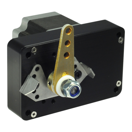
Page 12: Servo Motor
Autopilot Installation Manual 2.1 Servo Motor must be obeyed to have a working and safe autopilot system. The installa- tion information in this section is extremely important and must be clearly understood by the installer. Improper servo installation or failure to observe and diagnose installation problems prior to flight can result in extremely serious consequences, including... -
Page 13: Servo Arm
Autopilot Installation Manual 2.2 Servo Arm Servo Arm Servo arm has multiple holes for mounting control rod. The hole in use should be chosen to maximize the arm rotation. Servo arm should not be removed or replaced without Kanarida advise. The removal of servo arm includes removal of safety pin. -
Page 14: Servo Arm Safety Pin
If safety pin is broken or it gets slack the whole autopilot system must be checked. Only after the cause of the problem was found and corrected, safety pin can be replaced with a new pin. -
Page 15: Can Bus
Autopilot Installation Manual 3.2 CAN Bus The autopilot switch must be easily accessible by the pilot. The pilot must be able to reach it in any moment. CAN Bus Servo motor must also be connected to the CAN bus. The controller module is built in the servo housing. -
Page 16: Autopilot Quick Disconnect
In the case of Amigo, no configuration is necessary. 3.3.2 Autopilot Level The same button can be used also used for the autopilot level command. This command will activate Track Hold mode for aileron and Altitude Hold mode for elevator. -
Page 17: Overview
AP to operate. This is a very important safety feature. 4. Autopilot controller parameters are set. Most of them can be set on the ground, but some must be adjusted during flight tests. 5. Autopilot is tuned, which is the most difficult part. This can be per- formed only in flight. -
Page 18: Servo Configuration
Autopilot Installation Manual 4.2 Autopilot Settings In Amigo, press and hold the ALT knob and then select the Autopilot from the menu. Figure 5 shows the main autopilot settings menu. Nesis/Aetos version is on the left and the Amigo version is on the right. This pattern repeats throughout this section. - Page 19 Autopilot Installation Manual 4.2 Autopilot Settings Select the servo to configure. A selection example is shown on Figure 6. Figure 6: An example of servo selection based on serial number. Once serial number is selected a window with servo details opens, Figure 7.
-
Page 20: Ground Test
5 are also in use.) This is servo motor characteristics and shall not be changed. In general, PPR, Reduction and Max speed shall not be changed and original values shall be kept. Change them only if Kanardia support team approves the changes. 4.2.2 Ground Test The ground test is used to check correct servo motor movement. -
Page 21: Operation Limits
The limits shall be defined by the airplane producer. These autopilot limits are much, much stricter than airplane capabilities. The limits are set around stable, coordinated flight at the economy cruise speed. As soon as any parameter goes out of the limits, autopilot will be disconnected. © Kanardia 2016-2020... - Page 22 VNE. Max VS . . . set maximal allowed rate of climb or descent. Max roll . . . maximal allowed roll for autopilot operation. Set this to 35 or less. Max pitch . . . maximal allowed pitch for autopilot operation. Set this to 12 or less.
-
Page 23: Controller Parameters
This angle shall be smaller than max pitch from the limits, section 4.2.3. Roll target is the maximal roll that can autopilot require in order to change direction. This angle shall be smaller than max roll from the limits, section 4.2.3. -
Page 24: Tuning
Here only window description is given. Please refer to the section 5.5 for details about the tuning procedure. When the Tuning option is selected from the Autopilot menu, a window il- lustrated on Figure 11 appears. Select one of four autopilot control loops to tune. - Page 25 Autopilot Installation Manual 4.2 Autopilot Settings Figure 11: Selection of an autopilot control loop. Once loop was selected, a tune window appears. This window allows changing the PID controller parameters and observing the response at the same time. Figure 12 illustrates the example.
-
Page 26: Tuning
Autopilot Installation Manual 5. Tuning Tuning Each autopilot must be taught how to fly a plane. This is done during tuning procedure. The following section provides you with a necessary knowledge how to properly tune the aircraft autopilot. The tuning of the autopilot is based on trial and error method. The operator has to gain knowledge and experience. -
Page 27: Step Change And Response
Autopilot Installation Manual 5.2 Step Change and Response Typical block representation of the controller with feedback is shown on fig- ure 13. The input to PID controller is the difference between reference and measured process value. Output of the controller must control the process to reduce the difference. -
Page 28: Cascade Controller
Autopilot Installation Manual 5.3 Cascade Controller 2. Overshoot. 3. Steady-state error - remaining error. 4. Response time - 90% of reference step. 5. Oscillations. Cascade Controller The main problem of the aircraft control is the fact that the aircraft is a complex process. -
Page 29: Backlash
Tuning Procedure The tuning of the autopilot requires a ground preparation and a flight testing. 5.5.1 On-Ground Before first flight the operator shall enter appropriate initial values for the... -
Page 30: In-Flight
flight path, good visibility, no airspace conflicts, etc. It is highly recommended that you bring someone along on the autopilot test flight. At many points the pilot’s attention will be divided between documentation, tuning autopilot, and maintaining situational awareness. -
Page 31: In-Flight Tuning
In-Flight Tuning Kanardia autopilot system uses two-axis control: elevator and aileron. The tuning of autopilot is divided into two independent tasks. The operator shall tune the elevator control first and then move to aileron control tuning. Please note that during the tuning of the elevator the pilot is responsible to maintain roll angle of the aircraft and take care for direction as well. -
Page 32: Pitch Tuning
When reaching target altitude and cruising speed make sure the aircraft is trimmed properly for a level flight. The operator shall enter the Tune dialog for pitch loop as shown in figure 12. By default the autopilot servo motor is in disengaged state. The autopilot engages every time the operator selects new Reference value and disengages every time the operator changes any of the P-, I- or D- term. - Page 33 Autopilot Installation Manual 6.1 Elevator I-term shall be set to start value. Tune it following flow chart shown in figure 6.1.1. Start with high I-term and then gradually decrease it, until you reach satisfactory response. I-term will add some oscillations, do not worry about this for now. The D-term should damp it enough.
- Page 34 Autopilot Installation Manual 6.1 Elevator 1. Set 0 degrees reference angle. D = 0.0 s 2. Steady state - Wait enough time for con- troller to stabilize. Around 10 seconds Set Reference to 0° usually is enough. 3. Step change - Change reference angle by Wait 10 seconds 3-5 degrees.
- Page 35 Autopilot Installation Manual 6.1 Elevator (a) P too low. (b) P still too low. (c) P ok - Small overshoot. (d) Start I for pitch is 8s. (e) Lower I - better. (f) Lower I - even better. (g) Add D=I/20.
-
Page 36: Vertical Speed Tune
P-term is too high. You will have to decrease it to the half of the current value. Problems In case that it is impossible to tune the autopilot there is a great chance that you are experiencing one of the basic controller problems described in 5.4. - Page 37 I-term /5. Testing After tuning the operator should test the PID -terms with different vertical speeds, both in climb and in descend. Please note the autopilot will not automatically adjust the airspeed. If the airspeed is too high or too low the autopilot will disengage.
- Page 38 Autopilot Installation Manual 6.1 Elevator (a) P way too low. (b) P still too low. (c) P still too low. (d) P is now just enough. (e) Start value for I. (f) Lower I - even better. (g) I should be ok.
-
Page 39: Aileron Tune
If this parameter is set to 1.0 this means that autopilot will try to correct the error of 5 with an roll rate of 5 /s. For start it should be set to 1.0. This value is fine for most installations. -
Page 40: Heading Tune
Autopilot Installation Manual 6.2 Aileron tune (a) P way too low. (b) P still too low. (c) P still too low. (d) P is now just enough. (e) Start value for I. (f) Lower I - oscilations - go-back. (g) Test into other direction. -
Page 41: Fine Tuning
For most ultra-light aircraft’s it should be around 0.2 and 0.3. For start it should be set to 0.1. Now with autopilot in level mode change autopilot heading. If the aircraft still dives when initiating turn you should increase the this parameter by 0.1 and re test. -
Page 42: Motor Power
This will reduce the current consumption of the motor and it will reduce the motor heating. Also the pilot will be able to override the autopilot with more appropriate force. Quick Configuration This is a quick reminder of Nesis/Aetos commands inputs required to config- ure the autopilot system for a know airplane. -
Page 43: Configure Servos
ˆ Maximum Pitch: 12 Values shown above are given for example only – use appropriate limits for your airplane. If the aircraft exceeds this limits the autopilot will disengage immediately and the reason will be shown on the display. ©... -
Page 44: Tuning
ˆ Heading Manual Tune Please fill the report from appendinx A once the installation and tuning is complete and send the form to Kanardia. The form is needed for future references and maintenance purposes. Safety Measures Autopilot system is not terrain or traffic aware and it will not make... -
Page 45: Automatic Disable
The following ways may be used to disable autopilot system manually: 1. Select the Disable option from the autopilot menu of Nesis/Aetos. 2. On Nesis/Aetos, press the User button when the autopilot menu is active (double click on user button). -
Page 46: Electrical Disable
8.3 Electrical Disable Electrical Disable The autopilot motors are disconnected as soon as power supply is removed. Therefore it is essential that the power to the servo motors can be cut with removable fuse or with a separate switch. See section 3.1 for more details. -
Page 47: A Autopilot Installation And Tuning Form
Autopilot Installation Manual A. Autopilot Installation And Tuning Form Autopilot Installation And Tuning Form Date Airplane/Type Customer Registration Performed by Signature Servo motor settings Setting Elevator Aileron Setting Elevator Aileron Model Reversed Lever Power Lever hole Hold pwr Backlash Reduction... -
Page 48: B Parameters For Known Airplanes
Tables in this section list the tuning parameters for autopilots we have in- stalled in different airplanes. If your installation is identical, then these values should give you a very reasonable autopilot behavior. However, when the hardware installation is a bit different (usually, it is) or if different servo arm was used or a different hole in the servo arm, etc, then... -
Page 49: Aeropilot Legend 540
Autopilot Installation Manual B.3 Aeropilot Legend 540 Table 3: Sinus configuration parameters Max arm mv Max pitch rate 5 /s Pitch target Max roll rate 3 /s Roll target Max VS rate 1.5m/s VS target 3m/s Turn comp Roll rate gain... -
Page 50: Aerospool Dynamic Wt9
Autopilot Installation Manual B.5 Aerospool Dynamic WT9 Table 7: EV97 configuration parameters Max arm mv Max pitch rate 3 /s Pitch target Max roll rate 5 /s Roll target Max VS rate 1.5m/s VS target 3m/s Turn comp Roll rate gain... -
Page 51: Aeroprakt
Autopilot Installation Manual B.7 Aeroprakt Table 11: NG6 configuration parameters Max arm mv Max pitch rate 3 /s Pitch target Max roll rate 3 /s Roll target Max VS rate 1.0m/s VS target 2.5m/s Turn comp Roll rate gain disabled... -
Page 52: Comco Ikarus
Autopilot Installation Manual B.9 Comco Ikarus Table 15: TG configuration parameters Max arm mv Max pitch rate 2 /s Pitch target Max roll rate 3 /s Roll target Max VS rate 1.0m/s VS target 2.5m/s Turn comp Roll rate gain...
Need help?
Do you have a question about the Kanardia and is the answer not in the manual?
Questions and answers