Table of Contents
Advertisement
Quick Links
Advertisement
Table of Contents

Related Manuals for Shini SGB Series

Summary of Contents for Shini SGB Series
- Page 1 series Gravimetric Blender Date: Dec. 2017 Version: Ver. C (English)
-
Page 3: Table Of Contents
Contents General Description ..................9 1.1 Coding Principle ..................10 1.2 Feature ....................10 1.3 Technical Specifications ................ 12 1.3.1 Technical Specifications .............. 12 1.3.2 Specifications ................13 1.4 Safety Regulations ................16 1.4.1 Safety Rules for Touch Screen ........... 16 1.4.2 Safety Signs and Labels ............. - Page 4 4.1 Starting Up..................... 33 4.1.1 Turn on the Main Power Switch ..........33 4.2 Interface Operation Flow ............... 33 4.3 About Keyboard Interface ..............35 4.3.1 Input and Edit Alphabetic and Numerical Value ......35 4.3.2 Alternative Options ..............36 4.4 Log in/out ....................
- Page 5 4.8.1 Appendix 4: Chromatic Aberration Compensation of Reclaimed Material ....................63 4.8.2 Appendix 7: Blending Motor Locked-rotor Inspection Switch ..63 4.9 Control Mode ..................64 4.9.1 Weighing Metering Mode ............64 4.9.2 Volumetric (Time) Metering Mode ..........64 4.9.3 Mixing Metering Mode ..............65 Trouble-shooting ..................
- Page 6 Table 4-3:List of Administrator Login Screen ............ 37 Table 4-9:List of Formula Setting Screen ............43 Table 4-13: List of User Management Screen ..........50 Table 4-14:List of Manual Mode Screen ............51 Table 4-16:List of Alarm Checking Screen ............54 Picture Index Picture 1-1: Technical Specifications ..............
- Page 7 Picture 4-13: Weighing Data Display Interface 2 ..........42 Picture 4-14: Recipe Setting Interface ..............43 Picture 4-15: Recipe Elements ................44 Picture 4-16: Menu Selection ................46 Picture 4-17: Parameter Setting Interface ............47 Picture 4-18: IP Setting Interface ................ 48 Picture 4-19: Weightlessness Parameter Interface ..........
- Page 8 8(73)
-
Page 9: General Description
Read this manual carefully before operation to prevent damage of the machine or personal injuries. SGB series gravimetric blender can be used in the fields of injection molding machines, blow molding machines and extrusion lines for proportionally precise mixing of several types of material. This series machines adopt Becca levy PLC controller and latest ingredients calculation methods. -
Page 10: Coding Principle
1.1 Coding Principle 1.2 Feature 1) Standard configuration The micro-scale metering accuracy is ±0.1% when all materials are blended through gravity. Auto calibration function which is performed every time after material weighting ensures best proportioning accuracy. Up to 100 recipes can be stored for future use. ... - Page 11 Chapter 6, which contains service instructions intended for service engineers. Other chapters contain instructions for the daily operator. Any modifications of the machine must be approved by SHINI in order to avoid personal injury and damage to machine. We shall not be liable for any damage caused by unauthorized change of the machine.
-
Page 12: Technical Specifications
1.3 Technical Specifications 1.3.1 Technical Specifications SGB-40 SGB-200 SGB-600 SGB-1200 SGB-2000 SGB-3000 Picture 1-1: Technical Specifications 12(73) -
Page 13: Specifications
Picture 1-2: Magnetic Base Picture 1-3: Floor Stand Assembly 1.3.2 Specifications Table 1-1: Specifications 1 Model SGB-40 SGB-200 SGB-600 SGB-1200 SGB-2000 SGB-3000 Ver. H(mm) 1110 1300 1445 2800 3375 2398 W(mm) 1110 1695 D(mm) 1180 1695 1023 Magnetic Base (mm) 220×220×243.5 250×250×213 280×280×250... - Page 14 Table 1-2: Specifications 2 Mixing Motor Main Secondary Max. Batch Max. Output Power Model Ingredients metering metering valve valve (kg) (kW) (kg/hr) SGB-40- 0.25 SGB-200- 0.25 SGB-600- 0.55 SGB-1200- 0.55 1200 1200 SGB-2000- 1600 0.55 2000 2000 SGB-3000- 2500 0.75 3000 Note: 1) The above data is based on continuous running of even particles whose bulk densities are 0.8kg/L and diameters are 3~4mm.
- Page 15 Table 1-3: SVG Specifications Vacuum Power Central hopper Hopper Transporting Suction Model (kW) generator receiver capacity(L) pipe(inch) pipe(inch) SGB-40 SVG-1HP 0.75 4×SHR-3U-ST SGB-200 SVG-2HP 4×SHR-6U-ST SVG-3.5HP 6×SHR-12U-ST SGB-600 SVG-3.5HP 4×SHR-12U-ST SVG-5HP 3.75 6×SHR-12U-ST SGB-1200 SVG-7.5HP 4×SHR-24U-ST SVG-7.5HP 4×SHR-24U-ST SGB-2000 SVG-10HP 6×SHR-36U-ST SVG-10HP-D 4×SHR-36U-ST...
-
Page 16: Safety Regulations
1.4 Safety Regulations Please abide by following safety regulations when to operate to prevent personal injuries and damage of the machine. 1.4.1 Safety Rules for Touch Screen 1) Do not use keen-edged object to replace hands to operate the touch screen, and prevent violent collision by outside force. -
Page 17: Transportation And Storage Of The Machine
1.4.3 Transportation and Storage of the Machine Transportation 1) SGB series gravimetric blender is packed in crates or plywood cases with wooden pallet at the bottom, suitable for quick positioning by fork lift. 2) Optional floor stand with castors can be used for ease of movement. -
Page 18: Sources Of Danger
6) Avoid vibration, magnetic disturbance at the operation area. Rejected parts disposal When the equipment has run out its life time and can’t be used any more, unplug the power supply and dispose of it properly according to local code. Fire hazard In case of fire, Co dry powder fire extinguisher should be applied. - Page 19 Please refer to the following table for specific statement: Table 1-4: Sources of Danger Source of Danger Consequences Precaution Measure 1) Only trained and qualified Fatal damage caused by electric professional technicians can shock High-pressure electricity will operate ECU generate life-threatening current 2) Please shut down the switch of within human body and cause power supply before conduct...
-
Page 20: Safety Device
1.4.5 Safety Device Safety device can guarantee your health and life. Don't operate this equipment if it is not equipped with valid safety device. Please refer to the following chart for the location of safety device. Picture 1-5: Safety Device Please refer to the following table for the specific statement Table 1-5: Safety Device Safety Device... -
Page 21: Specified Use
1.4.6 Specified Use Standard SGB Gravimetric Blender can be only used for measuring and mixing plastic particles and additives, etc with natural flow. It can never be used for measuring the following raw materials: 1) Food of any category (the equipment does not satisfy the standard for food sanitation device). -
Page 22: Exemption Clause
Shini (including employees and agents). Shini is exempted from liability for any costs, fees, claims and losses caused by reasons below: 1. Any careless or man-made installations, operation and maintenances upon machines without referring to the Manual prior to machine using. -
Page 23: Structure Characteristics And Working Principle
2. Structure Characteristics and Working Principle 2.1 Main Function The SGB series Gravimetric Blender can be installed on extrusion lines, injection molding machines and blow molding machines etc. for precise mixing of several types of material. The machine is controlled by an advanced microprocessor with a digital display that is simple to calibrate. - Page 24 Until here, a complete operation circle has been finished. Picture 2-2: Vertical Cone-dosing Shini newly developed vertical cone-dosing metering valve ensures the accurate metering of granules. At present, the cone-dosing metering valve is applicable on the models with 200kg/hr throughput and above.
-
Page 25: Optional Accessories
2.2 Optional Accessories 2.2.1 Floor Stand and Material Storage Tank Combination For SGB-600 and models below, movable floor stand and material storage tank are optional (including European type suction box). For SGB-1200 and models above, moveable floor stand and material storage tank are standard (excluding European type suction box). -
Page 26: Material Level Switch
2.2.3 Material Level Switch Picture 2-5: Material Level Switch 26(73) -
Page 27: Installation And Debugging
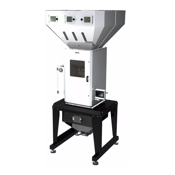
Installation and Debugging Read this chapter before installation. Install the machine according to following steps! Power supply of the machine should be connected by professional electricians! 3.1 Installation of SGB 3.1.1 Install SGB machine on a floor stand Picture 3-1: SGB-600-4 (Install SGB Machine on a Floor Stand) SGB can be installed on an optional mobile floor stand to be used with material storage bin and suction box (optional). -
Page 28: Sgb Install Sgb On A Molding Machine
3.1.2 SGB Install SGB on a Molding Machine Picture 3-2: Machine Mount Picture 3-3: Floor Mount 3.1.3 Installation of SGB Weighing pan SGB weighing pan is separated with the machine before delivery, which should be correctly mounted before the use of machine. 28(73) -
Page 29: Power Connection
Flexible block Fig. 3-4:SGB-40-4 Weighing pan Installation Diagram When the flexible block is adjusted to suitable angle, slide the weighing pan into the guiding rail groove, and then twist the block with fixation to prevent the weighing pan from slipping out. Groove Suspension loop Fig. -
Page 30: Compressed Air Supply
1) Make sure the voltage and frequency of the power source comply with those indicated on the manufacturer nameplate that attached to the machine. 2) Power cable and earth connection should conform to your local regulations. 3) Use independent electrical wires and power switch. Diameter of electrical wire should not be less than those used in the control box. - Page 31 Fig. 3-6:Feeding Installation Diagram(Optional with vacuum generator) Table 3-2:Feeding Installation Specification Name Description Central Vacuum Generator Gravimetric Blender European vacuum hopper receiver Installation Space When installing the machine, make sure the adequate installation space (at least 1m reserved around the machine). It is not good for machine operation, inspection and maintenance when installing in narrow space.
- Page 32 5) Parameters of specific collocation please refer to (Table 1-3: SVG Specification Table) 32(73)
-
Page 33: Application And Operation
Application and Operation SGB series gravimetric blender is manipulated through touch screen, which can rotate for convenient operation. Please obey the following rules while using it: 1) Don't use sharp objects (instead of hands) to touch the screen. And, screen should be prevented from fierce collision. - Page 34 System Initial Interface Operator Level Language Selection Feeding/Weighing Interface Operator level Feeding Monitoring Weighing Monitoring Weighing Data Viewing Interafce Interface Operartor Level Operator Level Operator Level Menu Selection Alarm Message Recipe Editing Interface Interface Interface Operator Level Operator Level Administrator Level Parameter Setting Passwords Weighing Calibration...
-
Page 35: About Keyboard Interface
4.3 About Keyboard Interface Touch the parameter input or setting area and a numerical or alphabetic numerical on-screen keyboard will come out to complete the man-machine conversation (parameter setting). Keyboard will automatically disappear after the input completes. 4.3.1 Input and Edit Alphabetic and Numerical Value Picture 4-3: Keyboard Interface Steps: User may input both numbers and hexadecimal values one character by another by... -
Page 36: Alternative Options
switch the switch to the keyboard symbol keyboard symbol switch switch to the keyboard number the numeric key right selection select to the right cancel all the numbers or characters at the left of the cancel cursor Note: If there is maximum/minimum limit, only values within the limits can be input. -
Page 37: Log In/Out
4.4 Log in/out 4.4.1 Administrator Log in User must use the log dialogue box to confirm operation limit when it is necessary to execute operations as administrator or repairman. Input user name and password in log dialogue box. Name Password Current user Picture 4-5: Administrator Log in Table 4-3:List of Administrator Login Screen... -
Page 38: Administrator Log Out
None level refueling In comparison with limits of authority of operator, it has authorities such as Administrator shini 3588 formula editing, parameter setting, level starting of manual mode and volume measuring mode and weight correction. In comparison with limits of authority of... - Page 39 Language selection keys: Select the operation language: English or Chinese, and English/Traditional Chinese then system will enter feeding/weighing interface. 39(73)
-
Page 40: Feeding/Weighing Selecting Interface
4.5.2 Feeding/Weighing Selecting Interface After selecting language under the initial interface, the system will display feeding/weighing selecting interface. Picture 4-7: Feeding/Weighing Selecting Interface Items Description Feed system key Enter the feeding monitoring interface. Weighing system key Enter the weighing monitoring interface. 4.5.3 Weighing Monitoring Interface (Taking four ingredients as example, and models of other ingredients are as the same). - Page 41 Items Description Display the current work condition Stop: denotes the machine is in stopping condition. Full hopper: denotes the blending hopper is full. Working condition Running: denotes machine is in automatically metering and discharging condition. Alarm: denotes system failure. Recipe document number Display the number of current recipe document.
-
Page 42: Weighing Data View Interface
4.5.4 Weighing Data View Interface Touch<screen switch>in weighing monitoring, the system will display the weighing date view interface. Picture 4-9: Weighing Data Display Interface 1 Picture 4-10: Weighing Data Display Interface 2 Items Description It displays batch number from the last accumulation Accomplished yield clearance to current time. -
Page 43: Recipe Setting Interface
ex-works setting) divided by time (unit: hour) is actual yield per hour. It displays the maximum yield within an hour. It is acquired through the calculation of both time and amount for Production rate processing with each batch, which changes according to different process time. -
Page 44: Recipe Elements
Save the recipe Save the data of recipe modification Cancel the recipe Cancel the recipe data Create new recipe Create new recipe Exit recipe editing Exit recipe editing Check Check the editing status 4.5.6 Recipe Elements Recipe includes the combination of related production data such as mixture proportion, etc. - Page 45 1.Recycled material 2.master-batch 3.Additive When the computation mode for master-batch and additives adopts No. 2 (percentage relative to raw material), it is able to select hopper 1 starved feeding alarm mode by setting from 0 to 1 with the following definition: 0:Sound an alarm and stop the machine Hopper starved...
-
Page 46: Menu Interface
batch of mixture might exceed the volume of the weight pan and the mixture might overflow. At that time, the batch size should be reduced. Set the discharging time of the mixture from the Weight pan weight pan after gravimetry within each period. discharging time Set a suitable time in which the material can [second]... -
Page 47: Parameter Setting Interface
Items Description Parameter setting button Press this button to enter parameter setting menu. Units setting button Press it to enter unit setting interface. Manual mode key Press it once to enter manual mode interface. User password key Press it once to enter user management interface. Display setting button Press it to enter display setting button. - Page 48 Picture 4-15: IP Setting Interface Picture 4-16: Weightlessness Parameter Interface Items Description Three ways are available: direct installing, installing with floor stand and lost-in-weight installing. Direct installing: start/stop based on high material level signal of mixing hopper. Assembly mode With floor stand: feed material twice into mixing hopper and discharge than to storage hopper, whose high material level control start/stop.
-
Page 49: Calibration Interface
Factory setting is 100g. Set the delayed batch unloading of mixing hopper to make the first Mixing frequency batch Volumetric metering frequency under Under mixing metering mode, the times of volumetric metering. mixing metering mode IP setting Press it to enter IP setting interface. Press it to enter lost-in-weight (when choosing the lost-in-weight hopper Weightlessness assembly) parameter setting interface. -
Page 50: User Management Interface
1) Press full-scale calibration to enter the process, then hang the accessory weight under the weighting pan and input the weight to the system and at last, press calibration to automatically enter the next step. 2) Take down the weight and stabilize the weight pan, then press set zero to finish the calibration process. -
Page 51: Manual Mode Interface
Note: It is important to write down the new user name and passwords when modifying a user. If you can’t remember you user name and passwords, please contact SHINI customer service center. 4.5.11 Manual Mode Interface Under menu selection interface, touch the <manual mode> to enter manual mode interface. - Page 52 Test the alarm and Press Buzzer test to test the alarm and the buzzer which are installed buzzer on the electrical cabinet door. Notice: Make sure all the components work normally. 52(73)
-
Page 53: Unit Parameter Setting Interface
4.5.12 Unit Parameter Setting Interface Under menu setting interface, touch <unit setting> to enter unit setting interface. Unit parameters are set in the manufacturer and need no adjustment except when replacing a PLC controller. Note: Random change of the parameter set in unit is prohibited. Otherwise, it will damage the machine! Picture 4-20: Unit Parameter Setting Interface Item... -
Page 54: Alarm Message Interface
4.5.13 Alarm Message Interface Touch Alarm Message and enter alarm message interface under which the faults information can be viewed and the faults can be removed in time. Picture 4-21: Alarm Message Interface Table 4-7:List of Alarm Checking Screen Item Description When the system fails, the content of corresponding fault Alarm information... -
Page 55: Control Of Feeding
4.5.14 Control of Feeding Before operating the control of automatic conveying, please connect the circuit part well by following the operation instruction and electrical control in this manual. Picture 4-22: Selection Screen of Feeding System and Weight System 1. Enter into the selection screen of feeding system and weight system. Then press<... -
Page 56: Level Sensor
Picture 4-24: Feeding Parameters Screen 3. Go back to the feeding monitoring screen after finishing setting of feeding parameters of hopper 1 to hopper 4. Then press the feeding switch to make the system automatically complete the material suction cycle (No need to open hoppers which are not used.). -
Page 57: Functions Of Each Level Switch
Fig. 4-26:Level Sensor Adjustment Table 4-9: List of Level Sensor Adjustment Item Description When the material level reaches or is higher than the material level sensor, observe the indicator at the end of the level sensor, [OFF] programming key which should be on normally. If it is off, it means the sensor hasn’t been adjusted well. - Page 58 material, and the raw material (hopper 1) shall take place of it automatically when the recycled material level is lower than this switch position. 3) When the recycled material level exceeds the position of switch again, hopper 2 recovers to unload the material. Picture 4-27: Level Switch on Hopper 2) Level switch on Mixing Tank It functions as inspecting the material level of mixing tank.
-
Page 59: Components Instructions
Picture 4-29: Level Switch on storage Tank 4.7 Components Instructions Attention! For application on the spot varies with the circumstances, new SGB allows each hopper freely defines its components categories. To operate the machine correctly, please read through this chapter carefully. 1. - Page 60 2.Raw material Definition: natural plastic particles without any additives in it. Distribution principle: percentage relative to the total weight of raw material (percentage between materials.) Description: hopper 1 is defined as raw material feeding and its percentage is automatically calculated. Total percentages of all the materials added together should be 100%.
- Page 61 Distribution Principle: percentage relative to the total weight of all the materials. For example when hopper 4 is defined as 5% additives, calculation will be as below according to the above-mentioned example: Hopper 2 (regrinds) =1000g × 25% =250g; The total weight of raw material and additives = (batch weight- regrinds weight) = (1000g-250g) =750g Hopper 1 (raw material) = (750g/105%) ×...
-
Page 62: Calculation Method Of Master-Batch And Additives
4.8 Calculation Method of Master-batch and additives There are three methods to calculate master-batch and additives: 1、Relative to batch capacity; Ratios of master-batch and additive are calculated relative to batch capacity. E.g.: BATCH=1.0Kg, Hopper 1=AUTO calculated, Hopper 2=40%, Hopper 3=3%, Hopper 4=2%. Thus real weights are: Hopper 1=1.0 ×... -
Page 63: Appendix 4: Chromatic Aberration Compensation Of Reclaimed Material
Hopper 3=(0.6+0.4) × 3%=0.03Kg(30g) Hopper 4=(0.6+0.4) × 2%=0.02Kg(20g) 4.8.1 Appendix 4: Chromatic Aberration Compensation of Reclaimed Material In some occasions, the color of reclaimed material may fade. Therefore, it is necessary to add master-batch. E.g.: reclaimed material=600g, raw material=1400g, proportion of master-batch=4% If the compensation value of reclaimed material is 0: Master-batch=raw material ×... -
Page 64: Control Mode
4.9 Control Mode There are three modes of metering controlling: Table 4-10:List of Metering Control Mode Item Description Weighing metering Each ingredient can be proportioned by metering the weighting mode sensor (normal mode is recommended). Volume (time) metering Each ingredient can be proportioned by time setting (When the mode weighing sensor fails, start the emergency standby mode). -
Page 65: Mixing Metering Mode
system failing to work or other special situations. Below is the principle: 1. First step, metering cell of reclaims conducts volumetric metering based on time setting of the current mode; 2. Second step, metering cell of raw material conducts volumetric metering based on time setting of the current mode;... -
Page 66: Trouble-Shooting
Trouble-shooting SGB-40~600 Alarm Results Possible reasons Solutions information 1. No material inside the hopper. Hoppers1~4 low 1. Add material into hopper. Alarm 2. Level sensor wasn't adjusted level 2. Adjust the sensitivity of sensor. properly. 1. No material in the hopper. 1. - Page 67 1. Check whether the safety door is closed Alarm and Safety door / low Safety door isn't closed or the tightly. stop the pressure pressure isn't enough. 2. Check whether the air pressure is machine enough. Alarm and The red light of load cell SF is 1.
- Page 68 can’t fit small proportion. 5. First startup, it is a normal situation. 1. Check if there is heavy object in pan. Off line of Alarm of Off line of weighing gauge or 2. Check the sensor. weighing sensor machine halt over pressure.
-
Page 69: Maintenance And Repair
Maintenance and Repair 6.1 Maintenance All the repair work should be done qualified personnel to prevent personal injuries and damage of the machine. 69(73) -
Page 70: Filter & Pressure Regulating Valve
6.2 Filter & Pressure Regulating Valve 6.2.1 Filter & Pressure Regulating Valve Drawing Parts list: 1. Pressure adjusting knob 2. Pressure gauge 3. Cup 4. Water outlet Picture 6-1: Filter & Pressure Regulating Valve Drawing 6.2.2 Filter & Pressure Regulating Valve Operation steps 1) Switch on the air source. -
Page 71: Clean Mixing Chamber
Picture 6-2: Drawing of Scale Pan Cleaning 6.5 Clean Mixing Chamber Open the door of the machine and clean the inside with an air gun. Picture 6-3: Clean Mixing Chamber 6.6 Magnetic Base Cleaning 1) Unscrew the cover of the discharging tube. 2) Unscrew the screw;... -
Page 72: Clean Material Shut-Off Plate
6.7 Clean Material Shut-off Plate In order not to obstruct material discharging, please clean machine base and material shut-off plate of it regularly. Picture 6: Clean Material Shut-off Plate 72(73) -
Page 73: Maintenance Schedule
6.8 Maintenance Schedule 6.8.1 About the Machine Model Manufacture date Voltage Ф Frequency Power 6.8.2 Check after Installation Check the pressure of air supply Check that door security switch is tightly fixed Check if machine base is firmly locked or not Electrical installation Voltage: Fuse melt current: 1 Phase...
Need help?
Do you have a question about the SGB Series and is the answer not in the manual?
Questions and answers