Table of Contents
Advertisement
Quick Links
Advertisement
Table of Contents

Related Manuals for videomed Truelink 4

Summary of Contents for videomed Truelink 4
- Page 1 Service Manual Truelink 4 Video Management System ENGLISH en-US...
- Page 2 This page is intentionally blank.
- Page 3 Fax: +39 0434 030689 surgical@hillrom.com hillrom.com VIDEOMED S.r.l. is a company of the Hill-Rom Holdings Group. The manufacturer is hereinafter referred to as VIDEOMED. Technical Customer Service The contact details for the current Technical Customer Service hubs in the individual countries are listed on the Internet at www.hillrom.com.
- Page 4 Truelink 4 VIDEOMED S.r.l. declines any liability for improper use of the system and/or for damage caused as a result of operations not covered by the technical documentation. 80028124_030_A – 773701 – 2021-04-29...
- Page 5 NOTICE The signal word indicates a dangerous situation that may lead to material damage or damage to the environment if no precautionary measures are taken. © 2021 VIDEOMED S.r.l. 80028124_030_A – 773701 – 2021-04-29...
- Page 6 Truelink 4 This page is intentionally blank. 80028124_030_A – 773701 – 2021-04-29...
-
Page 7: Table Of Contents
Truelink 4 unit connection diagram ........ - Page 8 Connect the monitors to Truelink 4........
-
Page 9: System Identification
System identification Warranty The complete warranty clauses are provided in the sales contract. VIDEOMED S.r.l. assures the safety and functional reliability of the system provided that: – the system is used, managed and repaired exclusively as described in this service manual;... -
Page 10: General Preliminary Information
General preliminary information General preliminary information Purpose of the document This document must be used to safely install the Truelink 4 Video Management System. Follow this service manual. Recipients of the service manual The installation manual of the Truelink 4 Video Management System is intended for trained technicians who are authorized to install it. -
Page 11: Personnel Qualifications
Consult the following table in order to establish the personnel skills and qualifications: Qualification Description Installation Technician Natural person authorized to install the Truelink 4 Video Management System. Symbols used in the manual and/or on the devices Symbol Description Symbol used to indicate the need to consult the instructions for use before using the equipment. - Page 12 General preliminary information Symbol Description Symbol used to indicate a medical device. Indicates the Unique Device Identification UDI code, is composed of UDI-DI (01) and UDI-PI ((11) date of production (21) serial number). The content of the package is fragile and is therefore to be treated with care.
-
Page 13: Terminology Used In The Manual
Image archiving and communication system Radiology Information System Rack Support used to accommodate the individual operating modules of the system Video clip Video sequence Wide Area Network Local Area Network Truelink 4 Table Control Module Trumpf Light Control 80028124_030_A – 773701 – 2021-04-29... -
Page 14: Safety Information
Safety information Safety information General safety warnings The Truelink 4 Video Management System must be installed by Installer Technicians adequately trained and authorized by VIDEOMED S.r.l. DANGER ELECTRIC SHOCK FROM DAMAGED MAINS POWER CABLE! Check the mains power cable before connecting it and do not use it if it has been crushed or if the insulation is damaged. -
Page 15: Combination With Other Medical Devices
Truelink 4 system. Combination with other medical devices The Truelink 4 Video Management System can be combined with medical devices from other manufacturers. Only install medical devices approved in accordance with standard IEC 60601-1. -
Page 16: Preventive Maintenance And Unscheduled Cleaning
Inform the operator of any defects. To perform maintenance on the Truelink 4 system and clean it, refer to the checklists (see Annex I of this manual). 80028124_030_A – 773701 – 2021-04-29... -
Page 17: General Installation Information
– List of material for Truelink 4; – Cabling plan; – Truelink 4 installation report, see annex I of this manual; – IEC 60364-7-710 or relevant national regulations. The cabling is positioned by the Installation Technician authorized by VIDEOMED S.r.l. -
Page 18: Cabling
Cabling Cabling The cables to be used for connecting the components of the Truelink 4 Video Management System are provided by VIDEOMED S.r.l. NOTICE Only use cables and connectors supplied by VIDEOMED S.r.l. Standard cabling The standard cabling is provided with:... -
Page 19: Types Of Analogue Signal
– 720 × 480 @ 29.97Hz = 480i Signal type Analogue Truelink 4 cable 1 × RG-6 / Coaxial Conversion Truelink 4 None Use with Truelink 4 – Best type of signal input for SD signal input RCA connector (Cinch) BNC connector BNC adapter RCA adapter 5.2.1.2... -
Page 20: S-Video - Separate Video
Truelink 4 cable 1 × RG-6 / Coaxial (after conversion) Conversion Truelink 4 From S-video to CVBS by using an adapter Use with Truelink 4 – Adapter available – It can be used as a standard CVBS signal 2 x BNC connector 1 x DIN / S-Video connector + female connector 5.2.1.4... -
Page 21: Types Of Digital Signal
1 × RG-6 / Coaxial Conversion Truelink 4 – SD-SDI (PAL/SECAM/NTSC) not natively supported by Truelink 4. In this case, conversion to a supported format via a converter is required. – No conversion required for high-definition formats HD-SDI and 3G-SDI Use with Truelink 4 –... -
Page 22: Dvi - Digital Visual Interface
– Best choice of use for Truelink 4 – Maximum resolution supported: 1920 × 1080 – All Truelink 4 DVI connectors are DVI-I (Dual Link) connectors to maximize compatibility. However, only digital data is used to transfer and display video signals. -
Page 23: Dp - Display Port
Use with Truelink 4 – Maximum resolution supported: 1920 × 1080 Preparing the cabling The cabling for the Truelink 4 Video Management System is carried out by using the following cables: – Cat 7 cable S/FTP 23 AWGX4, with RJ45 connector;... -
Page 24: Cabling Plan - Order Specifications
The “cabling plan - order specifications” is an overview of the installation diagram. The diagram shows the connections between the Truelink 4 system, its sources and destinations, specifying their location and type. The related cable connection plan describes, once again, all the conductors and their destinations. -
Page 25: Installing Empty Ducts
The cable length has a significant impact on the quality and performance of the entire system. Contact VIDEOMED S.r.l. to find a suitable technical solution. INSTALLING THE CABLES Make sure there is enough clearance when installing the cable. -
Page 26: Crimp Connectors Rj45 To Cat 7 Cables
Cabling 5.3.4 Crimp connectors RJ45 to CAT 7 cables Before crimping the RJ45 connectors to the CAT 7 cables, make sure you: – are using the right cable; – have a crimping clamp. Proceed as described below: Step Image Proceed by stripping the end of the cable, removing the outer sheath protecting the wires inside. - Page 27 Cabling Step Image Position the end of the connector in such a way that it contains the plugs. Use a clamp to crimp the CAT 6 AWG 26 cables. 80028124_030_A – 773701 – 2021-04-29...
-
Page 28: Crimping Coaxial Cables Rg-58 / Rg-6
Cabling 5.3.5 Crimping coaxial cables RG-58 / RG-6 Before crimping coaxial cables RG-58 and RG-6, make sure you: – are using the right cable; – have a crimping clamp. Proceed as follows: Step Image Proceed by stripping the end of the cable, removing the outer sheath protecting the wires inside. -
Page 29: Components Connection Diagram
Cabling Components connection diagram POWER 2 x RG58 ANTENNAS CABLES CAT7 to the OR CAT7 internal USB A -B RADIO MIC RX RG58 Audio cable 180EPoE Ac ve Op cal Fiber EXT. USB TX EXT. USB TX MINI PC - WORKSTATION 3,5mm jack RJ45 MIC input... -
Page 30: Truelink 4 Unit Connection Diagram
Conference unit. All units installed inside the Truelink 4 RACK must be connected to each other to make the most of all the benefits of Truelink 4 Video Management System. Here below is a table explaining the module cabling:... - Page 31 Cabling Truelink 4 units connection diagram: TL4 Videoconference Unit 2 x cable 2x cable HDMI 0,5m Audio Stereo VISCA Control ‘ON-AIR’ plate RJ45 cable – junction RoomCam Cable DVI-HDMI 180E RJ-45 patch CAT6 sftp w/o-o +12V Touchscreen w/b-b -12V video output...
-
Page 32: Components Installation
Components installation Components installation Follow the indications in chapter 5 “Cabling” to connect the modules. Hardware installation 6.1.1 Rack unit The dimension of the rack are length 800 mm, width 600 mm and height 757 mm with a weight 64 kg. ADJUSTABLE FOOT HEIGHT Holes for cable routing, see chapter 5 “Cabling”... - Page 33 Components installation Rack elements Image Junction box, with three terminal blocks inside (L,N,PE) Principal switch, when the switch is on “I” (green light on) operating voltage is turned on. Medical transformer isolator Metal panel with two fans 80028124_030_A – 773701 – 2021-04-29...
-
Page 34: System Power Supply
System power supply The image below provides information to the final customer on how to prepare the connection between the customer's power grid and the Truelink 4. NOTICE DEDICATED MAIN SAFETY SWITCH! It have to be placed close to the rack. -
Page 35: Rack Position
Components installation 6.1.3 Rack position The rack must be installed on a flat surface with enough room to 100 cm open the door. Access to the back of the rack must be guaranteed during installation. If this cannot be ensured, provide for an area that is large enough to allow for lateral access. -
Page 36: Assembling The Vesa Support System
Components installation Assembling the VESA support system 6.3.1 Removing the stand (if present) The touch screen can be placed on its own stand on a flat and steady surface or installed on a support arm. Remove the pedestal if the touch screen is installed on a support arm. Proceed as follows to remove the stand: Step Image... - Page 37 Components installation Proceed as follows if using an optional cover: Step Image Undo the 2 screws [4] of cover [3] of optional cover [5]. Position optional cover [5] on touch screen [1]. Take 4 screws to fix the touch screen from the accessories for the VESA support arm.
-
Page 38: Assembling The Touch Screen
Components installation 6.3.3 Assembling the touch screen Proceed as follows to assemble the touch screen: Step Image Slide touch screen [1] by keeping opening [9] in the lower part of cover [3] on handle [8] and push upwards. Place 2 fixing screws [2] in projecting parts [10] and [11] of VESA adapter plate [7] and tighten them. - Page 39 – pair of USB extenders or active USB extension cable NOTICE The DVI cable to the receiver and the Truelink 4 cable to the touch screen cable must be bent in the same way (TIA-568B). Using the pair of USB extenders or the active...
-
Page 40: Connecting The Monitors
Components installation Connecting the monitors Refer to the installation manual of the support arms for instructions on how to connect the cables. 6.4.1 Preliminary steps to assemble the monitor Remove the monitor cover before installing the monitor itself. Proceed as follows to assemble the monitor: Step Image Position monitor [2] facing down on a soft... -
Page 41: Assembling The Monitor
Components installation Assembling the monitor Proceed as follows to assemble the monitor: Step Image Slide monitor [2], so that opening [12] is at the base of cover [7] and push the monitor upwards. Position and then fix the 2 fixing screws [8] in the relevant housings [13] on the plate of VESA adapter [10]. - Page 42 Components installation Step Image Install the power supply unit in the false ceiling. Move up the power cables by using the monitor support arm and connect the device’s plug. Create a cable passage in the monitor arm cover. Connect the DVI output of the 180 P device [1] to the DVI input of the touchscreen inside the cover [7].
-
Page 43: Assembling The Room Cam
Components installation Assembling the Room Cam Proceed as follows to assemble the Room Cam: Step Image Use 4 screws to secure fixing frame [2] of Room Cam [8] to the ceiling or to the wall based on the information contained in the technical data. - Page 44 180 E Poe adapter [5] to the DVI VIDEO OUT connection. power Ctrl to Truelink 4 system rack Make sure Room Cam [8] is connected and then turn it on. Proceed as follows to assemble the Room Cam: Step...
- Page 45 Components installation Step Image Once the holes are made, place the Counterplate on its original position and let the cables come out from the hole [2]: power – the cat7 cable for the video supply signal, – the Visca adapter, –...
- Page 46 Components installation Step Image Place the cables cover and screw it to the Special Counterplate using the long screw supplied with the kit. 80028124_030_A – 773701 – 2021-04-29...
-
Page 47: Assembling The "On Air" Lamp
Components installation Assembling the “On Air” lamp Proceed as follows to assemble the lamp: Step Image Remove the ceiling panel 15 cm where On Air lamp will be installed. Make 3 holes aligned and wall side approx 15 cm from the wall edge. -
Page 48: On / Off Button Wiring
ON AIR Connect power to the cable connected to the Truelink 4 Main Unit on the On-Air port following the diagram on the ON AIR ctrl port side. -
Page 49: Installing The Ceiling Speakers
Components installation Installing the ceiling speakers Due to their weight, the false ceiling may need to be reinforced with the supplied frame in the area where the speaker will be installed. 6.9.1 Installing the speakers Proceed as follows to assemble the speaker: Step Image Use the drilling template supplied to mark the... - Page 50 Components installation Step Image Slightly loosen cable clamp [4] of ceiling speakers, push audio cable [6] through the cable clamp and ensure it comes out. Use the screws to connect audio cable [6] to connector [3] and reinsert the connector on counter-support [5].
- Page 51 Components installation Step Image Tighten the 2 fixing screws [8] until speakers press against the ceiling or against the reinforcement frame. Position cover [9]. 80028124_030_A – 773701 – 2021-04-29...
-
Page 52: Installing The Microphone Receiver
Components installation 6.10 Installing the microphone receiver Receiver [2] is installed in the rack with an optional installation set. Proceed as follows to install the receiver: Step Image Screw short bracket [1] on the left side and long bracket [3] on the right side of the receiver [2] with 3 self-threading screws [6]. -
Page 53: Assembling And Installing The Table Control Module (Tcm)
Components installation 6.11 Assembling and installing the Table Control Module (TCM) 6.11.1 Assembling the Table Control Module (TCM) Proceed as follows to assemble the TCM: Step Image Position the electronic circuit board on the base and make sure that the 3 holes for the fixing screws are in the right position, coinciding with the supports on the base, and that hole [A] is on the same side of the flat area... -
Page 54: Installing The Table Control Module (Tcm)
Components installation 6.11.2 Installing the Table Control Module (TCM) Proceed as follows to install the TCM: Step Image Define the final position of the TCM to create the right access for the cables. Side access: TCM positioned on / under a surface and the cable will come from the side (e.g. -
Page 55: Connecting The Table Control Module (Tcm)
Connecting the Table Control Module (TCM) Proceed as follows to connect the TCM: Step Image Connect the TCM to Truelink 4 with an SFTP or FTP cable ending with a RJ45 plug on both sides (TC1 cable). Connect the TCM to the emergency button with a 2x1 mm²... -
Page 56: Installing The Trumpf Light Control (Tlc)
6.12 Installing the Trumpf Light Control (TLC) The Trumpf Light Control (TLC) is a special feature of the Truelink 4 main unit that allows for control over the Trumpf Medical™ iLED™ 3, iLED 5, iLED 7 and TruLight™ surgical lights. -
Page 57: Connections
Proceed as follows to perform a digital connection: Connect a 180 E PoE adapter to the “DVI OUT” output. Insert a twisted pair cable (standard Truelink 4) into the 180 E PoE adapter and connect it to the “DVI IN” connector on the main unit. -
Page 58: Connect The Monitors To Truelink 4
Connect the microphone to one of the three ports in the microphone section of the Main module's audio port unit. NOTICE Only use the XLR-jack audio cable supplied by VIDEOMED S.r.l. to perform the connection. 80028124_030_A – 773701 – 2021-04-29... -
Page 59: Adjusting The Transmission Frequency
Internal / external cabling 7.1.4 Adjusting the transmission frequency When different Truelink 4 systems are used in a hospital, the set frequencies must be standardized in each operating room. However, the operating rooms have different frequencies to prevent interference and faulty transmissions. -
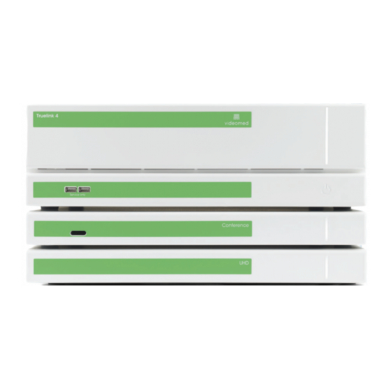
Page 60: Positioning The "Main" Unit
Internal / external cabling Positioning the “Main” unit The “Main” unit of the Truelink 4 Video Management System is positioned inside the Rack with, upon request, the two optional units called “Conference” and “UHD” or “UHD Plus”. Refer to the image below to position them. -
Page 61: Configuring Truelink 4
Access the configuration system directly from the GUI user interface. The Truelink 4 system will prompt you to enter a username and password. Contact VIDEOMED S.r.l. to request your login details. Proceed as follows to access the configuration system directly... -
Page 62: General Description Of The Configuration Interface
Configuring Truelink 4 General description of the configuration interface The configuration interface is structured as follows: Pos. Element Description MAIN MENU List of configurable sections. SECONDARY MENU Configuration area of the selected item on the main menu. ADVANCED MENU Area with advanced features. - Page 63 Configuring Truelink 4 Step Image Enter: – name of the new dedicated source (e.g.: DVI 1, SDI 1, etc). – type of input – special “Personality” source (optional) Press to confirm or to cancel the changes. Press to go to the Login screen.
-
Page 64: Graphical User Interface (Gui)
Configuring Truelink 4 8.1.1.1 Graphical User Interface (GUI) This subsection is used to activate the Graphical User Interface (GUI) option, which allows you to enter the user interface in the list of sources. Proceed as follows to activate the option:... -
Page 65: Options
Configuring Truelink 4 Step Image Press to confirm or to cancel the changes. Press the key (at the top of the menu bar) to save the changes made. Each monitor created within the list will be numbered and visible in the last position. -
Page 66: Units" Section
Truelink 4. REMOTE DEVICES Section where you can customize the configuration of the remote-controlled devices connected to the Truelink 4 system. The details of each section are reported in the following pages. 80028124_030_A – 773701 – 2021-04-29... -
Page 67: General
Element GENERAL GENERAL - Touchless link (connection to the Therapixel Fluid system) GENERAL - Videomed Boards settings (advanced settings of the digital video matrix built into Truelink 4) The details of each section are reported in the following pages. 80028124_030_A – 773701 – 2021-04-29... - Page 68 (at the top of the menu bar) to save the changes made. The Hospital/Structure name field is used to customize the name of the hospital where the Truelink 4 Video Management System is installed. Proceed as follows to edit the field: Step Image Enter the name of the hospital.
- Page 69 Configuring Truelink 4 The User Interface Locale field is used to set the language employed to view the graphic interface of the Truelink 4 Video Management System. Proceed as follows to edit the field: Step Image Select the desired language to view the system.
- Page 70 Configuring Truelink 4 The Date and Time field is used to customize the date and time formats used in the different sections of the Truelink 4 Video Management System. Proceed as follows to edit the field: Step Image Select to change the date and time.
- Page 71 Configuring Truelink 4 The PIN Lock field is used to set/change the pin to access the features of the Truelink 4 Video Management System. Proceed as follows to edit the field: Step Image Press the Pin Lock editable field. This opens the configuration window.
- Page 72 Configuring Truelink 4 Step Image With the Pin Lock feature enabled, press to enable the monitor lock feature upon system startup. After editing the Pin Lock settings, press confirm the changes. Press the key (at the top of the menu bar) to save the changes made.
- Page 73 Configuring Truelink 4 GENERAL section - Touchless link In this subsection it is possible to configure the parameters to synchronize Truelink 4 with Therapixel Fluid. Proceed as follows to edit the field: Step Image Select to edit the IP address the touchless system is associated with.
- Page 74 GENERAL section - Videomed Boards settings This sub-section provides access to the advanced customization of parameters of the digital matrix built into Truelink 4. The “Scalers” option is used to customize the conversion parameters for the video channels processed by the system.
- Page 75 Configuring Truelink 4 Step Image Press the key (at the top of the menu bar) to save the changes made. The Static Routes is used to set a static connection between a specific input and a specific output of the digital matrix.
- Page 76 Configuring Truelink 4 The Fullscreen Mode field is used to enable/disable the full screen feature of the input signals on the control touchscreen. Proceed as follows to edit the field: Step Image Press to enable/disable the full screen feature. Press the...
-
Page 77: Audio
Configuring Truelink 4 8.1.3.2 Audio The Audio subsection is used to change the configuration settings of the audio ports of the Truelink 4 Video Management System. Proceed as follows to edit the field: Step Image Change the volume level after exiting the “mute”... - Page 78 Configuring Truelink 4 The Tracks Configurator field is used to change the audio inputs of the Truelink 4 Video Management System. Proceed as follows to edit the field: Step Image The Tracks Configurator editable field. This opens the configuration window.
-
Page 79: Recording
8.1.3.3 Recording The Recording subsection is used to configure the recording features of the Truelink 4 Video Management System. Proceed as follows to edit the field: Step Image Press to enable or disable the Recording feature. - Page 80 Configuring Truelink 4 Step Image Press the key (at the top of the menu bar) to save the changes made. The Time-shift field is used to enable/disable the automatic buffering feature of the recording channels. Proceed as follows to edit the field:...
- Page 81 Configuring Truelink 4 Step Image Press the key (at the top of the menu bar) to save the changes made. RECORDING section - Add destination In this Add destination subsection, you can access the settings to create a new export destination.
- Page 82 Configuring Truelink 4 Step Image Press to confirm or to cancel the changes. Press the key (at the top of the menu bar) to save the changes made. 80028124_030_A – 773701 – 2021-04-29...
- Page 83 Configuring Truelink 4 The Patient ID Settings section is used to customize the management of patients in the Truelink 4 Video Management System. Proceed as follows to edit the section: Step Image Press the Patient ID editable field. This opens the configuration window.
-
Page 84: Hardware Streaming
Configuring Truelink 4 8.1.3.4 Hardware Streaming The Hardware Streaming subsection is used to enable/disable the Streaming features of the Truelink 4 Video Management System. Proceed as follows to edit the field: Step Image Press to enable or disable the Hardware Streaming feature. - Page 85 Configuring Truelink 4 Step Image Tick off the box to configure the streamer with the automatic network settings obtained via the DHCP. Alternatively, fill in all the fields for the configuration of the streamer's network parameters. Press the Open web interface editable field.
-
Page 86: Videoconference
Configuring Truelink 4 8.1.3.5 Videoconference The Video Conference subsection is used to enable/disable the video conference features of the Truelink 4 Video Management System. Proceed as follows to edit the field: Step Image Press to enable/disable the Video Conference feature. - Page 87 Configuring Truelink 4 Step Image Press the editable field to select the maximum number of recent calls to be displayed. Press the Clear list field to delete the list of calls. Press the key (at the top of the menu bar) to save the changes made.
- Page 88 Configuring Truelink 4 VIDEO CONFERENCE section - Add contact In the Add contact subsection you can access the settings to create a new contact to add to your contacts. Proceed as follows to edit the section: Step Image Press to add a new contact.
-
Page 89: Surgical Lights
8.1.3.6 Surgical Lights The Surgical Lights subsection is used to enable/disable the configuration options of the lamps placed in the operating room controlled by the Truelink 4 Video Management System. Proceed as follows to edit the field: Step Image Press to enable or disable the Surgical Lights feature. -
Page 90: Or Tables
OR Tables The OR Tables subsection is used to enable/disable the configuration options of the settings for the control of the operating table built into in the Truelink 4 Video Management System. Proceed as follows to edit the field: Step... -
Page 91: Remote Devices
Configuring Truelink 4 8.1.3.8 Remote Devices The Remote Device subsection is used to enable/disable the configuration options of the settings of the remotecontrolled devices connected to the Truelink 4 Video Management System. Proceed as follows to edit the field: Step Image Press to enable or disable the Remote Devices feature. - Page 92 Configuring Truelink 4 REMOTE DEVICES section - Operamed Touch Panel Connection Settings In the Operamed Touch Panel Connection Settings subsection you can access the connection settings for the remote control of the Operamed TCP (only if present). Proceed as follows to edit the section:...
- Page 93 Configuring Truelink 4 Step Image Press to confirm or to cancel the changes. Press the key (at the top of the menu bar) to save the changes made. 80028124_030_A – 773701 – 2021-04-29...
-
Page 94: Backup & Restore" Section
“BACKUP & RESTORE” section The Backup & Restore section is used to save the settings in a single package and create backups after completing the setting of the Truelink 4 Video Management System. Proceed as follows to edit the section: Step... - Page 95 BACKUP & RESTORE section - Create New Backup In this Create New Backup subsection you can access the settings to create a new backup file for the settings of the Truelink 4 Video Management System. Proceed as follows to edit the section:...
-
Page 96: Licensing" Section
Configuring Truelink 4 8.1.5 “LICENSING” section The Licensing section is used to check the details of the installed license or add and enable a new license issued by VIDEOMED S.r.l. Proceed as follows to edit the section: Step Image Click the installed license name to view the details of the installed components. - Page 97 Configuring Truelink 4 LICENSING section - Install license In this Install license subsection you can access the settings for installation a new license inside the Truelink 4 Video Management System. Proceed as follows to edit the section: Step Image Insert a USB pen drive containing the new license to be installed.
-
Page 98: Advanced Menu
Configuring Truelink 4 8.1.6 Advanced menu The advanced menu is divided as follows: RESET IMPORT EXPORT* CREATE CUSTOMER SERVICE PACKAGE ABOUT LOGOUT * The export function is only available via browser. The details of each section are reported in the following pages. -
Page 99: Reset
Configuring Truelink 4 8.1.6.1 Reset The Reset feature is used to upload again the last settings saved in the configuration system. Proceed as follows to Reset: Step Image Press to upload the last settings saved again. 80028124_030_A – 773701 – 2021-04-29... -
Page 100: Import / Export
Configuring Truelink 4 8.1.6.2 Import / Export The Import / Export feature is used to import or export the configuration currently in use in the Truelink 4 Video Management System. Proceed as follows to perform Imports / Exports: Step Image... - Page 101 Configuring Truelink 4 Step Image Press to choose the file to import. This opens the resource management window. Press to export the settings created. The settings are exported to the “download” folder of the system. Use a USB pen drive to export them.
-
Page 102: Customer Service Package
The Customer Service Package (CSP) is used by the Technician to create a data package regarding the status of the Video System and send it to the service authorized of VIDEOMED S.r.l., if various malfunctions or bugs have been found, to have a complete diagnostic analysis of the settings carried out. -
Page 103: About
VIDEOMED S.r.l. 8.1.7 About The About feature is used to access the general information menus of the Truelink 4 Video Management System. Proceed as follows to go to the About feature: Step Image Press to go to the system information menu. - Page 104 Step Image Press to view the relevant information. VERSIONS: displays the versions of the components installed in the Truelink 4 Video Management System. Press to view the relevant information. SOFTWARE MODULES: displays the modules installed in the Truelink 4 Video Management System.
-
Page 105: Logout
Configuring Truelink 4 8.1.7.1 Logout The Logout feature lets the user disconnect from the Truelink 4 configuration system. Proceed as follows to Logout: Step Image Press to log out from the system. 80028124_030_A – 773701 – 2021-04-29... -
Page 106: Annex I - Installation Report
Annex I - Installation report Annex I - Installation report INSTALLATION REPORT Truelink 4 PROJECT LOCATION HOSPITAL DEPARTMENT ROOM N. Serial ITEM Model Number Rack Unit Single Isolation Tranformer Main Unit Conference Unit UHD Unit UHD + Unit Touchscreen 1 FSN 27"... - Page 107 1. Check the cabling between Main and the other units, if installed. 2. Check the connections of the signals coming from the OR by referring to the Cabling Plan provided by Videomed. 3. Make sure that each cable has been named.
- Page 108 1. Verify parts integrity, cleaning status and closure systems. 2. Verify presence of labels for rear connections, S/N and identification. POWER 1. Connect the power supply and switch ON the unit. Turn on Truelink 4 and verify the automatic start. INTERNAL AND EXTERNAL CONNECTIONS 1.
- Page 109 Annex I - Installation report CABLING PLAN Installation report rev. 00 23/03/2020 VDM 8602 pag. 4/6 80028124_030_A – 773701 – 2021-04-29...
- Page 110 Annex I - Installation report Remarks/Open topics INPUTS OUTPUTS PORT SIGNAL CABLE PORT SIGNAL CABLE DVI 1 DVI 1 DVI 2 DVI 2 DVI 3 DVI 3 DVI 4 DVI 4 DVI 5 DVI 5 DVI 6 DVI 6 DVI 7 DVI 7 DVI 8 DVI 8...
- Page 111 Annex I - Installation report FINAL APPROVAL ORIGINATED BY: ____ / ____ / _______ Signature APPROVED BY: ____ / ____ / _______ Signature CUSTOMER: ____ / ____ / _______ DEPARTMENT: Signature Installation report rev. 00 23/03/2020 VDM 8602 pag. 6/6 80028124_030_A –...
- Page 112 Annex I - Installation report This page is intentionally blank. 80028124_030_A – 773701 – 2021-04-29...
- Page 113 This page is intentionally blank.
- Page 114 80028124_030_A – 773701 – 2021-04-29...
Need help?
Do you have a question about the Truelink 4 and is the answer not in the manual?
Questions and answers