Table of Contents
Advertisement
Quick Links
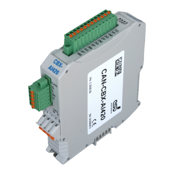
CAN-CBX-AI420
4 A/D-Converter-Inputs, 20 Bit
Manual
to Product C.3030.02
CAN-CBX-AI420
Page 1 of 103
Manual • Doc.-No.: C.3030.21 / Rev. 1.4
esd electronic system design gmbh
Vahrenwalder Str. 207 • 30165 Hannover • Germany
http://www.esd.eu
Phone: +49 (0) 511 3 72 98-0 • Fax: +49 (0) 511 3 72 98-68
Advertisement
Table of Contents

Summary of Contents for ESD CAN-CBX-AI420
- Page 1 CAN-CBX-AI420 Page 1 of 103 Manual • Doc.-No.: C.3030.21 / Rev. 1.4 esd electronic system design gmbh Vahrenwalder Str. 207 • 30165 Hannover • Germany http://www.esd.eu Phone: +49 (0) 511 3 72 98-0 • Fax: +49 (0) 511 3 72 98-68...
- Page 2 The information in this document has been carefully checked and is believed to be entirely reliable. esd makes no warranty of any kind with regard to the material in this document, and assumes no responsibility for any errors that may appear in this document. In particular descriptions and technical data specified in this document may not be constituted to be guaranteed product features in any legal sense.
- Page 3 Chapter moved and updated Chapter “Software” renamed to “CANopen-Firmware”, general part (chapter 7.1 - 7.4) updated and restructured Parameter description inserted Chapter to “Definition of Terms” inserted Product-specific Properties CAN-CBX-AI420 inserted in table, new objects 1005 , 100E 7.9.1 1019 , 1020...
- Page 4 The intended use of the CAN-CBX module is the operation as a CANopen module with analog outputs. The esd guarantee does not cover damages which result from improper use, usage not in accordance with regulations or disregard of safety instructions and warnings.
-
Page 5: Table Of Contents
5.2.1 General Rules ........... . 33 CAN-CBX-AI420 Page 5 of 103 Manual •... - Page 6 ) ........73 Page 6 of 103 CAN-CBX-AI420 Manual • Doc.-No.: C.3030.21 / Rev. 1.4...
- Page 7 10. Order Information ............102 CAN-CBX-AI420 Page 7 of 103 Manual •...
- Page 8 Number Representation All numbers in this document are base 10 unless designated otherwise. For hexadecimal numbers appended . For example, 42 is represented as 2A in hexadecimal format. Page 8 of 103 CAN-CBX-AI420 Manual • Doc.-No.: C.3030.21 / Rev. 1.4...
-
Page 9: Overview
Fig. 1: Block circuit diagram of the CAN-CBX-AI420 module The CAN-CBX-AI420 module is equipped with a MB90F497 microcontroller, which buffers the CAN data into a local SRAM. The firmware is stored in the flash. Parameters are stored in a serial EEPROM. -
Page 10: Technical Data
Plastic housing for carrier rail mounting NS35/7,5 DIN EN 60715 width: 22.5 mm, length: 99 mm, constructional height: 114.5 mm Dimensions (dimensions without mating connectors) Weight 140 g Table 1: General technical data of the module Page 10 of 103 CAN-CBX-AI420 Manual • Doc.-No.: C.3030.21 / Rev. 1.4... -
Page 11: Cpu-Unit
10 Kbit/s up to 1 Mbit/s Bustermination has to be set externally if required 5-pin connector with spring-cage connection or via CAN- Connection CBX-TBUS-connector (InRailBus) Table 3: Data of the CAN interface CAN-CBX-AI420 Page 11 of 103 Manual • Doc.-No.: C.3030.21 / Rev. 1.4... -
Page 12: Analog Inputs
The firmware of the module supports CANopen according to CiA CANopen specification CiA 301 [1] und CiA DS-401 [2]. The CAN-CBX-AI420 EDS file can be downloaded f rom the esd website www.esd.eu. Page 12 of 103 CAN-CBX-AI420 Manual • Doc.-No.: C.3030.21 / Rev. 1.4... -
Page 13: Hardware Installation
Hardware-Installation 3. Hardware Installation 3.1 Connecting Diagram Fig. 2: Connections of the CAN-CBX-AI420 module Note: The connector pin assignment can be found on page 24 and following. For conductor connection and conductor cross section see page 30. CAN-CBX-AI420 Page 13 of 103... -
Page 14: Led Display
Fig. 3: Position of the LEDs in the front panel The CAN-CBX-AI420 module is equipped with four status LEDs. The terms of the indicator states of the LEDs are chosen in accordance with the terms recommended by the CiA [3]. The indicator states of the LEDs are described in the following chapters. -
Page 15: Operation Of The Can-Error Led
Module is in bootloader mode, the power LED is off, 3 flashes (or coding switch position ID-node > 7F when switching on; see page 16) Table 7: Indicator states of the CANopen Status-LED CAN-CBX-AI420 Page 15 of 103 Manual • Doc.-No.: C.3030.21 / Rev. 1.4... -
Page 16: Operation Of The Error-Led
The coding switches for the Node-ID are set to an invalid ID-value, CAN-Error LED: on when switching on. The firmware application will be stopped. Table 10: Special Indicator States Page 16 of 103 CAN-CBX-AI420 Manual • Doc.-No.: C.3030.21 / Rev. 1.4... -
Page 17: Assignment Of Led Labelling To Name In Schematic Diagram
Hardware-Installation 3.2.7 Assignment of LED Labelling to Name in Schematic Diagram Labelling on Name of the LED in Schematic CAN-CBX-AI420 Diagram* LED200A LED200B LED200C LED200D The Schematic Diagram is not part of this manual. CAN-CBX-AI420 Page 17 of 103 Manual • Doc.-No.: C.3030.21 / Rev. 1.4... -
Page 18: Coding Switch
Setting the address range of the coding switches to values higher than 7F causes error messages, the red CAN-Error LED is on. If the coding switches are set to 00 , the CAN-CBX-module changes into Bootloader mode. Page 18 of 103 CAN-CBX-AI420 Manual • Doc.-No.: C.3030.21 / Rev. 1.4... -
Page 19: Setting The Baud Rate
83 3 , implemented since firmware version 2.02 Table 11: Index of the baud rate 3.3.3 Assignment of Coding-Switch Labelling to Name in Schematic Diagram Labelling on the Name in the Schematic CAN-CBX-AI420 Diagram * Baud SW301 SW300 High SW302 The Schematic Diagram is not part of this manual. -
Page 20: Installation Of The Module Using Inrailbus Connector
Swivel the CAN-CBX module onto the mounting rail in pressing the module downwards according to the arrow as shown in figure 6. The housing is mechanically guided by the DIN rail bus connector. Page 20 of 103 CAN-CBX-AI420 Manual • Doc.-No.: C.3030.21 / Rev. 1.4... -
Page 21: Connecting Power Supply And Can-Signals To Cbx-Inrailbus
Plug the terminal plug into the socket on the right of the mounting-rail bus connector of the InRailBus, as described in Fig. 8. Then connect the CAN interface and the power supply voltage via the terminal plug. CAN-CBX-AI420 Page 21 of 103 Manual • Doc.-No.: C.3030.21 / Rev. 1.4... -
Page 22: Connection Of The Power Supply Voltage
The functional earth contact is a current path of low impedance between circuits and earth, that is not intended as protection measure, but improves the stability. It is not a protection against accidental contact for persons. Page 22 of 103 CAN-CBX-AI420 Manual • Doc.-No.: C.3030.21 / Rev. 1.4... -
Page 23: Connection Of Can
Now the module is detached from the bottom edge of the mounting rail and can be removed. Note: It is possible to remove individual devices from the CBX station without interrupting the InRailBus connection, because the contact chain will not be disrupted. CAN-CBX-AI420 Page 23 of 103 Manual • Doc.-No.: C.3030.21 / Rev. 1.4... -
Page 24: Connector Assignments
Note: The pins 1 and 4 are connected internally. The pins 2 and 3 are connected internally. Signal Description: P24... power supply voltage +24 V M24... reference potential Page 24 of 103 CAN-CBX-AI420 Manual • Doc.-No.: C.3030.21 / Rev. 1.4... -
Page 25: Can
The CAN interface can be connected via the CAN connector or optionally via the InRailBus. Use the mounting-rail bus connector of the CBX-InRailBus (CAN-CBX-TBUS), see order information (page 102). CAN-CBX-AI420 Page 25 of 103 Manual • Doc.-No.: C.3030.21 / Rev. 1.4... -
Page 26: Can Connector (X400)
Recommendation of an adapter cable from 5-pin Combicon (here line connector FK-MCP1,5/5- STF-3,81 with spring-cage-connection) to 9-pin DSUB: T he 9-pin DSUB connector is assigned according to CiA 102 Page 26 of 103 CAN-CBX-AI420 Manual • Doc.-No.: C.3030.21 / Rev. 1.4... -
Page 27: Can And Power Supply Voltage Via Inrailbus Connector
CAN signals CAN_GND ... reference potential of the local CAN-Physical layers P24... power supply voltage +24 V M24... reference potential FE... functional earth contact (EMC)(connected to mounting rail potential) CAN-CBX-AI420 Page 27 of 103 Manual • Doc.-No.: C.3030.21 / Rev. 1.4... -
Page 28: Analog Inputs
Furthermore the resistors of both measuring lines of the differential analog inputs should be identical. Fig. 13: Principle of the internal circuit of the -converter The gain-error increases with increasing resistance R (see figure above). SOURCE Page 28 of 103 CAN-CBX-AI420 Manual • Doc.-No.: C.3030.21 / Rev. 1.4... -
Page 29: Analog Inputs X500
To achieve short conductor loops it is recommended to use an adjacent GND-Pin. Note: To ensure EMC properties a cable with a maximum wire length of 3 m has to be used for the analog inputs CAN-CBX-AI420 Page 29 of 103 Manual • Doc.-No.: C.3030.21 / Rev. 1.4... -
Page 30: Conductor Connection/Conductor Cross Sections
2 conductors with same cross section, stranded, 1 mm² n.a. TWIN ferrules with plastic sleeve, max. Minimum AWG according to UL/CUL Maximum AWG according to UL/CUL n.a..not allowed Page 30 of 103 CAN-CBX-AI420 Manual • Doc.-No.: C.3030.21 / Rev. 1.4... -
Page 31: Correct Wiring Of Electrically Isolated Can Networks
5.1.1 General Rules Note: esd grants the EU Conformity of the product, if the CAN wiring is carried out with at least single shielded single twisted pair cables that match the requirements of ISO 118982-2. Single shielded double twisted pair cable wiring as described in chapter 5.2 ensures the EU Conformity as well. -
Page 32: Cabling
If the used CAN interface is not equipped with an integrated CAN termination and it is at an end of the bus, use external termination plugs. 9-pin DSUB-termination connectors with male and female contacts and earth terminal are available as accessories Page 32 of 103 CAN-CBX-AI420 Manual • Doc.-No.: C.3030.21 / Rev. 1.4... -
Page 33: Heavy Industrial Environment (Double Twisted Pair Cable)
Select a working combination of bit rate and cable length. Keep away cables from disturbing sources. If this cannot be avoided, double shielded wires are recommended. Fig. 16: CAN wiring for heavy industrial environment CAN-CBX-AI420 Page 33 of 103 Manual • Doc.-No.: C.3030.21 / Rev. 1.4... -
Page 34: Device Cabling
DSUB9-connector from ERNI (ERBIC CAN BUS MAX, order no.:154039). The usage of esd’s T-connector type C.1311.03 is not recommended for single shielded double twisted pair cables because the shield potential of the conductive DSUB housing is not looped through this T-connector type. -
Page 35: Electrical Grounding
Optical couplers are delaying the CAN signals. By using fast digital isolators and testing each board at 1 Mbit/s, esd modules typically reach a wire length of 37 m at 1 Mbit/s within a closed net without impedance disturbances like e.g. longer stub. -
Page 36: Examples For Can Cables
Part No.: 93 022 026 (UL appr.) 74535 Mainhardt Germany BUS-Schleppflex-PUR-C (2x 2x 0.25 mm²) Part No.: 94 025 026 (UL appr.) www.concab.de Note: Completely configured CAN cables can be ordered from esd. Page 36 of 103 CAN-CBX-AI420 Manual • Doc.-No.: C.3030.21 / Rev. 1.4... -
Page 37: Can-Bus Troubleshooting Guide
- there are no open circuits in CAN_H or CAN_L wiring - your bus system has two terminating resistors (one at each end) and that they are 120 each. CAN-CBX-AI420 Page 37 of 103 Manual • Doc.-No.: C.3030.21 / Rev. 1.4... -
Page 38: Ground
3. Measure the DC voltage between CAN_H and GND (see figure above). 4. Measure the DC voltage between CAN_L and GND (see figure above). Normally the voltage should be between 2.0 V and 4.0 V. Page 38 of 103 CAN-CBX-AI420 Manual • Doc.-No.: C.3030.21 / Rev. 1.4... -
Page 39: Can Transceiver Resistance Test
Another sign for a faulty transceiver is a very high deviation between the two measured input resistance (>> 200%). Ω Ω Figure 20: Simplified diagram of a CAN node CAN-CBX-AI420 Page 39 of 103 Manual • Doc.-No.: C.3030.21 / Rev. 1.4... -
Page 40: Canopen Firmware
SDOs are used to transmit module internal configuration- and parameter data. In opposition to the PDOs SDO-messages are confirmed. A write or read request on a data object is always answered by a response telegram with an error index. Page 40 of 103 CAN-CBX-AI420 Manual • Doc.-No.: C.3030.21 / Rev. 1.4... -
Page 41: Nmt-Boot-Up
1000 ... 1FFF Communication Profile Area 2000 ... 5FFF Manufacturer Specific Profile Area 6000 ... 9FFF Standardized Device Profile Area A000 ... FFFF reserved CAN-CBX-AI420 Page 41 of 103 Manual • Doc.-No.: C.3030.21 / Rev. 1.4... -
Page 42: Communication Parameters Of The Pdos
Frequently required combinations are, for instance: = 64 : Read Request, i.e. a parameter is to be read = 35 : Write Request with 32-bit data, i.e. a parameter is to be set Page 42 of 103 CAN-CBX-AI420 Manual • Doc.-No.: C.3030.21 / Rev. 1.4... - Page 43 The least significant byte is always in ‘Data 1’. With 16-bit values the most significant byte (bits 8...15) is always in ‘Data 2’, and with 32-bit values the MSB (bits 24...31) is always in ‘Data 4’. CAN-CBX-AI420 Page 43 of 103...
- Page 44 08000022 device state 08000024 access to flash failed Page 44 of 103 CAN-CBX-AI420 Manual • Doc.-No.: C.3030.21 / Rev. 1.4...
-
Page 45: Overview Of Used Canopen-Identifiers
Sync to all, (configurable via object 1005 Emergency Message + NodeID configurable via object 1014 TPDO2 + NodeID PDO2 from CAN-CBX-AI420 (Tx) (object 1801 TPDO3 + NodeID PDO3 from CAN-CBX-AI420 (Tx) (object 1802 Client-SDO + Node-ID SDO from CAN-CBX-AI420 (Tx) -
Page 46: Default Pdo-Assignment
8 byte (Transmit-PDO) as 32-bit values from CAN-CBX-AI420 A/D-values channel 3 to 4 TPDO3 + Node-ID 8 byte (Transmit-PDO) as 32 bit values TPDO2 (CAN-CBX-AI420 ->) CAN-Identifier: 280 + Node-ID Byte Read_Analog_Input_32-Bit_1 Read_Analog_Input_32-Bit_2 Parameter TPDO3 (CAN-CBX-AI420 ->) CAN-Identifier: 380 + Node-ID... -
Page 47: Reading The Analog Values
• event controlled, asynchronous: The transmission is initiated if the state of selected inputs has changed (PDO-transmission type 254, 255). 7.7.2 Supported Transmission Types Based on DS-301 PDO-Transmission Transmission supported by synchro- asynchro- Type CAN-CBX-AI420 cyclic acyclic nous nous 1...240 241...251 reserved CAN-CBX-AI420 Page 47 of 103 Manual •... -
Page 48: Communication Profile Area
This parameter can be read or written. Value range value range of the parameter Default value default setting of the parameter Name/Description name and short description of the parameter Page 48 of 103 CAN-CBX-AI420 Manual • Doc.-No.: C.3030.21 / Rev. 1.4... -
Page 49: Implemented Canopen-Objects
1003 Pre-Defined-Error-Field unsigned32 1005 COB-ID-Sync unsigned32 1006 Communication Cycle Period unsigned 32 1008 Manufacturer Device Name visible string “CAN-CBX-AI420” x.yy 1009 Manufacturer Hardware Version visible string (depending on version) x.yy 100A Manufacturer Software Version visible string (depending on version) 100C... - Page 50 Description Data type index mode properties 1F80 NMT startup unsigned 32 default: 2 (autostart disabled) Self starting nodes timing 1F91 unsigned 16 default: 64 (= 100 ms) parameters Page 50 of 103 CAN-CBX-AI420 Manual • Doc.-No.: C.3030.21 / Rev. 1.4...
-
Page 51: Device Type (1000 )
The value of the device type of this CAN-CBX module is printed in chapter 7.9.1 (page 49) The data field is always structured following the rule ‘LSB first, MSB last‘ (see page 43, data field). CAN-CBX-AI420 Page 51 of 103... -
Page 52: Error Register (1001 )
For a list of the error bits supported by this CAN-CBX module see chapter 7.9.1 (page 49). Bits which are not supported are always returned as ‘0’. If an error is active, the according bit is set to ‘1’. Page 52 of 103 CAN-CBX-AI420 Manual • Doc.-No.: C.3030.21 / Rev. 1.4... -
Page 53: Pre-Defined Error Field (1003 )
- in order to delete the error list this variable has to be set to ‘0’ - if no_of_errors_in_list 0, the error register (Object 1001 ) is set CAN-CBX-AI420 Page 53 of 103 Manual • Doc.-No.: C.3030.21 / Rev. 1.4... - Page 54 Implemented CANopen Objects error-code x The 32-bit long error code consists of the CANopen-emergency error code described in [1] and the error code defined by esd (manufacturer-specific error field). Bit: 31 ..16 15 ..0 manufacturer-specific emergency-error-code...
-
Page 55: Cob-Id Of Sync-Message (1005 )
1: Device generates SYNC message always 0 (11-bit ID) 28...11 always 0 (29-bit IDs are not supported) 10...0 (LSB) Bit 0...10 of the SYNC-COB-ID The identifier can take values between 0...7FF CAN-CBX-AI420 Page 55 of 103 Manual • Doc.-No.: C.3030.21 / Rev. 1.4... -
Page 56: Communication Cycle Period (1006 )
Communication Cylcle Period Data type unsigned 32 Access mode Default value Value range of the parameter: Value Meaning No transmission of SYNC messages 1...FFFFFFFF Cycle time in microseconds Page 56 of 103 CAN-CBX-AI420 Manual • Doc.-No.: C.3030.21 / Rev. 1.4... -
Page 57: Manufacturer Device Name (1008 )
INDEX 1008 Name manufacturer device name Data type visible string Default value see chapter 7.9.1 (page 49) For detailed description of the SDO Uploads, please refer to [1]. CAN-CBX-AI420 Page 57 of 103 Manual • Doc.-No.: C.3030.21 / Rev. 1.4... -
Page 58: Manufacturer Hardware Version (1009 )
Reading the software version is similar to reading the manufacturer’s device name via the domain upload protocol. Please refer to [1] for a detailed description of the upload. Page 58 of 103 CAN-CBX-AI420 Manual • Doc.-No.: C.3030.21 / Rev. 1.4... -
Page 59: Guard Time (100C ) Und Life Time Factor
Default value 0 [ms] Minimum value Maximum value FFFF (65.535 s) INDEX 100D Name life time factor Data type unsigned 8 Access mode Default value Minimum value Maximum value CAN-CBX-AI420 Page 59 of 103 Manual • Doc.-No.: C.3030.21 / Rev. 1.4... -
Page 60: Node Guarding Identifier
Meaning 31 (MSB) reserved 29...11 always 0, because 29-bit-IDs are not supported 10...0 (LSB) bit 0...10 of the node guarding identifier The identifier can take values between 1...7FF Page 60 of 103 CAN-CBX-AI420 Manual • Doc.-No.: C.3030.21 / Rev. 1.4... -
Page 61: Store Parameters (1010 )
... 1029 save_application_parameter saves all application parameters of those objects (objekte 6000 ... 9FFF , if available), which have a read/write (rw) right of access (here e.g. 6xxx CAN-CBX-AI420 Page 61 of 103 Manual • Doc.-No.: C.3030.21 / Rev. 1.4... - Page 62 CAN-CBX module does not save the parameters on command CAN-CBX module saves the parameters on command Autonomous saving means that the CAN-CBX module stores the storable parameters non-volatile and without a user request. Page 62 of 103 CAN-CBX-AI420 Manual • Doc.-No.: C.3030.21 / Rev. 1.4...
-
Page 63: Restore Default Parameters (1011 )
(objekts 6000 ... 9FFF , if available, here e.g. 6xxx restore_manufacturer_parameter loads all manufacturer default parameters of those objects (objects 2000 ... 5FFF , if available, here e.g. 2xxx CAN-CBX-AI420 Page 63 of 103 Manual • Doc.-No.: C.3030.21 / Rev. 1.4... - Page 64 On read access to the appropriate sub-index, the CANopen device provides information about its default parameter restoring capability with the following format: Bit: Content: reserved Value Description the CAN-CBX-module does not restore default parameters the CAN-CBX-module restores the default parameters Page 64 of 103 CAN-CBX-AI420 Manual • Doc.-No.: C.3030.21 / Rev. 1.4...
-
Page 65: Cob_Id Emergency Message (1014 )
(always 0) always 0 (11-bit ID) 28...11 always 0 (29-bit IDs are not supported) 10...0 (LSB) bits 0...10 of COB-ID The identifier can take values between 0...7FF CAN-CBX-AI420 Page 65 of 103 Manual • Doc.-No.: C.3030.21 / Rev. 1.4... -
Page 66: Inhibit Time Emcy (1015 )
Value range 0...FFFF Default value The Inhibit Time for the EMCY message can be defined with this entry. The time is determined as a multiple of 100 s. Page 66 of 103 CAN-CBX-AI420 Manual • Doc.-No.: C.3030.21 / Rev. 1.4... -
Page 67: Consumer Heartbeat Time (1016 )
Each module can act as a heartbeat producer and a heartbeat consumer. The CAN-CBX module can represent at most one heartbeat consumer per CAN net. Access Index Sub-index Description Value range Default Data type mode number_of_entries unsigned 8 1016 consumer_heartbeat_time 0...007FFFFF unsigned 32 CAN-CBX-AI420 Page 67 of 103 Manual • Doc.-No.: C.3030.21 / Rev. 1.4... - Page 68 Example: consumer-heartbeat_time = 0031 03E8 => Node-ID = 31 = 49 => heartbeat time = 3E8 = 1000 => 1 s Page 68 of 103 CAN-CBX-AI420 Manual • Doc.-No.: C.3030.21 / Rev. 1.4...
-
Page 69: Producer Heartbeat Time (1017 )
Cycle time [ms] of heartbeat producer to transmit the heartbeat on the node-guarding ID (see object 100E The consumer-heartbeat time of the monitoring module must always be higher than the producer-heartbeat time of the heartbeat-transmitting module. CAN-CBX-AI420 Page 69 of 103 Manual • Doc.-No.: C.3030.21 / Rev. 1.4... -
Page 70: Identity Object (1018 )
0...FFFFFFFF unsigned 32 Description of the variables: vendor_id This variable contains the esd-vendor-ID. This is always 0000 0017 product_code Here the esd-article number of the product is stored. The nibbles of the long words have the following meaning: product_code = 1... - Page 71 If the value ‘C1C2 0105 ’ is being read, this corresponds to the hardware-serial number code ‘AB 0105’. This value has to correspond to the serial number of the module. CAN-CBX-AI420 Page 71 of 103 Manual • Doc.-No.: C.3030.21 / Rev. 1.4...
-
Page 72: Synchronous Counter Overflow Value (1019 )
The SYNC message shall be transmitted as a CAN message of data length ‘0’. reserved The SYNC message shall be transmitted as a CAN message of data length ‘1’. The 2...240 first data byte contains the counter. 241...255 reserved Page 72 of 103 CAN-CBX-AI420 Manual • Doc.-No.: C.3030.21 / Rev. 1.4... -
Page 73: Verify Configuration (1020 )
Date of the last configuration of the module. The value is defined in number of days since the 01.01.1984. configuration_time Time in ms since midnight at the day of the last configuration. CAN-CBX-AI420 Page 73 of 103 Manual • Doc.-No.: C.3030.21 / Rev. 1.4... -
Page 74: Error Behaviour Object (1029 )
Bus off The module can enter the following states if an error occurs. Variable Module state pre-operational (only if the current state is operational) no state change stopped Page 74 of 103 CAN-CBX-AI420 Manual • Doc.-No.: C.3030.21 / Rev. 1.4... -
Page 75: Nmt Startup
The value range of the object is described in the following table: Value Meaning Auto startup disabled 0000 0002 (default) 0000 0008 Auto startup enabled all other values reserved CAN-CBX-AI420 Page 75 of 103 Manual • Doc.-No.: C.3030.21 / Rev. 1.4... -
Page 76: Self Starting Nodes Timing Parameters (1F91 )
Sub-index 1 of this object contains the timeout in [ms] between the change from “preoperational” > “operational”. In default it is 100 ms. The sub-indices 2 and 3 of this object are not supported. Page 76 of 103 CAN-CBX-AI420 Manual • Doc.-No.: C.3030.21 / Rev. 1.4... -
Page 77: Object Transmit Pdo Communication Parameter 1801
0...FF unsigned 8 1802 inhibit time 0...FFFF unsigned 16 reserved 0..FF unsigned 8 const event timer 0...FFFF unsigned 16 The transmission types 0, 1...240 and 252...255 are supported. CAN-CBX-AI420 Page 77 of 103 Manual • Doc.-No.: C.3030.21 / Rev. 1.4... -
Page 78: Transmit Pdo Mapping Parameter 1A01
1A02 Read_Analog_Input_32_4 0...FFFF FFFF 6402 0420 unsigned 32 Note: The local firmware allows every TPDO-mapping, i.e. combinations of 16-bit- and 32- bit-A/D-values in one frame are also possible. Page 78 of 103 CAN-CBX-AI420 Manual • Doc.-No.: C.3030.21 / Rev. 1.4... -
Page 79: Device Profile Area
Analog Input Interrupt Lower Limit integer 32 6426 Analog Input Interrupt Delta Unsigned unsigned 32 7.10.2 Relationship Between the Implemented Objects for the Analog Inputs Example here: Module is in Operational state. CAN-CBX-AI420 Page 79 of 103 Manual • Doc.-No.: C.3030.21 / Rev. 1.4... -
Page 80: Read Input 16-Bit (6401 )
=> 10 V / 8000 => 0.3052 mV VARIABLE The calculation of the measured value corrected by offset, gain, averaging and if necessary addition is described from page 82 for Read_Analog_Input_32-Bit (6402 Page 80 of 103 CAN-CBX-AI420 Manual • Doc.-No.: C.3030.21 / Rev. 1.4... -
Page 81: Read Input 32-Bit (6402 )
=> 10,0 V / 8000 0000 => 4.6566 nV VARIABLE Note: 24-bit resolution of the A/D-converter: 1 LSB => 10 V / 80 0000 => 1.19209 V AD-CONVERTER CAN-CBX-AI420 Page 81 of 103 Manual • Doc.-No.: C.3030.21 / Rev. 1.4... - Page 82 2. Addition of the measured values: Ana_In_32_accu_x = Ana_In_32_og_x + Ana_In_32_og_x + ... + Ana_In_32_og_x 3. Calculation of the moving average: Ana_In_32_accu_x + Ana_In_32_accu_x + ... + Ana_In_32_accu_x Read_Analog_Input_32_x = ------------------------------------------------------------------------------------------------- Page 82 of 103 CAN-CBX-AI420 Manual • Doc.-No.: C.3030.21 / Rev. 1.4...
-
Page 83: Analog Input Interrupt Trigger (6421 )
Interrupt Upper Limit (object 6424 ) and Interrupt Lower Limit (object 6425 ) triggered. Interrupt trigger if the change of the A/D-value is higher than the value (Delta), defined in object 6426 CAN-CBX-AI420 Page 83 of 103 Manual • Doc.-No.: C.3030.21 / Rev. 1.4... -
Page 84: Global Interrupt Enable (6423 )
Global Interrupt enabled false Global Interrupt disabled (default setting) Note: It is mandatory to set Analog_Input_Global_Interrupt_Enable to ‘true’, in order that an event-triggered transmission of the TPDO can be started. Page 84 of 103 CAN-CBX-AI420 Manual • Doc.-No.: C.3030.21 / Rev. 1.4... -
Page 85: Interrupt Upper Limit (6424 )
7FFFFFFF 80000000 Analog_Input_Interrupt_Upper_Limit_2 integer 32 6424 7FFFFFFF 80000000 Analog_Input_Interrupt_Upper_Limit_3 integer 32 7FFFFFFF 80000000 Analog_Input_Interrupt_Upper_Limit_4 integer 32 7FFFFFFF The object Analog_Input_Interrupt_Upper_Limit defines the upper limit for the interrupt function. CAN-CBX-AI420 Page 85 of 103 Manual • Doc.-No.: C.3030.21 / Rev. 1.4... -
Page 86: Interrupt Lower Limit (6425 )
7FFFFFFF 80000000 Analog_Input_Interrupt_Lower_Limit_2 integer 32 6425 7FFFFFFF 80000000 Analog_Input_Interrupt_Lower_Limit_3 integer 32 7FFFFFFF 80000000 Analog_Input_Interrupt_Lower_Limit_4 integer 32 7FFFFFFF The object Analog_Input_Interrupt_Lower_Limit contains the lower limit for the interrupt function. Page 86 of 103 CAN-CBX-AI420 Manual • Doc.-No.: C.3030.21 / Rev. 1.4... -
Page 87: Analog Input Interrupt Delta (6426 )
Value of the variable Change of voltage Meaning Analog_Input_IRQ_Delta_x 0001 0000 312,5 V minimum value FFFF FFFF +20,48 V maximum value 0066 0000 31,875 mV example 3400 0000 4,16 V example CAN-CBX-AI420 Page 87 of 103 Manual • Doc.-No.: C.3030.21 / Rev. 1.4... -
Page 88: Manufacturer Specific Profile Area
Sampling Rate Actual Value unsigned 16 2401 Channel Enabled unsigned 8 2402 Accu_N unsigned 8 2403 Average_N unsigned 8 2404 Calibration Offset Value integer 32 2405 Calibration Gain Value integer 16 Page 88 of 103 CAN-CBX-AI420 Manual • Doc.-No.: C.3030.21 / Rev. 1.4... -
Page 89: Sample Time Set Point (2310 )
400 Hz 21 Bits 14FC 5372 2686 s 372 Hz 21 Bit The table above shows the technically reasonable limit values with their effective resolutions (at ±10 V) CAN-CBX-AI420 Page 89 of 103 Manual • Doc.-No.: C.3030.21 / Rev. 1.4... - Page 90 The number of analog output values is reduced by averaging (see objects 2402 , 2403 Note: Please note possible restrictions caused by the limited band width of your CAN network. Page 90 of 103 CAN-CBX-AI420 Manual • Doc.-No.: C.3030.21 / Rev. 1.4...
-
Page 91: Chopping Mode
A/D-converter AD7732 (e.g. under www.analog.com). It is recommended to operate with enabled chopping mode (Chop_Mode_x: "1" ). Wertebereich: Chop_Mode_x Value Meaning false Chopping mode disabled true Chopping mode enabled CAN-CBX-AI420 Page 91 of 103 Manual • Doc.-No.: C.3030.21 / Rev. 1.4... -
Page 92: Sample Time Actual Value (2312 )
In the default setting of the objects the sample time [ s] results from the value of the variable read, multiplied by 0.5. Value of the variable Actual value of the Sample_Time_Actual _x sample time 0.5 s FFFF 32767.5 s Page 92 of 103 CAN-CBX-AI420 Manual • Doc.-No.: C.3030.21 / Rev. 1.4... -
Page 93: Channel Enabled (2401 )
The object Channel Enabled returns, whether an A/D-channel is converted or not. Value range: Channel_Enabled_x Value Meaning false A/D-converter channel is not “mapped” true A/D-converter channel is “mapped” CAN-CBX-AI420 Page 93 of 103 Manual • Doc.-No.: C.3030.21 / Rev. 1.4... -
Page 94: Accu N (2402 )
= n n = 2 Up to 256 values can be added up. Advantage: Filter with decimation, improvement of the resolution, limitation of the data rate. Page 94 of 103 CAN-CBX-AI420 Manual • Doc.-No.: C.3030.21 / Rev. 1.4... -
Page 95: Average N (2403 )
50 Hz can be obtained. Advantage: After every conversion a new average is available. Disadvantage: Higher internal calculating effort as for the addition of the measured values (see object 2402 CAN-CBX-AI420 Page 95 of 103 Manual • Doc.-No.: C.3030.21 / Rev. 1.4... -
Page 96: Calibration Offset Value (2404 )
7FFFFFFF The default values Offset _x (x = 1 ...4) are determined during the of the factory calibration Factory CAN-CBX-AI420. Via object 1011 (restore_manufacurer_parameter) these module-specific default values can be restored. Value range: Value of the variable Voltage offset Calibration_Offset_x 8000 0000 -10.0 V... -
Page 97: Calibration Gain Value (2405 )
The resulting value range for the gain factor is: 0.875 ... 1.125 The default values Gain _x (x = 1 ...4) are determined during the factory calibration of the Factory CAN-CBX-AI420. Via object 1011 (restore_manufacurer_parameter) these module-specific default values can be restored. CAN-CBX-AI420 Page 97 of 103 Manual •... -
Page 98: Firmware Update Via Ds-302-Objects 1F50
Faulty program update can result in deleting of the memory and loss of the firmware. The module then can not be operated further! Note: esd offers the program CANfirmdown for a firmware update. Please, contact our support for this. In normal DS 301 mode the object 1F50 can not be accessed. -
Page 99: Download Control Via Object
Date of the generation of the firmware used, specified in number of days since 1. January 1984 Application_Software_Time Time of the generation of the firmware used, specified in milliseconds since midnight. CAN-CBX-AI420 Page 99 of 103 Manual • Doc.-No.: C.3030.21 / Rev. 1.4... -
Page 100: References
Technical data is taken from the Phoenix Contact website: https://www.phoenixcontact.com/online/portal/de; PCB plug connector - FK-MCP 1,5/ ...-STF-3,81 - 1851261, downloaded 2013-10-09 [9] Analog Devices, Inc. Data sheet: AD7732 Data Sheet Rev A, 06/2011, USA http://www.analog.com Page 100 of 103 CAN-CBX-AI420 Manual • Doc.-No.: C.3030.21 / Rev. 1.4... -
Page 101: Eu Declaration Of Conformity
9. EU Declaration of Conformity CAN-CBX-AI420 Page 101 of 103 Manual • Doc.-No.: C.3030.21 / Rev. 1.4... -
Page 102: Order Information
PDF Manuals Manuals are available in English and usually in German as well. For availability of English manuals see the following table. Please download the manuals as PDF documents from our esd website www.esd.eu for free. Page 102 of 103 CAN-CBX-AI420 Manual •... - Page 103 Order Information Manuals Order No. Manual in English C.3030.21 CAN-CBX-AI420-ME CAN-CBX-AI420-MD Manual in German C.3030.20 Table 14: Available manuals Printed Manuals If you need a printout of the manual additionally, please contact our sales team: sales@esd.eu for a quotation. Printed manuals may be ordered for a fee.
Need help?
Do you have a question about the CAN-CBX-AI420 and is the answer not in the manual?
Questions and answers