Table of Contents
Advertisement
441030000802
CODE 441030000802
Manuale operativo
Operation manual
Mode d'emploi
Gebrauchsanweisung
Instrucciones para el uso
Manual de uso
43126 - Parma (Italia) - Via Quasimodo n. 4/A
Tel. (++39)0521 954411 - Fax. (++39) 0521 954490
www.brainbee.com
E-mail
contact@brainbee.com
AGS
200
I
GB
F
D
E
P
Ver. 4
Advertisement
Table of Contents

Related Manuals for BrainBee AGS 200

Summary of Contents for BrainBee AGS 200
- Page 1 Manuale operativo Operation manual Mode d’emploi Gebrauchsanweisung Instrucciones para el uso Manual de uso 441030000802 CODE 441030000802 43126 - Parma (Italia) - Via Quasimodo n. 4/A Ver. 4 Tel. (++39)0521 954411 - Fax. (++39) 0521 954490 www.brainbee.com E-mail contact@brainbee.com...
-
Page 2: Chap. 1 - General Information
Requests for further copies of this manual or further information should be addressed to an authorized dealer, a sales representative of BRAIN BEE or to its e- mail address contact@brainbee.com All technical and sales documentation is also available in the Internet website: http://www.brainbee.com... - Page 3 ags-200 Blank page CHAP. 1 – GENERAL INFORMATIONS 2 / 2 ENGLISH...
-
Page 4: Table Of Contents
ags-200 CHAP. 2 - INDEX CHAP. 1 - GENERAL INFORMATION ................1 CHAP. 2 - INDEX ......................3 CHAP. 3 - SAFETY CONDITIONS..................5 IMPORTANT INFORMATION CONCERNING PERSONAL SAFETY...5 IMPORTANT INFORMATION ABOUT SAFETY INSTRUMENT .........................8 GENERAL NOTES ..................9 3.3.1 INSTALLATION ..................9 3.3.2 IMPORTANT INFORMATION ABOUT BATTERY... - Page 5 ags-200 7.1.6 O2 SENSOR EFFICIENCY..............43 7.1.7 SPECIAL TESTS ...................44 7.1.7.1 CARBURATION TEST......................45 7.1.7.2 GAS DIAGNOSIS ......................... 46 7.1.7.3 EFFICIENCY OF THE CATALYTIC UNIT ................47 7.1.7.4 HEAD GASKET TIGHTNESS ....................48 7.1.7.5 ENGINE WARMING-UP EFFICIENCY ................49 CHAP. 8 - MAINTENANCE...................51 9.1 - H ............51 OW TO CLEAN THE FILTERING SYSTEM...
-
Page 6: Chap. 3 - Safety Conditions
ags-200 CHAP. 3 - SAFETY CONDITIONS 3.1 IMPORTANT INFORMATION CONCERNING PERSONAL SAFETY DANGER OF ASPHYXIATION PETROL (GASOLINE) FUELLED ENGINES The exhaust gas of petrol (gasoline) fuelled engines contains carbon monoxide, a colourless and odourless gas which can cause serious physical problems if inhaled. Pay particular attention if you work in a pit as some exhaust gas components are heavier than air and will thus deposit at the bottom of the pit itself. - Page 7 ags-200 - Clean up any spilt fuel. - Operate exhaust fans in closed rooms.. RISK OF INJURIES There are mobile parts in stationary or running engines (belts and so forth) that could injure the hands and arms. Amongst the various engine components, pay the greatest attention to electric fans since they may start operating unexpectedly even when the engine is off.
- Page 8 ags-200 SAFETY MEASURES: - Disconnect the ignition system. - Allow the engine to cool. - Do not use naked flames or components that produce sparks. - Do not smoke. - Clean up any spilt fuel. - Operate exhaust fans in closed rooms.. NOISE LEVEL The noise level can exceed 90dB when vehicles are tested, particularly at high engine rates.
-
Page 9: Important Information About The Safety Of The Instrument
ags-200 - Make sure that you do not touch live parts of the vehicle when carrying out inspections and adjustments with the engine running. - DANGER OF INTOXICATION If subjected to high temperatures (over 250 <198>C or owing to fire outbreaks), the pipes used to sample exhaust gas release a highly toxic gas which can be harmful for the health if inhaled. -
Page 10: General Notes
ags-200 be immediately eliminated. 3.3 GENERAL NOTES 3.3.1 INSTALLATION SERVICE - The instrument must be installed by specialized personnel in strict compliance with the instructions in the installation manual. Protect the instrument from the rain and excessive damp to prevent it from being irreparably damaged. 3.3.2 IMPORTANT INFORMATION ABOUT THE BATTERY (BOTH INTERNAL AND EXTERNAL) - Never attempt to demount the battery holder or to modify it in any way. - Page 11 ags-200 - Never use or leave the battery holder near flames, stoves or any other place where high temperatures could develop (80 °C or higher) as these could damage the seal of the battery holder itself. All this could lead to short-circuits, explosion of the holder and fire outbreaks. - Never wet the battery holder with either fresh water, salt water or any other liquid.
-
Page 12: Important Information About Operating Safety
ags-200 3.3.3 IMPORTANT INFORMATION ABOUT OPERATING SAFETY When you work on engines, always protect your face, hands and feet by wearing adequate clothing. Do not touch hot components such as spark plugs, radiators, pipes of the cooling system and exhaust pipes. Catalytic silencers become extremely hot and can cause burns or fire outbreaks. -
Page 13: When The Instrument Is Not Used
3.3.5 CLEANING - When necessary, clean the outer surfaces of the BrainBee( mod. 7000 Universal Revolution Counter with neutral detergents and a soft, slightly damp cloth. Do not use detergents containing spirits, ammonia or petrol. -
Page 14: Symbols
ags-200 3.4 SYMBOLS The safety symbols are described in this section. 3.4.1 SAFETY ALTERNATE CURRENT EARTH CONSULT THE INSTRUCTION MANUAL DANGER! RISK OF ELECTRIC SHOCK WARNING! DO NOT REMOVE COVER (this may only be done by a qualified electrician) 3.4.2 MARKING CE CONFORMITY MARKING ENGLISH 13 / 13... - Page 15 ags-200 Blank Page CHAP. 3 - SAFETY 14 / 14 ENGLISH...
-
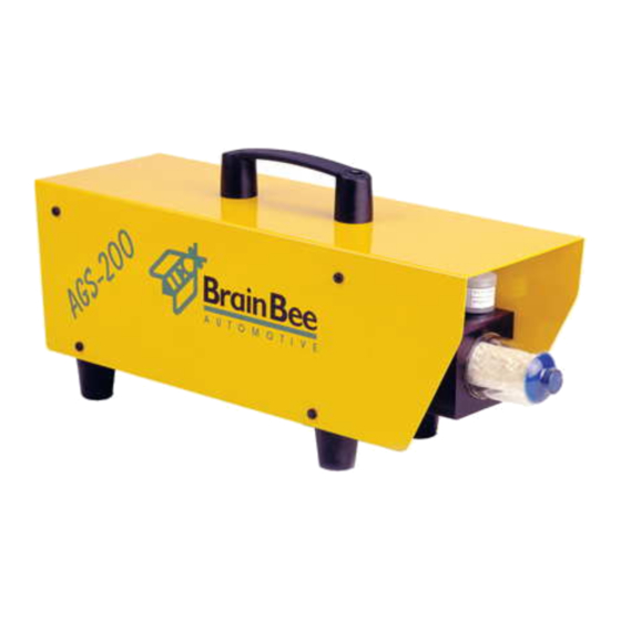
Page 16: Chap. 4 - General Description
ags-200 CHAP. 4 - GENERAL DESCRIPTION 4.1 EXTERNAL ASPECT OF AGS-200 4.1.1 EXTERNAL ASPECT OF AGS-200 OVERALL VIEW FRONT PANEL ENGLISH 15 / 15 CHAP. 4 – GENERAL DESCRIPTION... - Page 17 ags-200 REAR PANEL 1) GAS INLET 2) WATER OUTLET 3) ACTIVATED CARBON FILTER 4) GAS OUTLET 5) HOUSING FOR Nox SENSOR 6) O2 SENSOR 7) COALESCENT FILTER 8) ENGINE TEMPERATURE SENSOR INPUT 9) ENGINE RPM SENSOR INPUT 10) SOCKET FOR RS-232 SERIAL LINK POWER SUPPLY COMMUNICATION...
-
Page 18: Accessories
ags-200 4.1.2 ACCESSORIES AGS-200 is supplied with the following accessories GAS SAMPLING PROBE SAMPLING PROBE TUBE SAMPLING PROBE FILTER ENGLISH 17 / 17 CHAP. 4 – GENERAL DESCRIPTION... - Page 19 ags-200 Blank Page CHAP. 4 – GENERAL DESCRIPTION 18 / 18 ENGLISH...
-
Page 20: Chap. 5 - General Specifications
ags-200 CHAP. 5 - GENERAL SPECIFICATIONS 5.1 GENERAL SPECIFICATIONS * Measuring ranges : • CO......from 0 to 9.99 Res. 0.01 • CO2......from 0 to 19.9 Res. 0.1 • HC hexane....from 0 to 10000 Res. 1 • 02......from 0 to 100 Res. - Page 21 ags-200 Blank Page CHAP. 5–GENERAL SPECIFICATION 20 / 20 ENGLISH...
-
Page 22: Chap. 6 - Preliminary Operations
ags-200 CHAP. 6 - PRELIMINARY OPERATIONS 6.1 INSTALLATION AGS-200 is supplied in a cardboard box. To open the box, cut the adhesive tape with a cutter and take out the instrument, which is protected by two pieces of moulded polystyrene. If you have a TRO-040 or TRO-010 trolley, place AGS-200 in the relative support as shown in the figure. - Page 23 OMNIBUS 500 AGS 200 OPA 100 CHAP. 6 – PRELIMINARY OPERATION 22 / 22 ENGLISH...
- Page 24 PERSONAL COMPUTER AGS 200 OPA 100 ENGLISH 23 / 23CHAP. 6 – PRELIMINARY OPERATION...
-
Page 25: How To Install The Software
ags-200 6.2 HOW TO INSTALL THE SOFTWARE If you have an OMNIBUS-500, OMNIBUS-500/S or OMNIBUS-400 instrument there is no need to install any particular software as these instruments already have programs able to operate with AGS-200 (refer to the instruction manuals of the instruments for the necessary settings). - Page 26 ags-200 After a presentation mask which can be quitted by pressing any key or by clicking with the mouse, the management program displays the main menu. This allows all the monitoring programs to be accessed and all the necessary settings to be made. ENGLISH 25 / 25CHAP.
-
Page 27: Garage Data Entry
ags-200 6.5.1 GARAGE DATA ENTRY Press F7 "SET-UP" in the main menu and then press F1 "GARAGE DATA" This mask allows you to enter the name and address of the garage where the instruments are used, so that the information is printed on all the test reports. Five lines of 24 characters each are available, plus a line where the test technician's name can be written. -
Page 28: Date And Time Setting
ags-200 6.5.2 DATE AND TIME SETTING Press F7 "SET-UPS" in the main menu and then press F8 "DATE AND TIME SET-UP" This mask allows you to enter the date and time so that this information is automatically printed when the instruments are used. Press F1 to memorize all the values. -
Page 29: Serial Port Set-Up
ags-200 6.5.3 SERIAL PORT SET-UP The program must be informed about the serial port of the computer to which AGS-200 will be connected. Press F7 "SET-UPS" in the main menu and then press F1 "GARAGE DATA" Using the arrows “ “... -
Page 30: Revolution Counter Set-Up
ags-200 6.5.4 REVOLUTION COUNTER SET-UP AGS-200 must be informed whether radio revolution counter MGT-300, MG-7000 with accessory MG-7011 or a normal piezo sensor are to be used. Access the main menu, press F1 "EXHAUST GAS ANALYSIS", then F6 "CONTROLS" and lastly F2 "TYPE OF REV COUNTER". - Page 31 ags-200 Blank Page CHAP. 6 – PRELIMINARY OPERATION 30 / 30 ENGLISH...
-
Page 32: Chap. 7 - Use Of The Instrument
ags-200 CHAP. 7 - USE OF THE INSTRUMENT 7.1 USE OF THE PROGRAM IN A PERSONAL COMPUTER OR IN OMNIBUS Access the main menu and press F1 "EXHAUST GAS ANALYSIS" The GAS ANALYSER menu will appear on the display. The software version that resides in AGS-200 is displayed in the indicated box. ENGLISH 31 / 31CHAP.7 –... -
Page 33: Gas Reading In Continuous Mode
ags-200 7.1.1 GAS READING IN CONTINUOUS MODE Access the main menu of the EXHAUST GAS ANALYZER and press F1 "CONTINUOUS TEST" This accesses the CONTINUOUS TEST mask. The gas reading can only be made at the end of the warming up period and the auto- calibration procedures. - Page 34 ags-200 There are no time limits to this type of test since the instrument can be used for as long as it is required. The measurements can also be displayed in graphic form in two different formats: continuous linear graph or histograms. The functions of the keys that appear on the right hand side of the display are listed below: Immediately prints the displayed values...
-
Page 35: Gas Value Reading In Compliance With Standard Cee
ags-200 7.1.2 GAS VALUE READING IN COMPLIANCE WITH STANDARD CEE 92/55 Access the main menu of the EXHAUST GAS ANALYZER and press F2 to access the "OFFICIAL TEST" mask. The parameters required by CEE 92/55 are displayed in this mask. 7.1.2.1 VEHICLE DATA ENTRY It is obligatory to enter the data in this mask as they determine the type of procedure... -
Page 36: Environmental Test Conditions
ags-200 7.1.2.2 ENVIRONMENTAL TEST CONDITIONS To conduct a test in compliance with CEE 92/55, the environmental conditions must be within the following limits: - TEMPERATURE : between 5 and 40 C° - PRESSURE : between 850 and 1025 mbar The environmental data can be entered in this mask. If they are not entered, they can be written on the print-out at the end of the test. -
Page 37: Residue Hc Test
ags-200 7.1.2.3 RESIDUE HC TEST The next step is to check for any residue HC that may have remained in the measuring circuit after the previous test. At the end of this phase, the following mask will appear: CHAP.7 – USE OF THE INSTRUMENT 36/ 36 ENGLISH... -
Page 38: Vehicle Engine Temperature Test
ags-200 7.1.2.4 VEHICLE ENGINE TEMPERATURE TEST At this stage, you must wait until the engine warms up according to the manufacturer's instructions or, in the absence of these, proceed with the test when the temperature exceeds 80 degrees. To measure the temperature, insert the supplied probe in place of the dipstick. Once the minimum temperature has been reached, the test will automatically pass on to the next mask. -
Page 39: Gas Reading
ags-200 7.1.2.5 GAS READING Before beginning the test, make sure that the probe has been correctly inserted into the exhaust pipe of the vehicle and that it has not encountered any impediments or obstructions The test will now proceed in different ways, depending on the type of vehicle: * Only at idling rate if the vehicle does not have a catalytic silencer. -
Page 40: Print-Out Of Results
ags-200 7.1.2.6 PRINT-OUT OF RESULTS The test results can be printed by means of the printer connected to your system or with the 24-column printer if you are using OMNIBUS-500 The name of the operator who conducted the test can be entered in the official print-out. 7.1.2.7 EXHAUST LIMITS VEHICLES WITH CATALYTIC SILENCERS... -
Page 41: How To Check The Calibration Due Date
ags-200 7.1.3 HOW TO CHECK THE CALIBRATION DUE DATE Access the main menu OF THE exhaust gas analyzer, press F6 "SET-UPS" and then "CALIBRATION DUE DATE". Press 'ESC' to return to the previous menu. CHAP.7 – USE OF THE INSTRUMENT 40/ 40 ENGLISH... -
Page 42: Leak Test
ags-200 7.1.4 LEAK TEST Access the main menu of the EXHAUST GAS ANALYZER, press F6 "CONTROLS" and then F5 "LEAK TEST" The following mask will appear with instructions on how to carry out the leak test. Fit the probe tube into the relative housing as shown in the figure. If the result of the leak test is positive, the analysis program will proceed in the normal way, failing this a message will appear to indicate that the test has not been successful. -
Page 43: Residue Hc Test
ags-200 7.1.5 RESIDUE HC TEST The residue HC test activates automatically during the official test or can be activated by accessing the CONTROLS menu (F6) and then pressing F4. The following mask with the message WAIT PLEASE will appear during the test. This gives the analyzer sufficient time to carry out the "autozero"... -
Page 44: O2 Sensor Efficiency
ags-200 If this value exceeds 20 PPM the test will have failed, otherwise the program will proceed in the normal way.. If the test fails, it can be repeated to bleed the probe filters and tubes. If the test repeat is also unsuccessful, the filters must be changed and the tubes and sampling probe adequately cleaned. -
Page 45: Special Tests
ags-200 If the measuring range is in the yellow zone, the sensor is becoming exhausted but can still be used for a short while. If the measuring range is in the red zone, the sensor is exhausted and must be replaced. -
Page 46: Carburation Test
ags-200 7.1.7.1 CARBURATION TEST This test begins with a warning for the operator. The test involves sampling the exhaust fumes at various engine rates. The operator must comply with the instructions that appear on the screen. The test result will appear at the bottom left of the window at the end of the procedure. ENGLISH 45 / 45CHAP.7 –... -
Page 47: Gas Diagnosis
ags-200 7.1.7.2 GAS DIAGNOSIS This test begins with a request for the operator about the type of vehicle tested. The test involves measuring the exhaust fumes at 2000-2500 rpm and idling engine rates. The operator must comply with the instructions that appear on the screen. The test result will appear at the bottom right of the window at the end of the procedure. -
Page 48: Efficiency Of The Catalytic Unit
ags-200 7.1.7.3 EFFICIENCY OF THE CATALYTIC UNIT During the test, the exhaust fumes are measured at 2000-2500 rpm and idling engine rates with the gas sampling probe inserted first prior to the catalytic unit and then after it. The operator must comply with the instructions that appear on the screen. -
Page 49: Head Gasket Tightness
ags-200 7.1.7.4 HEAD GASKET TIGHTNESS The test checks for carbon monoxide (CO) in the cooling circuit. The operator must comply with the instructions that appear on the screen. The test result will appear at the bottom left of the window at the end of the procedure. CHAP.7 –... -
Page 50: Engine Warming-Up Efficiency
ags-200 7.1.7.5 ENGINE WARMING-UP EFFICIENCY This test begins with a warning for the operator The exhaust fumes are sampled at regular intervals after the engine (which must idle) has started. At the end of the test, which lasts 15 minutes, the operator must visually check that emissions of the four gases have dropped between the instant the engine fired to the time when the correct engine operating temperature has been reached. - Page 51 ags-200 BLANK PAGE CHAP.7 – USE OF THE INSTRUMENT 50/ 50 ENGLISH...
-
Page 52: Chap. 8 - Maintenance
This chapter contains all the instructions you require to keep your instrument in a perfectly efficient condition. The BRAINBEE Assistance Department will be happy to supply you with all the information and means required to achieve this result in a rapid and efficient way. - Page 53 ags-200 Unscrew the cup to replace the coalescent filter, indicated by the arrow. Once the coalescent filter has been removed, the gauze filter indicated by the arrow can be replaced (or washed with soap and water). CHAP.8 – MAINTENANCE 52/ 52 ENGLISH...
-
Page 54: How To Replace The Activated Carbon Filter
ags-200 8.2 HOW TO REPLACE THE ACTIVATED CARBON FILTER This filter eliminates the dust and unburnt hydrocarbons in the environment from the air used to autozero the instrument. When the instrument is used in optimum conditions, this filter should be replaced once a year. - Page 55 ags-200 BLANK PAGE CHAP.8 – MAINTENANCE 54/ 54 ENGLISH...
-
Page 56: Chap. 9 - Errors
ags-200 CHAP. 9 - ERRORS This chapter lists all the errors that may appear as the instrument is used. Full comments to all the errors displayed appear on the screen, thus further descriptions are not considered necessary. ERROR Cause Remedy Ref. - Page 57 ags-200 BLANK PAGE CHAP.9 – ERRORS 56/ 56 ENGLISH...
-
Page 58: Chap. 10 - Optionals
OPA-100, AGS-200 and MANAGER- 600. ST-010 Temperature probe MGT-300, AGS-00, OPA- 100 and MANAGER -600 (Length 2m.) For up to date information, contact your dealer or our website www.brainbee.com ENGLISH 57 / 57 CHAP. 10 – OPTIONALS... - Page 59 ags-200 BLANK PAGE CHAP. 10 – OPTIONALS 58/ 58 ENGLISH...
Need help?
Do you have a question about the AGS 200 and is the answer not in the manual?
Questions and answers