
Related Manuals for EarthLinked TXV Kit


Summary of Contents for EarthLinked TXV Kit
- Page 1 ® EarthLinked TXV Kit Installation Manual Classic and Prime Systems TXV–CLP-KIT (07/15) Copyright 2015 Earthlinked Technologies, Inc.
-
Page 2: Model Nomenclature
All EarthLinked components must be installed and serviced by a technician authorized by Earthlinked Technologies. Installation and service must be made in accordance with the instructions set forth in this manual. Failure to provide installation and service by an authorized installer consistent with this manual will void the limited warranty coverage for the system. -
Page 3: Table Of Contents
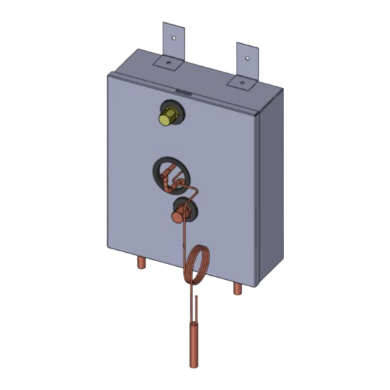
Air Handler and Cased Coil Placement ................. 7 TXV Kit Installation – ETI Air Handlers ................8 TXV Kit Installation – ETI Cased Coils ................ 18 TXV Kit Installation: Non-ETI Brand Air Handler or Cased Coil ......27 TXV–CLP-KIT (07/15) Page 3... - Page 4 List of Figures Figure 1. Component Matching Table ....................6 Figure 2. General Layout of System Components ................7 Figure 3. TXV Control ........................8 Figure 4a. TXV Control Installed on Vertical (upflow/downflow) Air Handler ........9 Figure 4b. TXV Control installed next to Vertical (upflow/downflow) Air Handler ......10 Figure 4c.
-
Page 5: Safety
Equipment Manuals The following is a listing of the equipment installation manuals that are provided with each ® component specified for this EarthLinked system. IMPORTANT! Read and follow all installation instructions in these manuals, ®... -
Page 6: Component Matching
Component Matching Upon receipt of the TXV Kit carefully check the model number against the bill of lading. The TXV Kit must be matched with the appropriately sized compressor unit. See Figure 1 below for correctly matched components. COMPONENT MATCHING TABLE... -
Page 7: Air Handler And Cased Coil Placement
Air Handler and Cased Coil Placement Guidelines for the air handler and cased coil placement relative to the compressor unit and other ® EarthLinked system components are shown in Figure 2. Figure 2. General Layout of System Components TXV–CLP-KIT (07/15) -
Page 8: Txv Kit Installation - Eti Air Handlers
Kit that must be field installed to enable operation of the system in the cool mode. The following procedure is for the installation of the TXV Kit which must be done prior to making the line set connections to the air handler. -
Page 9: Figure 4A. Txv Control Installed On Vertical (Upflow/Downflow) Air Handler
The TXV control box is field positioned external to the vertical (upflow or downflow) air handler and fastened to (1) the air handler as shown in Figure 4a,or (2) on a solid mounting surface immediately adjacent to the air handler as shown in Figure 4b. Locate the TXV control box to allow a service access of at least 12 inches in front of the box to adjust the TXV control. -
Page 10: Figure 4B. Txv Control Installed Next To Vertical (Upflow/Downflow) Air Handler
Figure 4b. TXV Control installed next to Vertical (upflow/downflow) Air Handler For horizontal air handler applications (left or right air flow), the TXV control box is field positioned external to the air handler and can be fastened to (1) a cabinet side surface or (2) on a solid mounting surface immediately adjacent to the air handler as shown typically in Figures 4c and 4d. -
Page 11: Figure 4C. Txv Control Installed Next To Horizontal Left Flow Air Handler
Figure 4c. TXV Control Installed next to Horizontal Left Flow Air Handler Figure 4d. TXV Control Installed next to Horizontal Right Flow Air Handler TXV–CLP-KIT (07/15) Page 11... -
Page 12: Figure 4E. Txv Control Box Dimensions
For mounting purposes, the physical dimensions for the TXV Control Box are shown in figure 4e. The preferred mounting position for the TXV Control Box is vertical with the liquid line tube connections on the bottom. However, as shown in Figure 4f, the Control Box can be mounted from vertical to any angle up to 90 degrees (horizontal). -
Page 13: Figure 4F. Txv Control Box Mounting Positions
Figure 4f. TXV Control Box mounting Positions The following steps and positioning requirements apply to installing the TXV Control to the air handler for vertical and horizontal applications. The vertical installation provides an illustrated example. TXV–CLP-KIT (07/15) Page 13... -
Page 14: Figure 5. Positioning The Pressure Equalizer Tee
Step 1: Relieve the nitrogen holding charge on the air handler. Locate the TXV Control box within the 3-1/2 feet of the suction line stub out on the air handler. If the TXV control box is to be fastened to the air handler, be sure not to drill into the air handler internal components. Fasten the TXV control box above the suction line stub out. -
Page 15: Figure 6. Thermal Bulb Positioning
Step 3: The Thermal Bulb must be positioned and clamped to the suction tube 6 inches downstream from the 90° elbow as shown in the example illustrated in Figure 6. The Thermal Bulb and suction tube must be horizontal regardless of the air handler application (vertical or horizontal). -
Page 16: Figure 7. Clamping The Thermal Bulb
Figure 7. Clamping the Thermal Bulb Figure 8. Insulating the Thermal Bulb TXV–CLP-KIT (07/15) Page 16... -
Page 17: Figure 9. Txv Liquid Line Connections
Step 5: Measure and cut copper tubing to connect the liquid line from the TXV control box to the liquid line stub out on the air handler as shown in Figures 3 and 9. Run the other liquid line from the connection on the TXV control box to the compressor unit, also shown in Figures 3 and 9. -
Page 18: Txv Kit Installation - Eti Cased Coils
Kit that must be field installed to enable operation of the system in the cool mode. The following procedure is for the installation of the TXV Kit which must be done prior to making the line set connections to the cased coil. -
Page 19: Figure 11A. Txv Control Installed Near Cased Coil (Vertical Application)
The TXV control box is field positioned external to the vertical (upflow or downflow) cased coil and fastened to a solid mounting surface immediately adjacent to the cased coil as shown typically in Figure 11a. Locate the TXV control box to allow a service access of at least 12 inches in front of the box to adjust the TXV control. -
Page 20: Figure 11B. Txv Control Installed Near Cased Coil (Horizontal Application)
For horizontal cased coil applications (left or right air flow), the TXV control box is field positioned external to the cased coil and can be fastened to a solid mounting surface immediately adjacent to the cased coil as shown typically in Figure 11b. Important! The TXV control box must be located no more than 3-1/2 feet from the suction tube stub out on the cased coil. -
Page 21: Figure 11C. Txv Control Box Dimensions
For mounting purposes, the physical dimensions for the TXV Control Box are shown in figure 11c. The preferred mounting position for the TXV Control Box is vertical with the liquid line tube connections on the bottom. However, as shown in Figure 11d, the Control Box can be mounted from vertical to any angle up to 90 degrees (horizontal). -
Page 22: Figure 11D. Txv Control Box Mounting Positions
Figure 11d. TXV Control Box Mounting Positions The following steps and positioning requirements apply to installing the TXV Control to the cased coil for vertical and horizontal applications. The vertical installation provides an illustrated example. Step 1: Relieve the nitrogen holding charge on the air handler using the valve on the liquid line stub out. -
Page 23: Figure 12. Positioning The Pressure Equalizer Tee
Step 2: Position the Pressure Equalizer Tee on the suction tube at least 10 inches downstream from the 90° ell as shown in Figure 12. Remove the core from Schrader valve on the Tee. Figure 12. Positioning the Pressure Equalizer Tee TXV–CLP-KIT (07/15) Page 23... -
Page 24: Figure 13. Thermal Bulb Positioning
Step 3: The Thermal Bulb must be positioned and clamped to the suction tube as shown in the example illustrated in Figure 13. The Thermal Bulb and suction tube must be horizontal regardless of the cased coil application (vertical or horizontal). The Thermal Bulb must be positioned at the 3:00, 4:00, 8:00 or 9:00 positions on the suction tube, as illustrated in Figure 13. -
Page 25: Figure 14. Clamping The Thermal Bulb
Figure 14. Clamping the Thermal Bulb Figure 15. Insulating the Thermal Bulb TXV–CLP-KIT (07/15) Page 25... -
Page 26: Figure 16. Txv Liquid Line Connections
Step 5: Measure and cut copper tubing to connect the liquid line from the TXV control box to the liquid line stub out on the cased coil as shown in Figures 10 and 16. Run the other liquid line from the connection on the TXV control box to the compressor unit, also shown in Figure 16. -
Page 27: Txv Kit Installation: Non-Eti Brand Air Handler Or Cased Coil
Important! A TXV Kit installed on a NON-ETI brand air handler or cased coil must be pre-approved by ETI Technical Support and installed in accordance with the foregoing instructions for AVS and CCS Series products, and the instructions that follow. -
Page 28: Figure 17. Typical Air Handler/Cased Coil After Conversion
Distributor and Feeder Tubes Orientation After modifying the distributor as described above, the distributor and feeder tubes are to be carefully oriented so that the distributor is vertically upward or downward for the final orientation (vertical or horizontal) of the air handler or cased coil. This is illustrated in Figure 17.
Need help?
Do you have a question about the TXV Kit and is the answer not in the manual?
Questions and answers