
Related Manuals for SAF-HOLLAND SBS 2220 K0


Summary of Contents for SAF-HOLLAND SBS 2220 K0
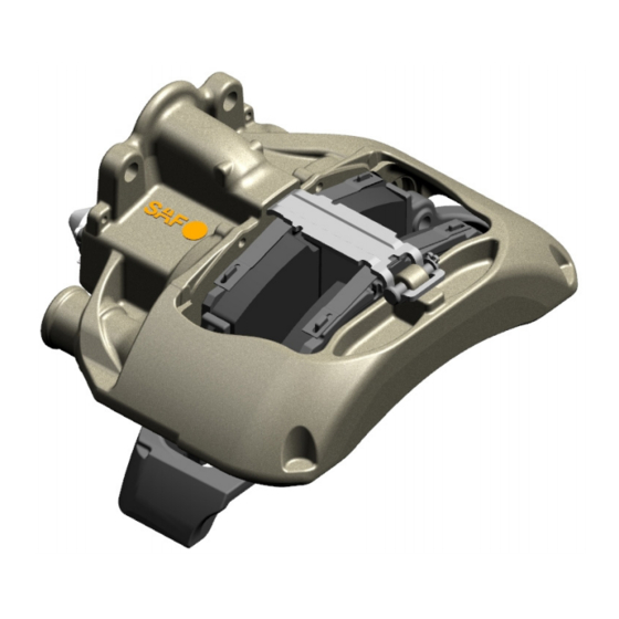
- Page 1 Repair Instructions Compressed Air Disc Brake SAF SBS 2220 K0 XL-SA40001RM-en-DE Rev A • 02.2016 Translation of the original repair instructions...
- Page 2 Use only genuine SAF-HOLLAND GmbH spare parts in repairs. This manual is subject to the copyright of SAF-HOLLAND GmbH. All rights reserved. No part of this manual may be reproduced, copied or translated in any form or by any means without the prior written permission of SAF-HOLLAND GmbH.
-
Page 3: Table Of Contents
Installing the bellows (9) 10. Replacing the brake chamber 10.1 Removing the diaphragm chamber 10.2 Fitting the diaphragm chamber 10.3 Removing the combined chamber 10.4 Fitting the combined chamber XL-SA40001RM-en-DE Rev A • 02.2016 • Errors and changes excluded © SAF-HOLLAND... - Page 4 ATTENTION: SAF-HOLLAND SHALL NOT BE LIABLE FOR ANY INJURY OR DAMAGE RESULTING FROM THE IMPROPER USE OF SERVICE KITS OR SERVICE TOOLS: IMPROPER USE OF SERVICE TOOLS AND IMPROPER ATTACHMENT OR APPLICATION OF SERVICE KITS CAN GIVE RISE TO DAMAGE OR HAZARDOUS HANDLING.
- Page 5 17. Use of an impact wrench in conjunction with SAF-HOLLAND service tools for pneumatic disc brakes is not permitted. SAF-HOLLAND service tools have not been designed for use of an impact wrench. Use of an impact wrench can damage the service tools and vehicle resulting in a risk of injury.
-
Page 6: Component Overview
22 Inner seal 68 Cover 9 Bellows 26 Spring cotter pin 161 Slide bearing bushing 10 Cover 37 Cap Variants 11 Pad retainer Diaphragm chamber or combined chamber XL-SA40001RM-en-DE Rev A • 02.2016 • Errors and changes excluded © SAF-HOLLAND... -
Page 7: Brake Identification And Service Kits For The Disc Brake
101 Wear contact clip sensor with cable brake discs be replaced after a period of six years, 104 Cable guide plate even if they do not appear to be worn. 105 Cable guide XL-SA40001RM-en-DE Rev A • 02.2016 • Errors and changes excluded © SAF-HOLLAND... -
Page 8: General Information
General information 2. General information Use of an impact wrench in conjunction with SAF-HOLLAND tools for pneumatic disc brakes is not permitted. Never rotate the adjuster (23) without an adapter (61). The adapter (61) will be irreparably damaged if its prescribed demolition torque is exceeded. -
Page 9: Structure And Function
40 Socket cap screw 44 Bolt 45 Washer 46 Brake disc 58 Ring 61 Adapter 68 Cover 161 Slide bearing bushing Observe variants Diaphragm chamber or combined chamber XL-SA40001RM-en-DE Rev A • 02.2016 • Errors and changes excluded © SAF-HOLLAND... -
Page 10: Functional Description
Releasing the brake exceeded. If braking pressure is reduced, the compression spring (27) presses the bridge (17) with threaded pipes (16) and lever (19) back into the initial position. XL-SA40001RM-en-DE Rev A • 02.2016 • Errors and changes excluded © SAF-HOLLAND... -
Page 11: Inspection Points
(13), cap (37), sealing elements (9, 58) and calliper bearing in the slide bearing (6) area must be checked for clearance and damage (see Chap. 5.3.4). XL-SA40001RM-en-DE Rev A • 02.2016 • Errors and changes excluded © SAF-HOLLAND... -
Page 12: Safety Instructions For Service And Repair Work
Observe the safety and environmental guidelines Use the recommended tools (see Chap. 2.1). on pages 5 and 6. Tighten screws, nuts and bolts to the prescribed tightening torques (see Chap. 2.4). XL-SA40001RM-en-DE Rev A • 02.2016 • Errors and changes excluded © SAF-HOLLAND... -
Page 13: Function And Visual Inspection
5.1.3 - Dimensions of brake pad and brake discs In the event that dimension E ≤ 39 mm, the brake disc must also be replaced when replacing the pad. XL-SA40001RM-en-DE Rev A • 02.2016 • Errors and changes excluded © SAF-HOLLAND... - Page 14 Brake disc polishing is impermissible. Danger ! There is a risk of accident if these regulations are not observed! Worn brake pads and/or over-worn brake discs will reduce or stop braking efficiency. XL-SA40001RM-en-DE Rev A • 02.2016 • Errors and changes excluded © SAF-HOLLAND...
- Page 15 (see Fig.). Note ! Observe the information from the respective vehicle manufacturer. 5.1.6 - Electrical wear indicator XL-SA40001RM-en-DE Rev A • 02.2016 • Errors and changes excluded © SAF-HOLLAND...
-
Page 16: Inspecting The Adjustment Function
5.2.6.6 Actuate the brake 20x with medium pres- sure (approx. 2-3 bar). 5.2.6.4 - Removing the cap and using the adapter on the adjuster XL-SA40001RM-en-DE Rev A • 02.2016 • Errors and changes excluded © SAF-HOLLAND... - Page 17 If the ring spanner or socket fails to rotate, does so only on the first actuation or every actuation backwards and forwards, the adjuster is faulty and the brake calliper must be replaced. XL-SA40001RM-en-DE Rev A • 02.2016 • Errors and changes excluded © SAF-HOLLAND...
- Page 18 If the clearance at both pressure fittings is still smaller than 0.6 mm, the brake calliper must be replaced. 5.2.9 Fit the wheels (observe the information from the respective vehicle manufacturer). XL-SA40001RM-en-DE Rev A • 02.2016 • Errors and changes excluded © SAF-HOLLAND...
-
Page 19: Checking The Movement Of The Brake Calliper
>25 mm or fails to move at all, the calliper guide must be repaired (see Chap. 9). 5.3.4 - Movement path of the brake calliper XL-SA40001RM-en-DE Rev A • 02.2016 • Errors and changes excluded © SAF-HOLLAND... -
Page 20: Checking The Clearance In The Guide Bearing Area
Otherwise, replace the brake pads axially and set the clearance (see Chap. 6.2). 5.4.8 Fit the wheel. The information from the re- spective vehicle manufacturer must be observed. XL-SA40001RM-en-DE Rev A • 02.2016 • Errors and changes excluded © SAF-HOLLAND... -
Page 21: Inspecting The Sealing Elements
If necessary, replace the pressure fittings (13) with bellows (see Chap. 7). 5.5.4 - Inspecting the bellows XL-SA40001RM-en-DE Rev A • 02.2016 • Errors and changes excluded © SAF-HOLLAND... -
Page 22: Replacing The Brake Pads
(see Fig.). 6.1.5 Pull out the brake pads (12 ) and (12 (see Fig.). 6.1.5 - Pulling out the brake pads XL-SA40001RM-en-DE Rev A • 02.2016 • Errors and changes excluded © SAF-HOLLAND... -
Page 23: Installing The Brake Pads
6.2.4b - Installing the outer brake pad (ST7) calliper groove (1), then press these down in order to position the bolt (44) (use only new parts) (see Fig.). XL-SA40001RM-en-DE Rev A • 02.2016 • Errors and changes excluded © SAF-HOLLAND... - Page 24 Note that the brake pads and/or brake disc may have reduced braking efficiency during their run-in phase. 6.2.8 - Replacing the cap XL-SA40001RM-en-DE Rev A • 02.2016 • Errors and changes excluded © SAF-HOLLAND...
-
Page 25: Mounting The Wear Contacts
(45) and spring cotter pin (26) (see Fig. and Chap. 6.2). Ensure the correct position of the wear indicator cable (101) (see arrows). 6.3.3 - Mounting the pad retainer XL-SA40001RM-en-DE Rev A • 02.2016 • Errors and changes excluded © SAF-HOLLAND... - Page 26 When radial pressure is applied to the cover plate (104), it will lock into place in the pad retainer (11) (see Fig.). 6.3.6 - Mounting the cover plate XL-SA40001RM-en-DE Rev A • 02.2016 • Errors and changes excluded © SAF-HOLLAND...
-
Page 27: Replacing The Pressure Fittings
35 mm and maximum 40 mm, then lever out the bellows with a screwdriv- er (B). 7.1.1 - Unscrewing the pressure fittings, levering out the bellows XL-SA40001RM-en-DE Rev A • 02.2016 • Errors and changes excluded © SAF-HOLLAND... - Page 28 Note: When replacing the pressure fittings with bellows (13), the inner seal (22) must also be replaced (see Fig. 7.1.2b). 7.1.3 - 7.1.4 - Removing the slide bearing bushing, checking the seal XL-SA40001RM-en-DE Rev A • 02.2016 • Errors and changes excluded © SAF-HOLLAND...
-
Page 29: Removing And Installing The Inner Seal
(see Fig.). 7.2.6 Apply the new inner seal (22) to the thread- 7.2.3 - 7.2.5 - Screw out the threaded pipes and ed pipe (16). smear with white grease XL-SA40001RM-en-DE Rev A • 02.2016 • Errors and changes excluded © SAF-HOLLAND... - Page 30 7.2.14 Unscrew the threaded pipe (16) approx. 4-5 threads via the adjuster (23) with the adapt- er (61). The inner seal (22) must not be allowed to turn. XL-SA40001RM-en-DE Rev A • 02.2016 • Errors and changes excluded © SAF-HOLLAND...
-
Page 31: Mounting The Pressure Fittings With Bellows
7.3.7 Press in the bellows of the pressure fitting (13) with the tool component (E1) (see Fig.). 7.3.7 - Pressing in the bellows with the tool component (E1) XL-SA40001RM-en-DE Rev A • 02.2016 • Errors and changes excluded © SAF-HOLLAND... - Page 32 (T28) (see Fig.). 7.3.10 Remove the tool combination (E2). 7.3.9 - Pressing in the pressure fitting with the tool combination (E2) XL-SA40001RM-en-DE Rev A • 02.2016 • Errors and changes excluded © SAF-HOLLAND...
- Page 33 (see Fig.). 7.3.13 - Pressing in the bellows of the pressure fitting with the long tool combination (E3) 7.3.14 - Pressure fittings must rotate slightly in both directions XL-SA40001RM-en-DE Rev A • 02.2016 • Errors and changes excluded © SAF-HOLLAND...
-
Page 34: Removing And Installing The Brake Calliper
Check the bearing area of the calliper bore for corrosion and repair with a suitable guide and seal kit if necessary. In the event of severe damage or corrosion, the brake calliper must be replaced. XL-SA40001RM-en-DE Rev A • 02.2016 • Errors and changes excluded © SAF-HOLLAND... - Page 35 (11) as this can damage the pad retainer. • The brake calliper must not be opened or disassembled - "Risk of accident". 8.1.7 Remove the brake calliper (1) from the carrier (2). XL-SA40001RM-en-DE Rev A • 02.2016 • Errors and changes excluded © SAF-HOLLAND...
-
Page 36: Mounting The Brake Calliper To The Carrier (Carrier Not Removed)
8.2.3 Check the correct seating of the inner bel- lows (9) and the rings (58) on the guide bushings (4, 5) (see Fig.). XL-SA40001RM-en-DE Rev A • 02.2016 • Errors and changes excluded © SAF-HOLLAND... - Page 37 8.2.11 - Positioning the press-in tool (H) with cover flat surface of the calliper bore (see Fig.). on the flat surface of the calliper bore Note: Do not tilt the tool! XL-SA40001RM-en-DE Rev A • 02.2016 • Errors and changes excluded © SAF-HOLLAND...
- Page 38 The inner bellows (9) must compressed as otherwise the movement of the brake calliper will be restricted. 8.2.14 - Positioning the press-in tool (M) with cover on the flat surface of the calliper bore XL-SA40001RM-en-DE Rev A • 02.2016 • Errors and changes excluded © SAF-HOLLAND...
- Page 39 Note that the brake pads and/or brake disc may have reduced braking efficiency during their run-in phase. XL-SA40001RM-en-DE Rev A • 02.2016 • Errors and changes excluded © SAF-HOLLAND...
-
Page 40: Repairing The Brake Calliper Bearing
9.2.1 Clean the spot face (arrow A) and the bush- ing (7) (see Fig.). 9.2 - Tool combination (D) 9.2.1 - Cleaning the spot face and the bushing XL-SA40001RM-en-DE Rev A • 02.2016 • Errors and changes excluded © SAF-HOLLAND... - Page 41 (T14) as far as it (see Fig.). will go 9.2.6 Insert the bushing (7) via the brass nut (T14) as far as it will go (see Fig.). XL-SA40001RM-en-DE Rev A • 02.2016 • Errors and changes excluded © SAF-HOLLAND...
-
Page 42: Replacing The Slide Bearing (6) On The Short Bearing Side
AF24 and use a suitable tool (e.g. ratchet wrench AF24) to turn the screws on T20 and pull out the slide bearing (6) (see Fig.). 9.3.4 - 9.3.6 - Pulling out the slide bearing XL-SA40001RM-en-DE Rev A • 02.2016 • Errors and changes excluded © SAF-HOLLAND... -
Page 43: Installing The Bellows
(see Chap. 2.1). 9.4.1 To install the bellows (9), use the tool com- bination (C) with the tool component (T08). 9.4.1 - Tool combination (C) XL-SA40001RM-en-DE Rev A • 02.2016 • Errors and changes excluded © SAF-HOLLAND... - Page 44 9.4.4 - Inserting with max. torque of 8 Nm 9.4.7 Install the guide bushings (4, 5) (see Fig.). 9.4.5 - Ensuring the correct seating of the bellows 9.4.7 - Inserting the guide bushing XL-SA40001RM-en-DE Rev A • 02.2016 • Errors and changes excluded © SAF-HOLLAND...
- Page 45 (9) in the groove of the guide bushing (4, 5) (see Fig.). 9.4.11 Mount the brake calliper to the carrier (see Chap. 8.2). 9.4.10 - Securing the bellows with ring XL-SA40001RM-en-DE Rev A • 02.2016 • Errors and changes excluded © SAF-HOLLAND...
-
Page 46: Replacing The Brake Chamber
Danger ! Do not use grease containing molybdenum disulphide! Use only approved diaphragm chambers in accordance with the information 11.2.3 - Checking the seal from the vehicle manufacturer. XL-SA40001RM-en-DE Rev A • 02.2016 • Errors and changes excluded © SAF-HOLLAND... -
Page 47: Removing The Combined Chamber
(18) and remove the com- bined chamber (18) (see Fig.). Danger ! 11.3.5 - Removing the SAF-HOLLAND combined chamber Unscrew the hex nuts from the combined chamber (18) and do not re-use. XL-SA40001RM-en-DE Rev A • 02.2016 • Errors and changes excluded © SAF-HOLLAND... -
Page 48: Fitting The Combined Chamber
Perform a function and effectiveness check of on the cylinder. the BBA +FBA ! 10.4.9 Check that the air connections are leak tight. XL-SA40001RM-en-DE Rev A • 02.2016 • Errors and changes excluded © SAF-HOLLAND... - Page 49 Emergency hotline +49 6095 301-247 Customer Service +49 6095 301-602 +49 6095 301-259 service@safholland.de www.safholland.com SAF-HOLLAND GmbH Hauptstraße 26 D-63856 Bessenbach...
Need help?
Do you have a question about the SBS 2220 K0 and is the answer not in the manual?
Questions and answers