
Related Manuals for Haefely 2830


Summary of Contents for Haefely 2830
- Page 1 2830/2831 Precision Liquid and Solid Dielectric Analyzer User Manual 4843477-M | Version 3.0...
- Page 2 Revision History Version Date Author Remarks 2013-12 release 2021-07 release...
- Page 3 Although all efforts are made to ensure that there are no errors in the manuals, HAEFELY accepts no responsibility for damage or loss that may result from errors within this manual. We retain the right to modify the functionality, specification or operation of the equipment without prior notice.
-
Page 4: Table Of Contents
Contents Introduction General ........................ 1 Scope of Supply ....................1 Accessories and Options ..................2 Hardware ......................2 Software ....................... 2 Glossary of Terms and Abbreviations Safety General ........................ 4 3.1.1 Five basic safety regulations ..............5 3.1.2 Ground Connections ................6 3.1.3 Test Area .................... - Page 5 Front Panel 2830 ....................25 Rear Panel 2830 ....................25 Front Panel 2831 ....................27 Rear Panel 2831 ....................28 Assembling and Installation Guide Mounting of 2830 and 2831 ................29 Inter-wiring of 2830 and 2831 ................29 Software General ......................30 9.1.1 Start-up ....................
- Page 6 Packing and Transport ..................102 Recycling 14.1 Recycling ......................103 Troubleshooting 15.1 Windows Recovery ..................104 15.2 Software Updates 2830 ................... 105 15.3 FAQ ........................105 15.4 Error Assistance ....................106 15.4.1 ComError ................... 106 Service, Maintenance and Contact Information 16.1...
- Page 7 Conformity Notes Introduction...
- Page 8 VIII Introduction...
-
Page 9: Introduction
While the manual mode provides quick measurements, the automatic test mode supports complete automated test sequences according the standards. 1.2 Scope of Supply The following items are supplied: Description Precision Oil and Solid Analyzer 2830/2831 Inter-Wiring cable set Mains cable 10A and 16A (country specific) Operating instruction Test certificate Test cables corresponding to order On receipt of the unit check that all items have been delivered. -
Page 10: Accessories And Options
Liquid test cell- 2903 Solid test cell- 2914 Note: If you use existing oil test cells 2903 or solid test cells 2914 with the 2830/2831 you need a new measuring cable set. On receipt of the unit check that all items have been delivered. In the event... -
Page 11: Glossary Of Terms And Abbreviations
2 Glossary of Terms and Abbreviations In the manual, the following conventions are used: Indicates a hint or a matter of note - if it refers to a sequence of operations, failure to follow the instructions may result in measurement errors. Indicates hazards. -
Page 12: Safety
HAEFELY and its sales partners refuse to accept any responsibility for consequential or direct damage to persons and/ or goods due to none observance of instructions contained herein or due to incorrect use of the equipment. -
Page 13: Five Basic Safety Regulations
3.1.1 Five basic safety regulations At any entering or working with high voltage systems always consider the five basic safety regulations: 1) Disconnect mains! 2) Prevent reconnection! 3) Test for absence of harmful voltages! 4) Ground and short circuit! 5) Cover or close off nearby live parts! After high voltage tests have been performed the first thing during entering high voltage parts are should be grounded. -
Page 14: Ground Connections
If the equipment has been opened, the calibration can be rendered invalid. HAEFELY and its sales partners accept no liability for loss, damage, injury or death caused by the incorrect or unsafe operation of this instrument. -
Page 15: Health Notes
3.1.6 Health Notes This system produces hazardous voltages that can cause shocks, burns or death. During operation high electric and magnetic fields can occur. The fields can affect to your health. Different measures can help here to reduce the risk (example: shielding against the fields, increase of the distance to the high voltage system, duration of the test, lower voltage/ current levels). -
Page 16: Technical Data
4 Technical Data 4.1 Specifications Measurement 2830 Range Accuracy Max. Resolution 0.5 % rdg 1 x 10 Dissipation Factor (tan 0 .. 100 1 x 10 ) 10 pF 0.2 % rdg 0.01 pF 0.001 pF Capacitance Relative Permittivity ... - Page 17 Supply 2831 90 .. 264 VAC, max.1.7 kVA, 50 / 60 Hz Weight 21 kg (2830), 19 kg (2831) 2 pcs 48 x 27 x 44 cm (19” x 10.6” x 17.3”) W x H x D 1 Accuracy values @ 50/60Hz 2 Range limit is given by test current and voltage 3 @ 2.5 kV (Rmax = 2 GΩ...
-
Page 18: Theory
5 Theory 5.1 Dissipation Factor tanδ To specify the insulation loss factor, the test object must be considered in the test arrangement as a capacitor. Consider the liquid test cell and solid test cell. Are constructed from metal and insulation, and therefore possess associated capacitive properties. Every test cell consists of two electrodes: a high voltage and a guarded measuring electrode. -
Page 19: Parallel And Series Equivalent Circuits
Loss factor (Dissipation Factor) Power Factor tan 2 δ Parallel equivalent diagram of a loss capacitance with vector diagram Reactive Powre Apparent Power Real Power applied test voltage Test current through capacitance current through resistance (insulating material) ideal capacitance ideal resistance Because P = Q •... -
Page 20: The Difference Between Power Factor And Dissipation Factor
Series Equivalent Circuit C + Series equivalent circuit Rs Rp * measured values 5.3 The difference between Power Factor and Dissipation Factor While “Dissipation Factor”, tan is used in Europe to describe dielectric losses, the calculation used in the United States is “Power Factor”, cos . - Page 21 The permittivity of free space (vacuum permittivity) also called electric constant is the ratio D/E in free space. It also appears in the Coulomb force constant 1/4πε D= electric displacement field E= electric field = vacuum permittivity = speed of light ...
- Page 22 The relative permittivity can be calculated according the below formula and this according the standards. to solve equations to the below formula results. For For of liquid (oil) of air ...
-
Page 23: Dc Resistivity
ε Material Dissipation factor @ 20°C Vacuum Acetal resin (Delrin™) 0.5% 0.0% 1.00059 Askarels 0.4% Kraft paper, dry 0.6% 2.2 … 2.4 Transformer oil 0.02% Polyamide (Nomex™) 1.0% Polyester film (Mylar™) 0.3% Polyethylene 0.05% Polyamide film (Kapton™) 0.3% Polypropylene 0.05% 6 …... - Page 24 The resistivity of a given specimen my be influenced by the applied stress. For results to be comparable, measurement shall be made with approximately the same electrical stress and polarity. c. Time of electrification Upon the application of DC voltage, the current flow through the specimen decrease due to the sweep of charge carriers to the electrodes.
-
Page 25: Test Instruments
The cell constant can also by calculated according the following formula: − with 5.6 Test Instruments There are three basic kinds of capacitance, tan ... -
Page 26: Evaluation Of Test Results
5.7 Evaluation of Test Results Significance of Capacitance and Dissipation Factor and DC Resistivity A large percentage of electrical apparatus failures are due to a deteriorated condition of the insulation. Many of these failures can be anticipated by regular application of simple tests and with timely maintenance indicated by the tests. -
Page 27: Other Test Methods
Influence of Temperature Most insulation measurements have to be interpreted based on the temperature of the specimen. The dielectric losses of most insulation increase with temperature. In many cases, insulations have failed due to the cumulative effect of temperature, e.g. a rise in temperature causes a rise in dielectric loss which causes a further rise in temperature, etc. -
Page 28: Device Functions
The digitised data streams are fed into the built-in PC of the 2830 and over the known standard capacitor built in the 2831. All other desired measuring values can now be determined online. -
Page 29: Dc Resistivity
The applied voltage and the measured current are converted to digital values for further calculations in the 2830. To calculate the resistivity, four parameters has to be known: The Ix through the solid or liquid sample, the applied voltage Utest, the surface area of the measuring electrode A and the thickness of the test sample l. -
Page 30: Vcommon Point And Guarding
6.1.3 Vcommon point and Guarding This measuring system is able to measure capacitances with highest accuracy to determine trending analysis of insulating materials. In the range of normal insulation capacitances the always existent stray capacitances - measured together wit the DUT – can influence the measuring values significant. - Page 31 Standard connection to measure capacitance and tan of liquid or solid insulating material between high voltage “u” to low voltage “a”. Connection earth to V(Common) has always to be closed, else the high voltage can occurred on the V(common). Device Functions...
-
Page 32: Device Operations
7 Device Operations 7.1 Touch Screen To calibrate the touch screen positioning follow the following steps: • Close or minimize the application software by pressing the minimize button or the close button. ▪ Start “All Programs” / “eGalaxTouch” / “Configure Utility” ▪... -
Page 33: Front Panel 2830
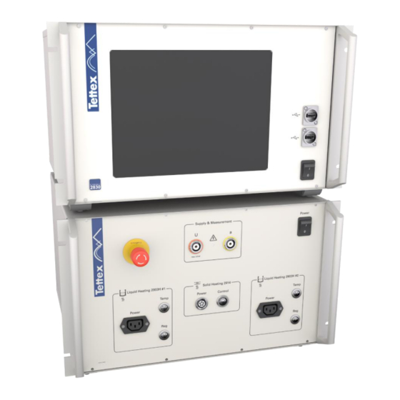
7.2 Front Panel 2830 Touch screen interface USB Interface 1 USB Interface 2 Mains Power Switch 7.3 Rear Panel 2830 Device Operations... - Page 34 Measurement Input Cx Measurement Input Cn (Reference Point of the bridge) (Common) The black jumper must always be connected to the V (Common) If the black jumper is not connected and High Voltage is switched on HIGH VOLTAGE can occurred on the V(Common) point. Earth connection terminal to connect to the 2831 V .
-
Page 35: Front Panel 2831
7.4 Front Panel 2831 Emergency Switch ( Stops AC & DC power supplies and all heaters) HV plug socket for liquid and solid test cell Measuring plug socket for liquid and solid test cell Main power switch Temperature control for liquid heating #2 Temperature regulating for liquid heating #2 Power for liquid heating #2 Temperature control and regulating for solid heating... -
Page 36: Rear Panel 2831
7.5 Rear Panel 2831 Measurement Output Cx Measurement Output Cn (Low Voltage Point of the internal AC power supply) (Common) Interlock 1 Interlock 2 Safety Ground Connection For safety reasons this earth cable should be the FIRST lead to be connected to the set and the LAST to be disconnected. -
Page 37: Assembling And Installation Guide
Check that the main switches are switched 8.2 Inter-wiring of 2830 and 2831 For the inter wiring of the 2830 and 2831 use only the cable which are delivered with the instrument. Connect the 2830 CX to the 2831 CX Connect the 2830 CN to the 2831 CN Connect the 2830 “V”(Common) to the 2831... -
Page 38: Software
9.1.1 Start-up After the system is switched on and the Windows 7 Embedded is started up the 2830 software will automatically start up with a delay of 10 seconds. To start the 2830 software manually - this case could be after closing the software and not shutdown the devices - double click on the following link on the desktop: The following image shows the start up screen of the 2830 software. - Page 39 Once the program has been started the last opened tab sheet appears: e.g. C Tan with selected heater 2903 #1. Software...
-
Page 40: Basic Window Structure
9.1.2 Basic Window structure The software consists of one window with multiple tab sheets on the right side. The buttons on the bottom are dynamic assigned depending on the selected tab sheet. The heater & cell section on the top is also dynamic. It could display either one to two liquid heater, to which one liquid test cell can be assigned, or one solid test cell depending on the heater selection (see 9.3.3 Heating cell(s)). -
Page 41: Heater & Cell Status
Heating cells) you can see one or two liquid heater in the heater & cell section. If no heater is selected then the this section is empty. When the 2830 software is started, then no test cell and file is assigned to the heaters. Software... - Page 42 Assigning a Liquid Test Cell Before a measurement can be made a liquid test cell has to be assigned to a heater, else the HV can not be switched on. With the test cell assigning the according file will also be loaded (on the picture on the right side are two cells with the according filename in the lower left corner).
- Page 43 It includes the heater and the electrodes with guard-ring. Therefore no cell has to be assigned to a heater. When the 2830 software is started, then a temporary file (visible in the right bottom corner of the cell symbol: 2830) will be generated.
- Page 44 measurement results will be deleted. It is recommended to make a new file or open an existing one before the measurements start. (see chapter 9.2 File Manager) Beside the thermometer the current liquid temperature (orange number) and the set target temperature (see chapter 9.3.3 Heating cell(s)) is displayed.
-
Page 45: Basic Buttons
9.1.4 Basic Buttons In the basic buttons area are following buttons available depending on the selected tab sheet: About By clicking on this button the about pop up with software & firmware versions and other info will appear (see chapter 9.3.6 About Screen). - Page 46 Start Test By clicking on this button the DC HV will be applied for the set measuring time and the resistivity measurement starts (see chapter 9.5 DC Resistivity). Available on tab sheet: DC Resistivity Stop Test By clicking on this button the DC HV will be shut down and the measurement aborts (see chapter 9.5 DC Resistivity).
-
Page 47: Title Bar
9.1.5 Title Bar The title bar (header line) has following structure: Device Path and name of Alarm Screen Close / Help Minimize Name the actual active file Messages Shot Shut Down The color of the title bar will change to red while the AC or DC HV is switched on: The functional descriptions of the title bar elements are: Device Name Name of the device. -
Page 48: Alarm Messages
When this alarm messages will be displayed then the emergency button on the front panel is pressed and one or both interlock plugs are not connected. Unlock the emergency button by turning it clockwise and check both interlock plugs or close the cover (if existing) of the test cells. 2830 not connected Software... - Page 49 If the measuring hardware of the 2830 is not ready or the internal communication is broken, then this alarm messages will be displayed. Shut down the system and restart it. 2831 not connected This alarm message will be displayed when no communication between the 2830 and 2831 over Ethernet is possible.
-
Page 50: Error Messages
Error USB Connecting 2831 When the USB communication fails at the software start up then this error message pops Close the 2830 application and check the USB cable for correct installation and restart the application. Fatal Error This error can occur after a DC flashover in the test cell. -
Page 51: Informative Messages
HV is applied then the HV is switched off. Check if the coaxial cable at the Cn plug sockets on the rear panels of the 2830 and 2831 is well connected. A further reason could be a short circuit or a flashover in the test cell. -
Page 52: File Manager
Not Saved Each time when the solid test cell is being selected the temporary file 2830.xml is created. If then no file is loaded or created before a measurement will be recorded and the solid cell is being deselected, then this dialog pops up. -
Page 53: File Selector Dialog
measuring data will be deleted. All further operations will be stored in this file. Load Load an existing file. Save To save the actual test file. Save As The actual file can be saved with a different filename. Copy to USB Stick To copy the actual file to your USB stick. - Page 54 The elements have following functions: Directory Drop-down list to select the actual directory. Files The selected file is displayed, or a new filename can be entered. It is also possible to choose one from the last three loaded files by clicking on the arrow on the right side of the text input field.
-
Page 55: Report
Open This button will only be available if the open dialog is opened. Open a selected file. Select the file, or enter the name of an existing file. Save This button will only be available if the save dialog is opened. The current active file is stored under the actual “filename”... -
Page 56: Setup
Data Files All measurement and sequence data are stored in both XML and CSV format: CSV (Comma Separated Values) files can be used to export data to Microsoft Excel. XML (eXtended Markup Language) files have a hierarchical structure and can be easily displayed by any computer with a Web Browser. -
Page 57: Dut Info
See chapter 9.3.4 Options. Auxiliary Additional information for special purpose can be entered. This information will be included in the report file. See chapter 9.3.5 Auxiliary. 9.3.1 DUT Info On this sub tab sheet information about the DUT (Device Under Test) could be filled in. This information will also be saved in the report file. - Page 58 If “Use Input List” is selected under the User Input option on the Options tabsheet (see 9.3.4 Options) a list of the last typed text in the specific text field opens and the user can select one of this entries or type a new text. To edit the entries in the list click on the arrow beside the text field.
-
Page 59: Settings
Once something is typed in the text field the list will open automatically. Entry Toolbox The Entry Options List will open by clicking on this button- Entry Options List After clicking on the toolbox button this list with tools for editing the entries appears: Add Entry Add the actual entry manually to the Selection List Clear Entry... - Page 60 In the field “Quantity” you define how many liquid test cells you will use (the maximum are 10 liquid test cells). For all liquid test cells you have to set the “File Name” (either you make a new file or you open an existing file, see 9.2 “Serial No.”, File...
-
Page 61: Heating Cell(S)
9.3.3 Heating cell(s) This sub tab sheet is used to select the liquid test cell heater or the solid test cell heater. Either one to two liquid test cell heater or one solid test cell heater can be selected at same time. If no test cell is connected to the 2831 then no heater can be selected. -
Page 62: Options
Disabled Solid Heater If no heater is connected to the 2831 then the heater button is disabled. Enabled Solid Heater The heater button is enabled either when a solid test cell is connected to the Solid Heating port or one liquid heater is connected to the Liquid Heater #1 port. - Page 63 Following options can be set: Language Select the operating language. At the moment only English is supported. Please contact our sales department for further languages. Temperature Unit Here you can select the unit for temperature, if you choose “Celsius °C” the unit meter “m” will be automatically used for lengths.
- Page 64 Keyboard If the option “Touchscreen” is selected, then a dialog with a software keyboard will pop up when on a text field is clicked. If the option “External” is selected no dialog pops up and an external connected keyboard has to be used. For numerical inputs the engineering unit like kilo, nano a.s.o.
-
Page 65: Auxiliary
There are two columns of text field. The left columns are for the title and the right ones are for the text. 9.3.6 About Screen About By clinking on the about button a window will pop up with information of the measuring instrument 2830. Software... -
Page 66: C Tan Δ
About Screen The about screen shows important information’s of the instrument and software. Software Version Firmware Version Last Calibration Instrument Serial No. Product No. This information are important in case of support is need or a upgrade has to be done(see chapter 15 Troubleshooting). - Page 67 Depending on the made settings in the sub tab sheet “Heating Cell(s)” (see chapter 9.3.3 Heating cell(s)) it is displayed either one to two liquid heaters or one solid test cell in the heater & cells status section. The chapter 9.1.3 Heater & Cell Status describes how a liquid test cell could be assigned to a liquid heater and gives more information about the test cells status.
- Page 68 The measured values are not yet stable. The built-in averaging routine is still calculating a mean value. Normally during voltage or frequency changes the values are displayed in dark green. The value is now stable and has the correct accuracy. In an automatic sequence mode the value will be recorded now and the next voltage step will be set.
- Page 69 Value of standard capacitor Ambient Temperature Actual measured ambient temperature. Insulation Temperature Actual measured insulation temperature in the test cell. Relative Humidity Actual measured relative humidity. Scope Selecting “Scope” the applied signal will be displayed on the right side of the display. Red signal =>...
- Page 70 Set Voltage In this text field the AC test voltage can be set. If the option “Touch screen” is set in the sub tab sheet Options (see 9.3.4 Options) a voltage input dialog will be opened. The info text on the right side will be displayed where the range of the settable voltage is specified.
-
Page 71: Signal Analysis
9.4.1 Signal Analysis If you need more information about the signal wave shape and the spectrum of the measured signal you can use this menu. It is only for information purpose and has no importance for analyzing the test object. 9.4.1.1 Spectrum This tab sheet will show you the spectrum of the measured signals. - Page 72 (8388608) is the maximum of modulation. The X – Axis shows the number of the ADC, where 2 of recorded samples. The Sampling rate is 48 kHz, it corresponds with the time, where the unit 1 is 20.83 μs. Button description: Up / Down Amplitude With Up, the signal amplitude is shown larger.
- Page 73 9.4.1.3 This menu records all measured data in function of the time. It displays some statistical data as average and standard deviation. Be aware that the recorded data looks very instable. This is caused by the automatic scaling of the scope, where the lowest and the highest value will be used for minimum and maximum y-axis.
-
Page 74: Dc Resistivity
Save Raw Data Store recorded raw data of the ADC. Filename can be selected. The data are stored as CSV format (Comma Separated Values). Should only be used for debugging purpose. Save Log Data Pressing this button will save the logged measurement values as displayed in the scope at the left side. - Page 75 The chapter 9.1.3 Heater & Cell Status describes how a liquid test cell could be assigned to a liquid heater and gives more information about the test cells status. The following liquid and solid heater and cell status field gives a basic description: Selected Liquid Test Cell The yellow bar indicates the selected liquid test cell.
- Page 76 The middle section of the tab sheet DC Resistivity contains: Sample Identifier Each time when a value is recorded the text inside this text field will be copied into the “Sample” column. It is recommended to label the sample with an identifier such as “Sample 1”, “Sample 2”...
- Page 77 Set Voltage In this text field the DC test voltage and the polarity can be set. Positive polarity: The “U” socket on the front panel is connected to the DC HV and the “a” socket is connected to ground. Negative polarity: The “U” socket on the front panel is connected to ground and the “a”...
-
Page 78: Test Cell Shorting
The status labels of the DC Resistivity measuring unit have following meaning: Set Power On After starting up the 2830 software a power on command will be sent to the DC Resistivity measuring unit. Before the first DC resistivity measurement will be done it has to be started up. - Page 79 During the shorting procedure, except the actual ambient temperature and the relative humidity, no results will be displayed in the measurement value section. Shorting related elements: Disabled Shorting When the start shorting button is disabled then no heater or test cell is selected, the emergency button is pressed, one of the interlock connectors are not connected or another measurement is running.
-
Page 80: Sequence
9.6 Sequence With a sequence a entire measurement process as it is defined in the standards or according to customer specifications can be automated. All manual activities like the heating and measurement processes can be programmed with a sequence and executed automatically. A sequence can be used either with one to two liquid test cells or one solid test cell. - Page 81 To select and start a sequence following steps has to be done: Select a Sequence Click on the sequence list button and a sequence list will open with the pre-installed sequences and if own sequences were made then they will also be listed. Sequence List In the sequence list all sequences which are found in the Sequence folder (file ends with *.seq) will be listed Software...
- Page 82 Source Disabled By unchecking the checkbox on the Source button no source code is displayed. Source Enabled By checking the checkbox on the Source button a text field will be displayed with the source code of the selected sequence Software...
- Page 83 Disabled Run When no heater is selected or no liquid test cell is assigned then the HV On/Off button is disabled and the sequence can not be started. By clicking on the Run button the sequence starts. Running Sequence After starting the sequence the source selection, the Load, the Save As and the Compile button are disabled.
- Page 84 AC Voltage Dialog Before the AC HV source will generate AC voltage a warning dialog appears. DC Voltage Dialog Before the DC HV source will generate DC voltage a warning dialog appears. Software...
-
Page 85: Run Two Sequences Simultaneously
AC Voltage Dialog Before the shorting between the “U” and “a” sockets on the front panel will be made an information dialog appears. 9.6.2 Run two sequences simultaneously For a high routine measurement throughput two liquid sequences can be running at the same time. -
Page 86: Program A Sequence
After selecting the heaters, test cells and standards both procedures can be started. (see chapter 9.6.1 Run a Sequence). To find the optimum combination of sequences and start time delay between them regarding the throughput it has to be done several tests because it depends on different factors such as cleaning and preparation time of each sample, the number of test cells that are available etc. - Page 87 of the path “data directory\Sequence” with the file ending “*.seq”. When the path and/or the file ending is not correct then the programmed sequence will net be displayed in the sequence list. The following table describes a possibility to edit a sequence from an existing one: Open an existing sequence e.g.
- Page 88 The USB-Mouse and USB-Keyboard can be connected in the USB sockets on the front panel of the 2830. Use the Compile button to check if the sequence is programmed correctly. If the program source code has no errors then the message “Compilation succeeded”...
- Page 89 In case of an error in the in the program source code, the compiler will stop at the wrong line and an error message appears. Info By clicking on the Info button a window will pop up with a short description of the usable sequence programming commands.
-
Page 90: Sequence Commands
9.6.4 Sequence commands We distinguish between seven different terms for programming the sequence. Each of this terms is described in a separate sub chapter. If an own sequence has to be programmed, then it is recommended to read through these sub chapters and an existing sequence source code. –... - Page 91 VariableI:= 5; A sequence will execute all CommandC; commands after the keyword UserProcedure(2.52,2); begin. CommandD; VariableB:=UserFunction(VariableI,10); … end. End of Sequence A sequence will execute all commands up to the keyword end.. Every code after this keyword will be ignored. 9.6.4.2 Variable Variables can be defined by the user.
- Page 92 Assignment This operator is used to assign a value to a variable. It is used for each data type. Addition This operator can be used for double, integer and string data types. String variables or terms can be added together Sample: s:=’The result’...
- Page 93 This operator can only be used for the boolean data type. < Less than x < y Check if x is less than y. This operator can be used for integer or double data types. Returns true or false. <= Less than or equal x <= y Check if x is less than y or equal.
- Page 94 Adds a text for the section “TestResults” in the report file. The <AResult> string is limited to a length of 255 characters. If more text is to add then the ReportAdd command can be used again until the whole text is added. By adding the “+CRLF” to the <AResult>...
- Page 95 … begin Temp:=90; SetHeat(Temp); Wait(1800); … Heat_OFF; end. Heat_OFF; Switch the heater controller OFF. AC_ApplyVoltage(AVoltage, AFrequency: Double; ASample: String); This procedure applies the AC test voltage <AVoltage> with the test frequency <AFrequency> and it executes a C tan δ measurement (see chapter 9.4). A sample name <ASample>...
- Page 96 the OK button to go on. If the Break button is clicked on the sequence will be stopped and no voltage will be applied. During the measurement each 2 seconds a measurement will be stored into the table. When the measurement is done after the set measuring time then the results can be accessed in a sequence by the function GetMeasData.
- Page 97 Sound(AFrequency, ALength: Integer); Generate sound with the frequency <AFrequency> and the length <ALength>. The speaker is the internal buzzer in the 2830. UserProcedure(Value1, …, ValueN: Datatype; ValueA, …, ValueX: Datatype); The user has the possibility to program is own procedures e.g. for an often used command sequence.
- Page 98 Converts the double value (an integer value can also be used) <AVal> into a string. <ADigits> determines the number of significant digits. <AMinLength> determines the minimal length of the result string. If the minimal length is longer than the value the procedure fills up the missing digits with whitespaces.
- Page 99 id_TEMP actual ambient Temperature id_HUM actual relative Humidity id_DCVOLT applied DC Voltage id_DCCURR measured DC Current id_DCRES measured DC Resistivity Sample: double; Cap: double; ACStress: double; … begin … DF:=GetMeasData(id_DF); Cap:=GetMeasData(id_CAP); ACStress:=GetMeasData(id_ACSTRESS); … end. Mathematical Functions Abs(AVal: Double): Double; Absolute value This function calculates the absolute value of <AVal>.
- Page 100 This function calculates the cosine of <AVal>. <AVal> is to be entered in radians. ArcTan(AVal: Double): Double; Arc tan This function calculates the arc tan of <AVal>. The result is given in radians. Int(AVal: Double): Integer; Integer This function discards the fractional part of <AVal>...
- Page 101 end; begin Variable_Text:= 'Test'; Variable_Int:=10; ShowMessage(Variable_Text+functionA(Variable_Int-5, Variable_Int+5)); ShowMessage(Variable_Text+functionB); end. 9.6.4.7 Flow Control Flow control commands are used for loops and decisions in a sequence. With this commands more complex sequences can be realized e.g. execute commands depending on a user decision made by a dialog.
- Page 102 WHILE While the <condition> is true the commands between do and end; will be executed. The difference to the repeat until command is that the <condition> is checked before the commands will be executed. while <condition> do <command> … end; Sample: integer;...
- Page 103 measurement parameters” where the test parameters can be adapted fast such as the test temperature, voltage, frequency etc. If a own sequence is programmed it is recommended to copy a pre-installed sequence and to adapt it (see chapter 9.6.3 Program a sequence). Test Cell Calibration.seq At the beginning of each pre-installed sequence are two comment lines with the name of the actual sequence and an asterisk underline.
- Page 104 ACTemp:=Heat_Temp; ACFrequency:=GetMeasData(id_FREQ); ACStress:=GetMeasData(id_ACSTRESS); Cair:=GetMeasData(id_CAP); DF:=GetMeasData(id_DF); AC_HVOff; Heat_Off; After the measurement is done a check is made if the values are in a good range. If not a dialog will pop up an inform the user that something with the test cell is not good. //Check if Cair is in a good range if Cair <...
- Page 105 'AC frequency: '+AddDouble(ACFrequency,0,1)+' Hz'+CRLF+ 'Temperature of AC test: '+AddDouble(ACTemp,0,1)+' °C'+CRLF+CRLF); ReportAdd( 'Tand of Test Cell: '+AddDouble(DF*100,0,3)+' %'+CRLF+ 'Cair of Test Cell: '+AddDouble(Cair*1e12,0,1)+' pF'+CRLF); ShowReport; end; end; end. Software...
-
Page 106: Accessories
Accessories 10.1 Accessories and Options Order code Description 4842611 Cable set for existing 2903 4842507 Cable set for existing 2914 0065201 2903A Oil Test Cell 0065001 2903H Oil Test Cell Heating 0139311 2914 Solid Test Cell Accessories... -
Page 107: Care And Maintenance
The insulation of all high voltage cables should be periodically checked for damage. If any damage to the insulation is detected then a new measuring cable should be ordered from HAEFELY TEST AG. If the instrument is to remain unused for a long time then it is recommended that steps are taken to prevent ingress of dust inside the housing through air circulation (i.e. -
Page 108: Changing Fuses
As the calibration process is fairly extensive, the instrument can only be calibrated and, if necessary, adjusted at HAEFELY TEST AG’s factory. An updated calibration report will then be issued. 11.4 Changing Fuses Before changing the mains fuse, remove the mains power cord. Fuses should only be replaced with the same type and value. -
Page 109: Instrument Storage
During day to day use the instruments can be switched off at the mains switches located on the lower right corner of the front panel for the 2830 and on the upper right corner of the front panel for the 2831. -
Page 110: Packing And Transport
Packing and Transport 13.1 Packing and Transport The packing of the Measuring instrument provides satisfactory protection for normal transport conditions. Nevertheless, care should be taken when transporting the instrument. If return of the instrument is necessary, and the original packing crate is no longer available, then packing of an equivalent standard or better should be used. -
Page 111: Recycling
Recycling 14.1 Recycling When the instrument reaches the end of its working life it can, if required, be disassembled and recycled. No special instructions are necessary for dismantling. The instrument is constructed of metal parts (mostly aluminium) and synthetic materials. The various component parts can be separated and recycled or disposed of in accordance with the associated local rules and regulations. -
Page 112: Troubleshooting
15.1 Windows Recovery The 2830 has an integrated PC board and runs on Windows Embedded 7. In case of a damaged Windows operating system (corrupted files, damaged partition etc.) the integrated Windows recovery function can help to restore the instrument in the state it was delivery from the factory. -
Page 113: Software Updates 2830
Haefely Test AG runs an Internet Update Homepage where owners of our test instruments can download the newest software, manuals, related information etc.: http://update.haefely.com/ct2830/ Do NOT try to install other “C and tan ” software or other application on a 2830 hardware or vice versa. It won’t work at all! 15.3... -
Page 114: Error Assistance
DC measurement hardware is possible over USB. This error can occur due to several reasons. 1. The USB connection between the 2830 - 2831 is broken. Check the USB cable on the back panels if it makes a prober connection. -
Page 115: Service, Maintenance And Contact Information
Service, Maintenance and Contact Information HAEFELY has a worldwide network of representatives and local service points providing a wide range of services way beyond standard customer support for sales and after-sales inquiries. Highly skilled and experienced customer support teams guarantee you seamless worldwide service for all our products. -
Page 116: Maintenance
16.3 Spare Parts Basically, only original replacement parts can be used. HAEFELY can obtain original or equivalent replacement parts. For an efficient work, the customer support needs the following system specific information: •... -
Page 117: Calibration
16.5 Calibration When delivered new from the factory, the instrument is calibrated in accordance with the calibration report provided. A periodical calibration of the instrument every two years is recommended. If you are experiencing any trouble with your equipment or are in need of calibration we can determine if someone should come onsite to your facility. -
Page 118: Support
16.6 Support Software Updates HAEFELY runs an Internet Update webpage where owners of our test instruments can download the latest firmware, software, manuals, related information etc. For an online or updated version, please scan the QR-Code. The HAEFELY update page can be reached at: http://update.haefely.com/... -
Page 119: Addresses / Webpage
16.7.2 China Office Haefely Test AG Representative Beijing Office 8-1-602, Fortune Street | No. 67, Chaoyang Road, Chaoyang District | Beijing, China 100025 Phone + 86 10 8578 8099 + 86 10 8578 9908 Sales E-Mail sales@haefely.com.cn... -
Page 120: Remote Support
Or you download the actual TeamViewer Setup on: https://www.teamviewer.com/en/ Install the software and start it. Contact the HAEFELY Support and provide them Your ID and Password as on the below example. A customer supporter will help you with your issues. - Page 121 Conformity Conformity...
- Page 122 Notes Notes...
- Page 123 Notes...
- Page 124 + 86 10 8578 8099 sales@haefely.com sales@haefely.com.cn This document has been drawn up with the utmost care. We cannot, however, guarantee that it is entirely complete, correct or up to © date. Copyright HAEFELY/ Subject to change without notice...
Need help?
Do you have a question about the 2830 and is the answer not in the manual?
Questions and answers