Table of Contents

Related Manuals for MYTORQ MYBT-IM200+

Summary of Contents for MYTORQ MYBT-IM200+
- Page 1 PROGRAMMABLE CORDLESS IMPACT WRENCH OPERATION AND MAINTENANCE MANUAL MYBT-IM200+ MYBT-IM50+ MYBT-IM70+ MYBT-IM100+ Rechargeable –type: Impact Brushless Series ANLIDAR INDUSTRIAL CO., LTD. http://www.anlidar.com Y2F211A-2E-005...
-
Page 3: Table Of Contents
Table of Contents Ⅰ. Symbol, Accessory Description……………………… ………...….. 2 Ⅱ. Warning……………………………………………………… …….. Ⅲ. Protection Function, Warning, Operation Instructions……… …….. 4 Ⅳ. Screwdriver and Battery assembly/disassembly description:……...5 Ⅴ. Brief Function Operating………………………………………… .. 7 Ⅵ. Function Description:………………………………… …………… 8 ⅥI. Instructions:………………...………………………… … …………... -
Page 4: Ⅰ. Symbol, Accessory Description
Please Read all Instructions Before Operation (With parts exploded view) Ⅰ. Symbol, Accessory Description Symbol Description Please refer to Warning Recyclable Indoor use only the manual Keep away Keep away Do not take Do not Safety from from fire apart discard certification moisture... -
Page 5: Ⅱ. Warning
Ⅱ. Warning Before using the Battery Screwdriver, please check if the main parts/accessories are missing or broken and read thoroughly the operating instructions carefully. Please follow the following precautions/operation instructions and basic safety measures to avoid fire, electric shock and personal injury etc. -
Page 6: Ⅲ. Protection Function, Warning, Operation Instructions
17. Although the PTM-200 could reach torque up to 200 N.m within five seconds, to avoid wearing components down and life cycle, a long time use at torque 180 N.m or above does not recommend. 18. [Note] There will be 20% decreasing on torque when perform soft join. Ⅲ. -
Page 7: Ⅳ. Screwdriver And Battery Assembly/Disassembly Description
Ⅳ. The assembly/disassembly method for the Battery Screwdriver and Battery is shown in the figures below, with description: Assembly Diagram Clip Latch Switch Positioning Line (FIGURE 3) (FIGURE 2) (FIGURE 1) (1) As shown by the circle in Figure 1: After the inverted triangle arrow on the screwdriver is aligned with the positioning line on the Battery, press the screwdriver down with clip latches. - Page 8 Disassembly Diagram Clip Latch Switch (FIGURE 1) (FIGURE 2) (FIGURE 3) (1) Press and hold the Battery clip latches. (2) Push the screwdriver all the way to the back. (3) Then take out the screwdriver and disassemble it.
-
Page 9: Ⅴ. Brief Function Operating
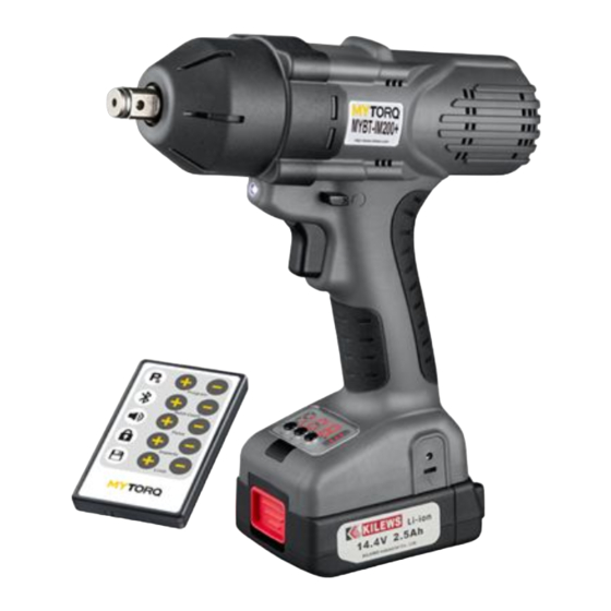
Ⅴ. Brief Function Operating (11) (12) (10) Function Name Comparison Table Number Name Number Name Start trigger Signal display light Forward and Power indicator light reverse switch level LED lighting Display panel Bit sleeve (10) Wrist strap hole Aluminum alloy (11) Bluetooth front cover... -
Page 10: Ⅵ. Function Description
Ⅵ. Function Description: 1. This Battery Screwdriver is an Impact Screwdriver. When the screw is being fastened with DaDaDa sound, it means the Battery Screwdriver continues to apply the impact until the stroke is completed, and then it will stop the impact action. (1) Start trigger: 1-1. - Page 11 (3) LED light: LED light is for auxiliary lighting, with option for on or off. Switch method: move the forward and reverse switch lever to the middle and press the trigger to turn on or off. (4) Bit sleeve operation and compatibility: Pull the cap of the Battery Screwdriver outward, and then load the BIT as shown in the following figures.
-
Page 12: Ⅵi. Instructions
3. Please operate the Battery Screwdriver carefully in accordance with the operating instructions. Do not drop or subject the Battery Screwdriver to impact. 4. When the Battery Screwdriver is running, do not change the forward and reverse switch lever to avoid system error determination. 5. - Page 13 2. KL-RC1 Remote control button icon description: Press and hold on “WS” key button till “SE1” shows up on screen. (1)[ ]after setup, illustration for remote controller buttons: Program Select Program Bluetooth Batch Count Buzzer Force Lock Impacts Save Limit 2.
- Page 14 2. KL-RC1 Remote control button icon description: Press and hold “WS” and “Res” key buttons at the same time till “SE3” appears on screen. (3)[ ]after setup, illustration for remote controller buttons: Firmware versions confirm & setting. Tightening on forward/ reverse setting Factory default setting...
-
Page 15: Operation Function Setting Description
3. Operation function setting description: Step1:Press and hold [WS/ST] button on the panel, to prompt [ SE1], then use the remote control to set up the parameters according to the function requirements. Step2:Press and hold the [number increase or decrease keys] on the remote control to speed up the value change. - Page 16 Buzzer Buzzer sound function: bun ON [Warning tone], buF OFF [Warning tone] status. Lock [program switch button] Lock function: (1) Lcn [Lock]: The program cannot be switched. (2) LcF [Unlock]: The program can be switched. Save function: (1) After the setup is completed, save and exit the setup function, and the main panel screen displays the work screen.
- Page 17 Ignore Rundown Friction: Display Panel 1. Press and hold “WS” button on the counter panel until “SE1” shows up on the screen. 2. Press “Pc” button to prompt “SE2” on the screen, and use “Batch Count” on the remote controller for setting. Botch Count 3.
-
Page 18: Function Preset
Reset to Default Settings: Display Panel 1. Press “WS+Res” button on the counter panel until “SE3” shows up on the screen. 2. Your setting will be completed when screen shows numbers of program set/ screw and hear a “Beep” sound by press “Key ”... - Page 19 Keep a rapid During fasten operation, the Red light is ON short tone until The Limit rotation number is screwdriver completes the fastening abnormal faster than the set Limit, and NOK (up) the trigger is phenomenon occurs. released Keep a short tone During fasten operation, the Red light is ON until the trigger...
-
Page 20: Other Instructions
IX. Other Instructions: 1. The optimal use of this Battery Screwdriver is no more than 8 hours per day. 2. The repair and maintenance of the Battery Screwdriver can be sent to the designated after-sales service center or the local service center via the original dealer. If the product is disassembled by the customer, our company will not be responsible for repairs. -
Page 21: Main Technical Parameters
X. Main Technical Parameters: Model (SKC-) MYBT-IM100+ MYBT-IM70+ MYBT-IM50+ Input Voltage (DC) DC 14.4V DC 14.4V DC14.4V Rotating Speed 0~2000 0~2600 0~1900 (r.p.m) Blows per minute 0~2600 0~3400 0~2500 (B.P.M) Torque (N.m) 20~100 20~70 8~50 Set IM100+& IM70+ at 80% output using M16 bolt ,KTM-IWT400 tester measured IM100+&... - Page 22 Main Technical Parameters: Model (SKC-) MYBT-IM200+ Input Voltage (DC) DC 14.4V Rotating Speed (r.p.m) 0~1700 Blows per minute (B.P.M) 0~2100 Torque (N.m) 24~200 Set IM200+ at 80% output using M20 bolt, KTM-IWT400 Torque accuracy (%) tester measured IM200+ torque accuracy is ±8~10% KTM-IWT400 apply for testing M12、M14、M16、M20 bolts Torque Tester Bolt size...
Need help?
Do you have a question about the MYBT-IM200+ and is the answer not in the manual?
Questions and answers