Table of Contents
Advertisement
Quick Links
Advertisement
Table of Contents

Subscribe to Our Youtube Channel
Related Manuals for Cantek J127LH


Summary of Contents for Cantek J127LH
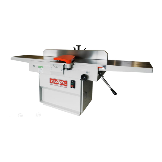
- Page 1 Operations & Parts Manual www.cantekamerica.com J127LH HEAVY DUTY 12” JOINTER Please ensure you have your serial number available when contacting us for parts or service. Cantek America Inc. | 1.888.982.2683 | Parts: sales@cantekamerica.com | Service: service@cantekamerica.com...
-
Page 2: Table Of Contents
TABLE OF CONTENTS SAFETY: ..................................1 General Rules ..................................1 Specific Rules SPECIFICATIONS ................................2 RECEIVING THE JOINTER ............................. 3 INSTALLATION & ASSEMBLY ............................. 3 ................................. 3 Fence Installation ................................3 Drive Belt Adjustment ................................3 Electrical Connection ADJUSTMENTS: ................................. 3 Replacing Knives ............................. -
Page 3: General Rules
sure the starter is in "OFF"position before connecting power to △ machine. SAFETY: General Rules △ SAFETY: Specific Rules READ THE MANUAL: Always read the owner's m anual carefully before attempting to use the machine knows the limitation READ THE MANUAL: and hazards associated with its use. -
Page 4: Specifications
NOTE: At certain time it may be necessary to plane against the NOTE: At all times hold the stock firmly. grain when working with swirl grain wood burls. With this type IF YOU ARE NOT thoroughly familiar with the operation of work the operator must use a lesser depth of cut and slow rate feed. -
Page 5: Receiving The Jointer
RECEIVING THE JOINTER Carefully unpack the jointer and all loose items from the wood crate and inspect for damage. Any damage should be reported to your distributor and shipping agent immediately. Before proceeding further, read your manual thoroughly to familiarize yourself with proper assembly, set-up, maintenance, safety and operating proced- ure. -
Page 6: Setting Knives & Outfeed Table
indicator should read between .025 and .050 as shown in Fig. 7b. If the indicator reads outside of this range, loosen the setscrew in the side of the gauge and adjust the indicator so that it will read within the range above. Zero the indicator as shown in Fig. -
Page 7: Infeed Table Adjustment
Adjust the blade within the cutterhead.Watch the pointer on As a final check of the outfeed table adjustment.Run a piece of the Model 150 gauge. The pointer will begin moving toward wood slowly over the knives for 6 to 8 inches; it should rest firmly "0". -
Page 8: Operation Instruction
JOINTING SHORT OR THIN WORK When jointing short or thin piece, use a push block to eliminate all danger to the hands. Two types are shown in Fig. 13.and are easily made from scrap material. Fig. 12 To move the fence forward or backward across the table, loosen lock handle (E), then turn knob (F). -
Page 9: Beveling
BEVELING WHETTING KNIVES To cut a bevel, lock the fence at the required angle and run the Disconnect the machine from power source. work across the knives while keeping it firmly against the fence and Use a fine carborundum stone. Cover it partly with paper as tables. -
Page 10: Trouble Shooting
TROUBLE SHOOTING TROUBLE POSSIBLE CAUSE REMEDY Raise outfeed table until it aligns with tip of Finished stock is concave on the end Knife is higher than outfeed table. knife. Raise outfeed table until it aligns with tip of Back end of stock is thicker than front end. Knife is higher than outfeed table. -
Page 11: Parts Lists & Exploded Views: Base
PARTS LIST: Base PARTNO. DESCRIPTION Q"TY C002011 Stand S282052 Washer, Φ3/8" S284023 Spring Washer, Φ3/8" S100002 Hex. Head Screw,Φ3/8"-16NC C074013 Cover, Dust Chute S239003 Screw, Dust Chute,Φ3/16"-24NC T004014 Assembly, Motor Pulley, 3HP T004041 Assembly, Motor Pulley, 5HP C022027 Plate, Switch P074013P18 Contactor, 1PH P074011E11G... -
Page 13: Work Table
PARTS LIST: Work Table PARTNO. DESCRIPTION Q” TY C004014 Base, Table C048014 Table Raising Link Bar, front C017026 Bracket S284023 Spring Washer, Φ3/8" S186006 Hex. Socket Head Screw, Φ3/8"-16NC P051003 Bushing C015052 Support P051001 Bushing C047015 Axis, Pivot C034122 Elevation Fix Bolt S282054 Washer, Φ1/2"... - Page 14 C070005 Indicator P108116 Plate, Measure S239003 Round Head Screw, Φ3/16"-24NC S196004 Fixed Screw, Φ3/8"-16NC S196003 Fixed Screw, Φ3/8"-16NC S273089 Nut, Φ1/4"-20NC S213008 Fixed Screw, M8-P1.25 P105105 Sticker, Warning P105104 Sticker, Warning...
-
Page 15: 3Hp/5Hp Motor Pulley
PARTS LIST: T004014 3HP Motor Pulley Assembly PARTNO. DESCRIPTION Q” TY P041205R Motor, 3HP/3PH P040205R Motor, 3HP/1PH C064038 Pulley, 50HZ C064019 Pulley, 60HZ S214013 Fixed Screw, M10-P1.5 C063054 Bracket, Motor S282011 Washer, M10 S284008 Spring Washer, M10 S137040 Hex. Head Screw, M10-P1.5 S273010R Nut, M10-P1.5 C015033... - Page 16 PARTS LIST: T004041 5HP Motor Pulley Assembly PARTNO. DESCRIPTION Q” TY P041206R Motor, 5HP/3PH P040206R Motor, 5HP/1PH C064039 Pulley, 50HZ C064040 Pulley, 60HZ S214013 Fixed Screw, M10-P1.5 C063054 Bracket, Motor S282011 Washer, M10 S284008 Spring Washer, M10 S137045 Hex. Head Screw, M10-P1.5 S273010R Nut, M10-P1.5 C015033...
- Page 17 PARTS LIST: T075007 Switch Plate Set PARTNO. DESCRIPTION Q"TY Cover C085048 Button, Green P082710 Stop Botton, Red P082711...
-
Page 18: Guard
PARTS LIST: T025016 Guard PARTNO. DESCRIPTION Q” TY C017027 Ledge, Table C075017 Guard C046025 Shaft C060018 Spring C051033 Collor-Guard S194006 Fixed Screw, Φ1/4"-20NC S273089 Nut, Φ1/4"-20NC P031010 Knob S284023 Spring Washer, Φ3/8" S186006 Hex. Socket Head Screw, Φ3/8"-16NC... - Page 19 PARTS LIST: T001008 Cutterhead Assembly PARTNO. DESCRIPTION Q” TY C011004 Cutterhaed C009024 Support, Bearing (LH) S026204ZZ Bearing, 6204ZZ C009025 Support, Bearing(RH) S026206ZZ Bearing, 6206ZZ C053071 Washer S136020 Hex. Head Screw, M8-P1.25 C010007 Support,Cover (LH) C010008 Support, Cover (RH) S201020 Hex. Socket Head Screw, M6-P1.0 C064020 Pulley S003178...
- Page 20 PARTS LIST: T001050 HelicalCutterhead Assembly PARTNO. DESCRIPTION Q” TY P052006 HelicalCutterhaed C009024 Support, Bearing (LH) S026204ZZ Bearing, 6204ZZ C009025 Support, Bearing(RH) S026206ZZ Bearing, 6206ZZ C053071 Washer S136620 Hex. Head Screw, M8-P1.25 C010007 Support,Cover (LH) C010008 Support, Cover (RH) S201020 Hex. Socket Head Screw, M6-P1.0 C064020 Pulley S003178...
-
Page 21: Fence
PARTS LIST: Fence PARTNO. DESCRIPTION Q” TY C015039 Support, Fence C015034 Bracket C032003 Column, Gear C051028 Fixed Collar S199016 Hex. Socket Head Screw, M4-P0.7 C075014 Guard, Cutterhead S233010 Round Head Screw, M6-P1.0 S282011 Washer, M10 S284008 Spring Washer, M10 S203030 Hex. - Page 22 S284007 Spring Washer, M8 S136025 Hex. Head Screw, M8-P1.25 S136040 Hex. Head Screw, M8-P1.25 S212012 Fixed Screw, M6-P1.0 S273042 Nut, M10-P1.5...
- Page 23 PARTS LIST: T027012 Tool Box PARTNO. DESCRIPTION Q"TY S296008 Allen Wrench,M8 S296009 Allen Wrench,M10 S290071 Open End Wrench,10x12 S290073 Open End Wrench,12x14 S290074 Open End Wrench,17x19 S296004 Allen Wrench,M3 S296006 Allen Wrench,M5 S296007 Allen Wrench,M6 P031015 Plastic handle S292304 T-Type Allen Wrench,4.0mm...
-
Page 24: Electrical Schenatic
ELECTRICAL SCHENATIC...
Need help?
Do you have a question about the J127LH and is the answer not in the manual?
Questions and answers