
Related Manuals for Lechler 5TM Series

Summary of Contents for Lechler 5TM Series
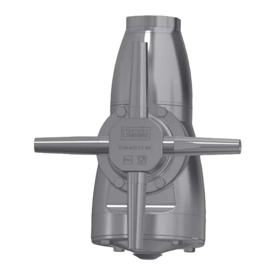
- Page 1 Maintenance Instructions High impact tank cleaning machine Series 5TM Maintenance Instructions...
-
Page 2: Table Of Contents
CONTENT Content Page Introduction Exploded view 5TM Gearbox assembly Parts List 7 – 10 Maintenance 1 Maintenance 2 Disassembly Cover Pos. 35 Cover Pos. 34 Connection piece Bearing pos. 32 - for shaft pos. 9 16-17 Impeller 18-19 Gear frame Shaft pos. - Page 3 Shaft pos. 9 Impeller Gear frame Bearing pos. 32 for shaft pos. 9 Cover pos. 34 Connection piece Cover pos. 35 Checklist before commissioning after maintenance...
-
Page 4: Introduction
Maintenance 1 1000 Maintenance 2 1500 Maintenance 1 2000 Maintenance 2 Only use original Lechler parts for maintenance. All cylinder and hexagon head screws are se- cured with thread lock lacquer. For use in the food industry we recommend LOCTITE ®... -
Page 7: Parts List
PARTS LIST Part Number Description Material Machine (Nos) 5TM.000.1Y.02.AN.0 Connection Piece: 316L SS G 1” ISO 228 (F) 5TM.000.1Y.02.AM.0 Connection Piece: 316L SS G 1” ISO 228 (M) 5TM.000.1Y.02.AS.0 Connection Piece: 316L SS G 1 ½” ISO 228 (F) 5TM.000.1Y.02.AR.0 Connection Piece: 316L SS G 1 ½”... - Page 8 Material Part Number Description Machine Shaft 5TC.000.1Y.04.00.0 316L SS 5TM.000.R6.4V.R0.0 Ball 302 SS 5TM.000.C9.26.R0.0 Bearing Ring 316L SS Hardened] 5TC.000.1Y.05.00.0 Impeller 316L SS 5TM.000.T7.09.00.0 Bushing PEEK Shaft 5TC.000.1Y.11.00.0 316L SS 5TM.000.1Y.12.13.0 Spur Gear 316L SS 5TC.000.1Y.14.00.0 Pinion Shaft 316L SS 5TM.000.T7.15.C0.0 Collar Bushing PEEK...
- Page 9 Material Part Number Description Machine 5TC.000.1C.02.FR.0 Cylinder Head Screw 304 SS 5TC.000.1Y.19.00.0 Washer 316L SS 5TC.000.1Y.21.00.0 Cover 316L SS 5TC.000.55.21.G0.1 Gasket PTFE 5TC.000.1C.21.H0.0 Hexagon Head Screw 304 SS 5TC.000.1Y.22.00.0 Bevel Gear 316L SS 5TM.0XX.1Y.23.YS.0 *XX = Nozzle opening [= 316L SS 04 [5TM.4XX] 06, 07, 08, 09, 10 mm] 02 [5TM.2XX]...
- Page 10 Part Number Description Material Machine (Nos) 5TC.000.C9.26.R0.0 Bearing Ring 316L SS Hardened 5TM.000.1Y.27.00.0 Nozzle Body 316L SS 5TC.000.C9.27.U0.0 Bushing – Upper 316L SS Hardened 5TM.000.C9.27.L0.0 Bushing – Lower 316L SS Hardened 5TC.000.C9.27.H0.0 Bushing 316L SS Hardened 5TM.000.17.28.S0.0 [SS-316] Worm Bearing 5TM.000.T7.29.C0.0 PEEK Gear frame...
-
Page 11: Maintenance 1
MAINTENANCE 1 It is recommended to perform Maintenance 1 every 500 operating hours. For this purpose, utilize Spare parts package 1, consisting of: Spare parts package 1 Pos. spare Description Quantity Product number Ordering number parts list Cylinder head screw 6 pieces 5TC.000.1C.02.FS.0 3/16“... - Page 12 MAINTENANCE 2 It is recommended to perform Maintenance 2 every 1.000 operating hours. For this purpose, ultilze Spare parts package 2, consisting of: Spare parts package 2 Pos. spare Description Quantity Product number Ordering number parts list Cylinder head screw 6 pieces 5TC.000.1C.02.FS.0 3/16“...
-
Page 13: Disassembly
DISASSEMBLY During maintenance, a visual inspection of all parts should always be carried out. The components that require special attention are described in the following steps. The following tools are required for maintenance:: Allen wrench with ball head 4 mm „... - Page 14 Cover Pos. 34 Loosen the four cylinder head screws and remove the cover 5TC.000.1Y.31.00.0 (item 34). „ Information on bearing (pos. 32) on the shaft (pos. 9) To loosen the screw that fixes the bearing 5TM.000.T7.29.C0.0 (item 32) to the shaft (item 9), it is necessary to lock the impeller 5TC.000.1Y.05.00.0 (pos.
-
Page 15: Connection Piece
Connection piece For the 5TM there are different connection pieces (female thread, male thread, flange connection- see pos. 1 spare parts list). All connection pieces can be loosened with a 4 mm allen wrench. Depending on the type of connection, a hexagon socket wrench with ball head may be required. Unscrew cylinder head screws ( 5TC.000.1C.02.FS.0 / if necessary 5TC.000.1C.02.FR.0 ) „... -
Page 16: Bearing Pos. 32 - For Shaft Pos
Bearing pos. 32 – for shaft pos. 9 Size 5TM.2XX and 5TM.40X: Size 5TM.410.XX.XX.XX.X: „ „ From the connection side push a rod With the connection piece removed, insert „ „ made of brass or plastic (diameter approx. a rod made of brass or plastic (diameter Ø... - Page 17 Note: Inspection of the worm gear during maintenance 1 During maintenance 1, the worm gear should be checked for wear. This can be done by a visual inspection. In case of premature wear, caused by harsh operating conditions, the shaft pos.
-
Page 18: Impeller
Impeller To loosen the screw that fixes the impeller 5TC.000.1Y.05.00.0 (item 7) it is necessary to lock the impeller with a round rod (e.g. made of brass or a plastic). Lock impeller „ Loosen hexagon socket screw and „ remove together with the washer. Remove impeller „... -
Page 19: Gear Frame
Hint: It is possible that the impeller can not easily detached from the shaft. In this case the cylinder head screw (without washer) can be screwed in for approx. 3 rotations in the shaft. By striking on the head of the screw gently with a rubber mallet, the impeller can be detached from the shaft. -
Page 20: Shaft Pos. 9
Hint: Before removing the gear frame, press the shaft towards the connection side. „ Shaft pos. 9 Remove the shaft upwards. „... - Page 21 Note: Inspection of shaft pos. 9 in course of maintenance 1 During the course of maintenance 1, the shaft pos. 9 should be checked for wear. With premature wear, caused by correspondingly harsh operating conditions, it is recomended to run the maintenance 2. The wear on the shaft pos.
-
Page 22: Spur Gear
Spur gear Attention: Make sure that the nozzle body pos. 27 is positioned on a straight and firm base. Loosen and remove the six cylinder screws of the 5TM.000.1Y.12.13.0 spur gear (pos. 10). „ For this purpose, the spur gear should be fixed with a suitable bolt (e.g. made of brass or plastic) and secured to prevent rotation. -
Page 23: Bushing Pos. 8
Then lift the nozzle body. The shaft remains 5TC.000.1Y.04.00.0 (pos. 4) with the ball „ bearing on the base. Attention! The shaft should not be lifted or moved, otherwise the ball bearing with „ the 58 balls will come loose. Bushing pos. -
Page 24: Bearing On Shaft - Pos. 4
Bearing on shaft – pos. 4 Remove bearing consisting of 2x bearing ring 5TM.000.C9.26.R0.0 (pos. 6) and 58 x ball „ 5TM.000.R6.4V.R0.0 (pos. 5). Bearing pos. 25 + 26 in nozzle body Remove ball bearing 5TC.000.2R.26.BR.1 (pos. 25) and bearing ring 5TC.000.C9.26.R0.0 „... -
Page 25: Gearbox Assembly
Gearbox assembly Worm Loosen the cover 5TC.000.1Y.31.00.0 (pos. 34) with the four cylinder screws and remove. „ Remove the cylinder screw including the washer of the worm (pos. 31). To do this, hold up „ with an open-end wrench (wrench size 10) at the flats of the worm. Alternatively, a suitable pair of pliers can be used. - Page 26 Remove bearing 5TM.000.T7.29.C0.0 Remove worm 5TM.000.17.28.S0.0 (pos. „ „ (pos. 32) 31) and at the same time pull out the worm gear and the spacer 5TM.000.T7.16.PS.0 (pos. 13). Remove collar bushing „ 5TM.000.T7.15.C0.0 (pos. 12).
- Page 27 Pinion shaft To remove the pinion shaft 5TC.000.1Y.14.00.0 (pos. 11), place the gear wheel in soft „ protective jaws clamped in a vice. Then loosen and remove the socket head screw including washer. Pull out the pinion shaft 5TC.000.1Y.00.0 „ and at the same time remove the worm gear and the spacer 5TM.000.T7.16.PS.0 (pos.
- Page 28 Remove sleeve 5TC.000.1Y.17.00.0 (pos. 14) „ Remove collar bushings „ 5TM.000.T7.15.C0.0 (pos. 12).
-
Page 29: Nozzle Seat Assembly
Nozzle seat assembly To remove the nozzle seat 5TM.000.1Y.24.04.1 (pos. 23) from the nozzle body „ 5TM.000.1Y.27.00.0 (pos. 27), the 6 hexagon head screws must be removed. Remove grub screw 5TC.000.1Y.24.S0.0 (pos. 24) at the nozzle seat. „... - Page 30 Clamp one nozzle 5TM.0XX.1Y.23.YS.0 (pos. 21) in the vice and loosen the „ 5TC.0001Y.24.C0.0 connecting piece (pos. 22) with a face wrench (bolt diameter 5.0 mm). Remove bevel gear 5TC.000.1Y.22.00.0 (pos. 20). „ Remove upper bearing ring 5TC.000.C9.26.R0.0 ( pos. 26), ball bearing „...
-
Page 31: Inspection
Remove gasket 5TC.000.55.21.G0.1 (pos. 18). „ Inspection Inspect for foreign objects that may have entered the interior of the high impact tank cleaning machine. Foreign objects may adversely affect the life of the gearbox and turbine. Worm gear During maintenance 1, the worm gear should be visually inspected for wear. See note Inspection of worm gear on page 67. -
Page 32: Nozzle Seat Assembly
Nozzle seat assembly For the installation of the assembly of the nozzle seat it is helpful, as shown in the picture „ above to clamp one nozzle 5TM.009.1Y.23.YS.0 ( pos. 21 ) in the vice. Insert the seal in the nozzle seat 5TC.000.55.21.G0.1 (pos. 18). „... - Page 33 Insert bevel gear 5TC.000.1Y.22.00.0 (pos. 20). „ Place the connecting piece on the nozzle seat by hand and screw it in. Use a face wrench „ (pin diameter 5.0 mm) to tighten the 5TC.0001Y.24.C0.0 connecting piece (pos. 22).
- Page 34 Attention: Important step, do not forget! „ The grub screw is used to secure the threaded connection between nozzle seat and the „ connecting piece against loosening. Screw the grub screw 5TC.000.1Y.24.S0.0 (pos. 24) into the nozzle seat. Push the nozzle seat assembly onto the nozzle body and screw it evenly and crosswise to the „...
-
Page 35: Bearing Pos. 25 + 26 In Nozzle Body
Bearing Pos. 25 + 26 in the nozzle body Insert bearing ring 5TC.000.C9.26.R0.0 (pos. 26) and ball bearing 5TC.000.2R.26.BR.1 „ (pos. 25). Bearing on shaft Pos. 4 Insert bearing consisting of 2 x bearing ring 5TM.000.C9.26.R0.0 (pos. 6) and 58 x ball „... -
Page 36: Bushing Pos. 8
Bushing Pos. 8 Insert the bushing 5TM.000.T7.09.00.0 (pos. 8) with the small diameter facing down into the „ shaft 5TC.000.1Y.04.00.0 (pos. 4). Spur gear The bearing ring 5TC.000.C9.26.R0.0 (pos. 26) can be pushed onto the spur gear by hand. „ Make sure that the bearing ring fits evenly. - Page 37 Place nozzle body back on the shaft 5TC.000.1Y.04.00.0 (pos. 4). „ The spur gear with the pressed-on bearing „ ring can now be inserted. Make sure that the side of the spur gear is facing upwards and the bearing ring is facing downwards towards the bearing.
-
Page 38: Gearbox Assembly
Screw in the six hexagon socket screws „ of the spur gear and tighten them evenly and crosswise (approx. 3 – 4 Nm). For this purpose, the spur gear should be secured to prevent rotation with a suitable bolt (e.g. made of brass or plastic). Securely lodge the bolt between the spur gear and nozzle body. - Page 39 Position the worm gear and the spacer „ 5TM.000.T7.16.PS.0 (pos. 13). Next, insert the pinion shaft 5TC.000.1Y.14.00.0 (pos. 11) with a rotary motion and hold on the worm gear. This ensures that the 2 flats of the pinion shaft snaps into the worm gear.
- Page 40 Clamp the pinion shaft gear in a vice with soft protective jaws and tighten the cylinder head „ screw 5TC.000.1C.02.FR.0 (pos. 15) incl. washer 5TC.000.1Y.19.00.0 (pos. 16) (approx. 3 – 4 Nm). Worm Insert collar bushing 5TM.000.T7.15.C0.0 (pos. 12). „...
- Page 41 Position worm gear from Set 5TM.000.T7.16.PS.0 (pos. 13) and then insert worm „ 5TM.000.17.28.S0.0 (pos. 31) with a rotary motion and hold on the worm gear. This ensures that the 2-flats of the worm snaps into the worm gear. Insert spacer from set 5TM.000.T7.16.PS.0 (pos. 13). „...
- Page 42 Side shoulder inward Side with grooves Insert bearing 5TM.000.T7.29.C0.0 (pos. 32). Make sure that the side with shoulder at the „ bearing points towards the screw / washer. Screw the cylinder head screw 5TC.000.1C.02.FR.0 (pos. 15) including washer „ 5TC.000.1Y.19.00.0 (pos. 16) into the worm. To do this, hold up with an open-end wrench (wrench size 10) at the flats of the worm.
- Page 43 Cover tightened evenly Cover unevenly tightened Side without shoulder inwards Side with shoulder inwards Tighten the cover 5TC.000.1Y.31.00.0 (pos. 34) (side with shoulder facing the bearing) with „ the four socket head screws 5TC.000.1C.02.FR.0 (pos. 15). Make sure that the screws are tightened evenly stepwise and crosswise up to a torque of 3 –...
-
Page 44: Shaft Pos. 9
Shaft Pos. 9 Insert shaft 5TC.000.1Y.11.00.0 (Pos. 9) into bushing 5TM.000.T7.09.00.0 (pos. 8). Thereby „ the worm on the shaft should face upwards. Impeller Mount the impeller 5TC.000.1Y.05.00.0 (pos. 7) with the pocket facing to the shaft (pos. 9). „ Position the pocket precisely on the 2 flats of the shaft. -
Page 45: Gear Frame
Gear frame Put the 5TM on the connection side. This causes that the shaft (pos. 9) will slide a little bit „ downwards and the pre-assembled gearbox can be easily inserted. Tighten the gear frame by using the 4 cylinder head screws evenly and crosswise „... -
Page 46: Bearing Pos. 32 For Shaft Pos. 9
Bearing pos. 32 for shaft pos. 9 When assembling the bearing 5TM.000.T7.29.C0.0 (pos. 32), make sure that the shoulder „ on the bearing points in the direction of the screw / washer. Side shoulder inward Side with grooves To fix the bearing 5TM.000.T7.29.C0.0 „... -
Page 47: Cover Pos. 34
Cover Pos. 34 Tighten the cover 5TC.000.1Y.31.00.0 (pos. 34) (side without shoulder faces upwards) with „ the four cylinder screws 5TC.000.1C.02.FR.0 (pos. 15). The following must be observed ensure that the screws are tightened evenly stepwise and crosswise up to a torque of 3 –... -
Page 48: Connection Piece
Connection piece Place the connection piece (pos. 1) and tighten it evenly and crosswise (approx. 3 – 4 Nm) by „ using the 6 cylinder head screws 5TC.000.1C.02.FS.0 (if necessary 5TC.000.1C.02.FR.0). Cover Pos. 35 Place the cover 5TM.000.1Y.33.C0.0 (pos. 35) on the 5TM and tighten it evenly and cross- „... -
Page 49: Checklist Before Commissioning After Maintenance
Checklist before commissioning after maintenance After the maintenance has been carried out, the following points should be checked before recommissioning: All cylinder and hexagon head screws are coated with thread lock lacquer (considering for „ drying time). Screws on the covers, pos. 34, are tightened evenly and crosswise. „... - Page 50 LECHLER WORLDWIDE LECHLER WORLDWIDE World Headquarters Lechler Companies Sales Offices Lechler, Inc.· Precision Nozzles · Nozzle Systems 445 Kautz Rd. St. Charles, IL 60174 · Phone: 800-777-2926 · Fax: 630-377-6657 info@lechlerusa.com · www.lechlerusa.com...
Need help?
Do you have a question about the 5TM Series and is the answer not in the manual?
Questions and answers