Table of Contents
Advertisement
Quick Links
Introduction
This getting started guide for the OSD3358-SM-RED board is intended to serve as a quick
reference to getting the OSD3358-SM RED board up and running.
This document will be updated as required to improve or add information. Please make sure to
look for updates and sign up for document change notifications on
get up to date info.
Revision History
Revision
Initial Revision
Notice:
The information provided within this document is for informational use only. Octavo
Systems provides no guarantees or warranty to the information contained.
OSD3358-SM-RED - Getting Started Guide
Details
Octavo Systems LLC
Copyright 2017
Octavo Systems website
Date
9-7-2017
Rev. 1.0 9/7/2017
to
Author
Neeraj Dantu
Advertisement
Table of Contents

Related Manuals for Octavo OSD3358-SM-RED


Summary of Contents for Octavo OSD3358-SM-RED
- Page 1 Rev. 1.0 9/7/2017 Introduction This getting started guide for the OSD3358-SM-RED board is intended to serve as a quick reference to getting the OSD3358-SM RED board up and running. This document will be updated as required to improve or add information. Please make sure to...
-
Page 2: Table Of Contents
Unboxing your board .................. 4 Powering the OSD3358-SM-RED..............6 Power up procedure ................6 OSD3358-SM-RED Use Cases ................. 10 Standalone boot up ................10 Booting as USB client connected to a computer/laptop ........16 Boot messages through UART ..............20 User LEDs .................. -
Page 3: Features
OSD3358-SM-RED Getting Started Guide Rev. 1.0 9/7/2017 1 Features The following figure highlights the features of the OSD3358-SM-RED platform (RED Board) and where they are located on the board. Figure 1: OSD3358-SM-RED board features Octavo Systems LLC Copyright 2017... -
Page 4: Unboxing Your Board
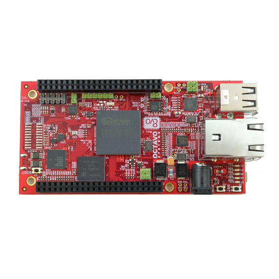
OSD3358-SM-RED Getting Started Guide Rev. 1.0 9/7/2017 2 Unboxing your board The contents of the OSD3358-SM-RED platform are listed below: 1. OSD3358-SM-RED Figure 2: OSD3358-SM-RED 2. Micro-USB to USB cable Figure 3: USB cable Octavo Systems LLC Copyright 2017... - Page 5 OSD3358-SM-RED Getting Started Guide Rev. 1.0 9/7/2017 3. Getting started card Figure 4: OSD3358-SM-RED platform getting started card Octavo Systems LLC Copyright 2017...
-
Page 6: Powering The Osd3358-Sm-Red
OSD3358-SM-RED Getting Started Guide Rev. 1.0 9/7/2017 3 Powering the OSD3358-SM-RED Figure 5 shows the OSD3358-SM-RED and its power inputs. The board can be powered through any of three inputs: a. Micro-USB cable connected to the micro-USB port b. 5V AC adapter connected to the 2.5 mm x 5.5 mm barrel jack c. - Page 7 OSD3358-SM-RED Getting Started Guide Rev. 1.0 9/7/2017 1. Connect your preferred power source: a. USB: i. Connect the micro-USB side of the USB cable to the micro-USB port X1 ii. Connect the USB side to one of the USB ports on a laptop/computer or other USB power source.
- Page 8 Figure 7: Powering the RED board using an AC-DC adapter c. Battery input terminals: i. Connect the battery input terminals to the battery terminals as shown below. Figure 8: OSD3358-SM-RED battery connections (back-side of board) Octavo Systems LLC Copyright 2017...
- Page 9 OSD3358-SM-RED Getting Started Guide Rev. 1.0 9/7/2017 NOTE: Notes on connecting the PMIC_TS input of the SiP can be found in "Battery pack temperature monitoring" section of the TPS65217C PMIC datasheet. If the battery does not have a temperature output, the battery temperature monitoring mechanism of the PMIC can be bypassed by connecting a 10KOhm resister between PMIC_TS (TP7) of the board and GND.
-
Page 10: Osd3358-Sm-Red Use Cases
OSD3358-SM-RED Getting Started Guide Rev. 1.0 9/7/2017 4 OSD3358-SM-RED Use Cases The OSD3358-SM-RED Platform can be used in 3 different modes. A description of each mode and instructions on how to set up each mode is described below. 4.1 Standalone boot up The board can be used as a standalone platform for software development. - Page 11 OSD3358-SM-RED Getting Started Guide Rev. 1.0 9/7/2017 The following steps describe the procedure to setup the board as a standalone software development tool. 1. Connect the micro HDMI connector of the HDMI cable to X6 connector on board. 2. Connect the HDMI connector of the HDMI cable into the monitor. HDMI to DVI-D convertor may be necessary if the monitor only has a DVI-D input.
- Page 12 OSD3358-SM-RED Getting Started Guide Rev. 1.0 9/7/2017 3. Connect the wired/wireless USB keyboard and mouse inputs to any of the four USB ports available on X4 and X5 connectors of the board. Figure 12: Wireless adapter for keyboard and mouse plugged in to RED board...
- Page 13 OSD3358-SM-RED Getting Started Guide Rev. 1.0 9/7/2017 4. If internet connectivity is required: a. a WiFi-USB adapter can be plugged into one of the available USB ports on X4 or X5 connector. A list of compatible adapters can be found at http://www.elinux.org/Beagleboard:BeagleBoneBlack#WIFI_Adapters...
- Page 14 Figure 14: AC-DC adapter plugged in to RED board 6. The board will go through the default boot up process 7. After the board boots up, the monitor screen should show a Linux desktop environment as shown below. Figure 15: OSD3358-SM-RED desktop environment Octavo Systems LLC Copyright 2017...
- Page 15 OSD3358-SM-RED Getting Started Guide Rev. 1.0 9/7/2017 8. Click on the Start>System Tools>Q Terminal to open a command terminal. Figure 16: Shell command terminal on desktop environment Octavo Systems LLC Copyright 2017...
-
Page 16: Booting As Usb Client Connected To A Computer/Laptop
4.2 Booting as USB client connected to a computer/laptop The OSD3358-SM-RED platform can also be powered using a computer/laptop’s USB port. The micro-USB to USB cable provided in the box can be used to connect the RED board to a computer/laptop. - Page 17 OSD3358-SM-RED Getting Started Guide Rev. 1.0 9/7/2017 3. Wait for the board to show up as a mass storage device on the computer/laptop Figure 18: OSD3358-SM-RED USB mass storage filesystem window Octavo Systems LLC Copyright 2017...
- Page 18 4. Open a browser (Firefox/Chrome) and access the url: http://192.168.7.2 . The webpage hosted on the webserver of the board should indicate that the board is connected as shown below. Figure 19: OSD3358-SM-RED home webpage indicating a connection to the board Octavo Systems LLC Copyright 2017...
- Page 19 OSD3358-SM-RED Getting Started Guide Rev. 1.0 9/7/2017 5. Access the cloud9 IDE through the url: http://192.168.7.2:3000/ . Cloud9 IDE is an opensource web based development environment supporting several languages. The environment should look like the following figure with workspace containing examples that can be executed.
-
Page 20: Boot Messages Through Uart
Rev. 1.0 9/7/2017 4.3 Boot messages through UART The processor on the OSD3358-SM-RED platform sends boot messages through the UART0 port, J3. This is useful in embedded Linux development or if there are boot problems to verify proper initialization of all components on the board. After boot, the UART0 port will function as a Linux terminal. - Page 21 OSD3358-SM-RED Getting Started Guide Rev. 1.0 9/7/2017 2. Connect the USB side of the adapter to the computer/laptop Figure 22: UART-USB adapter plugged in to the computer 3. Check which COM port of the computer/laptop the adapter is connected to using the device manager.
- Page 22 OSD3358-SM-RED Getting Started Guide Rev. 1.0 9/7/2017 4. Open a serial console (opensource applications like Putty come with one). Select the serial communication option and specify the port and speed of the protocol as shown below and click on open.
- Page 23 OSD3358-SM-RED Getting Started Guide Rev. 1.0 9/7/2017 5. After a new serial console is open, connect the board to a power supply through one of the three power inputs of the board. The boot messages should begin to scroll on the console.
-
Page 24: User Leds
OSD3358-SM-RED Getting Started Guide Rev. 1.0 9/7/2017 4.4 User LEDs While the LEDs D4 through D7 can be controlled as desired, they have the following standard function when the system is booted. • D4: Activity indicator for MMC1 interface (eMMC) •... -
Page 25: Getting Started With The Software
5 Getting started with the software 5.1 Onboard sensor interfacing There are several sensors on OSD3358-SM-RED board. The board is equipped with a software library and examples to interface with the sensors. The library package ‘Redperipherallib’ is pre- installed on Linux and allows commands line access to these components on the board. The Roboticscape library ( http://strawsondesign.com/#!manual-install... -
Page 26: Accessing Peripherals Using Shell Terminal
OSD3358-SM-RED Getting Started Guide Rev. 1.0 9/7/2017 5.1.1 Accessing peripherals using shell terminal The RED peripheral library facilitates command line access to board features. Some of the relevant commands, options and output formats to access on board sensor data are given below. - Page 27 OSD3358-SM-RED Getting Started Guide Rev. 1.0 9/7/2017 3. rc_check_model Function: This command returns the board name that it is currently running on Options: None Results: root@beaglebone:~$ rc_check_model Currently running on a: OCT_OSD3358-SM-RED 4. rc_test_barometer Function: This command runs a test on the barometer and returns the temperature,...
- Page 28 OSD3358-SM-RED Getting Started Guide Rev. 1.0 9/7/2017 6. rc_test_tmp Function: This command tests the temperature sensor and returns the temperature value on channel 8 Options: None Results: root@beaglebone:~$ rc_test_tmp temperature sensor read value in celsius: 28.750000 7. rc_version Function: This command returns the version of the peripheral library being run on the...
Need help?
Do you have a question about the OSD3358-SM-RED and is the answer not in the manual?
Questions and answers