Table of Contents
Advertisement
Quick Links
Introduction
This User Guide (UG) for the OSD3358-SM-RED platform is intended to serve as a resource to
find information regarding design and usage of the hardware and software aspects of the board.
It will cover topics ranging from getting started with the platform to using different sensors and
peripherals that are present on board.
This document will be updated as required to improve or add information. Please make sure to
look for updates and sign up for document change notifications on
get up to date info.
Some relevant resources for support and development are given below:
•
OSD3358-SM-RED board design files:
https://octavosystems.com/files/osd3358-sm-red-eagle-files/
•
Sign up for OSD3358-SM-RED latest software updates:
https://octavosystems.com/doc-change-signup/
•
OSD3358-SM datasheet:
https://octavosystems.com/docs/osd335x-sm-datasheet/
•
OSD3358-SM RED platform getting started guide:
https://octavosystems.com/docs/osd3358-sm-red-quick-start-guide/
•
OSD3358-SM Application notes:
a. OSD335x-SM layout guide:
https://octavosystems.com/app_notes/osd335x-sm-layout-guide/
b. OSD335x Family Pin Assignments Compared to AM335x:
https://octavosystems.com/app_notes/osd335x-family-pin-assignments/
Notice:
The information provided within this document is for informational use only. Octavo
Systems provides no guarantees or warranty to the information contained.
OSD3358-SM-RED – User Guide
Octavo Systems LLC
Copyright 2017
Rev. 1.0 9/19/2017
Octavo Systems website
to
Advertisement
Table of Contents

Subscribe to Our Youtube Channel
Related Manuals for Octavo OSD3358-SM-RED

Summary of Contents for Octavo OSD3358-SM-RED
- Page 1 Rev. 1.0 9/19/2017 Introduction This User Guide (UG) for the OSD3358-SM-RED platform is intended to serve as a resource to find information regarding design and usage of the hardware and software aspects of the board. It will cover topics ranging from getting started with the platform to using different sensors and peripherals that are present on board.
- Page 2 OSD3358-SM-RED – User Guide Rev. 1.0 9/19/2017 Revision History Revision Details Date Author Initial draft 09-19-2017 Neeraj Dantu Octavo Systems LLC Copyright 2017...
-
Page 3: Table Of Contents
Rev. 1.0 9/19/2017 Contents Powering the OSD3358-SM-RED..............6 Power up procedure ................7 OSD3358-SM-RED Use Cases ................. 10 Standalone boot up ................10 Booting as USB client connected to a computer/laptop ........14 Boot messages through UART ..............17 User LEDs ..................21 Powering down/ power cycling ............... - Page 4 OSD3358-SM-RED – User Guide Rev. 1.0 9/19/2017 Clamping circuit ................46 Clock inputs to the processor ..............47 4.6.1 OSC0: ..................47 4.6.2 OSC1: ..................47 Boot configuration ................49 UART0 interface ................51 eMMC ..................... 52 4.10 MicroSD card slot ................53 4.11 JTAG ....................
- Page 5 OSD3358-SM-RED – User Guide Rev. 1.0 9/19/2017 Reference Documents ................76 Octavo Systems LLC Copyright 2017...
-
Page 6: Powering The Osd3358-Sm-Red
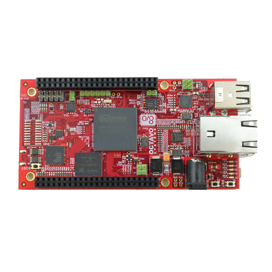
OSD3358-SM-RED – User Guide Rev. 1.0 9/19/2017 1 Powering the OSD3358-SM-RED Figure 1 shows the OSD3358-SM-RED and its power inputs. The board can be powered through any of three inputs: 1. Micro-USB cable connected to the micro-USB port 2. 5V AC adapter connected to the barrel jack 3. -
Page 7: Power Up Procedure
OSD3358-SM-RED – User Guide Rev. 1.0 9/19/2017 1.1 Power up procedure The following steps describe the power up sequence of the board when powered via USB, AC Adapter or battery inputs. 1. Connect your preferred power source: a. USB: i. Connect the micro-USB side of the USB cable to the micro-USB port X1 ii. - Page 8 Figure 3: Powering the RED board using an AC-DC adapter c. Battery input terminals: i. Connect the battery input terminals to the battery terminals as shown below. Figure 4: OSD3358-SM-RED battery connections (back-side of board) Octavo Systems LLC Copyright 2017...
- Page 9 OSD3358-SM-RED – User Guide Rev. 1.0 9/19/2017 NOTE: Notes on connecting the PMIC_TS input of the SiP can be found in "Battery pack temperature monitoring" section of the TPS65217C PMIC datasheet. If the battery does not have a temperature output, the battery temperature monitoring mechanism of the PMIC can be bypassed by connecting a 10KOhm resister between PMIC_TS (TP7) of the board and GND.
-
Page 10: Osd3358-Sm-Red Use Cases
OSD3358-SM-RED – User Guide Rev. 1.0 9/19/2017 2 OSD3358-SM-RED Use Cases The OSD3358-SM-RED Platform can be used in 3 different modes. A description of each mode and instructions on how to set up each mode is described below. 2.1 Standalone boot up The board can be used as a standalone platform for software development. - Page 11 OSD3358-SM-RED – User Guide Rev. 1.0 9/19/2017 3. Connect the wired/wireless USB keyboard and mouse inputs to any of the four USB ports available on X4 and X5 connectors of the board. Figure 8: Wireless adapter for keyboard and mouse plugged in to RED board 4.
- Page 12 Figure 10: AC-DC adapter plugged in to RED board 6. The board will go through the default boot up process 7. After the board boots up, the monitor screen should show a Linux desktop environment as shown below. Figure 11: OSD3358-SM-RED desktop environment Octavo Systems LLC Copyright 2017...
- Page 13 OSD3358-SM-RED – User Guide Rev. 1.0 9/19/2017 8. Click on the Start>System Tools>Q Terminal to open up a command terminal. Figure 12: Shell command terminal on booted desktop Octavo Systems LLC Copyright 2017...
-
Page 14: Booting As Usb Client Connected To A Computer/Laptop
2.2 Booting as USB client connected to a computer/laptop The OSD3358-SM-RED platform can also be powered using a computer/laptop’s USB port. The micro-USB to USB cable provided in the box can be used to connect the RED board to a computer/laptop. - Page 15 OSD3358-SM-RED – User Guide Rev. 1.0 9/19/2017 3. Wait for the board to show up as a mass storage device on the computer/laptop Figure 14: OSD3358-SM-RED USB mass storage filesystem window Octavo Systems LLC Copyright 2017...
- Page 16 Figure 15: OSD3358-SM-RED home webpage indicating a connection to the board 5. Access the cloud9 IDE through the url: http://192.168.7.2:3000/. Cloud9 IDE is an opensource web based development environment supporting several languages.
-
Page 17: Boot Messages Through Uart
Rev. 1.0 9/19/2017 2.3 Boot messages through UART The processor on the OSD3358-SM-RED platform (RED board) sends boot messages through the UART0 port, J3. This is useful in embedded Linux development or if there are boot problems to verify proper initialization of all components on the board. After boot, the UART0 port will function as a Linux terminal. - Page 18 OSD3358-SM-RED – User Guide Rev. 1.0 9/19/2017 2. Connect the USB side of the adapter to the computer/laptop Figure 18: UART-USB adapter plugged in to the computer 3. Check which COM port of the computer/laptop the adapter is connected to using the device manager.
- Page 19 OSD3358-SM-RED – User Guide Rev. 1.0 9/19/2017 4. Open a serial console (opensource applications like Putty come with one). Select the serial communication option and specify the port and speed of the protocol as shown below and click on open.
- Page 20 OSD3358-SM-RED – User Guide Rev. 1.0 9/19/2017 5. After a new serial console is open, connect the board to a power supply through one of the three power inputs of the board. The boot messages should begin to scroll on the console.
-
Page 21: User Leds
OSD3358-SM-RED – User Guide Rev. 1.0 9/19/2017 2.4 User LEDs While the LEDs D4 through D7 can be controlled as desired, they have the following standard function when the system is booted. • D4: Activity indicator for MMC1 interface (eMMC) •... -
Page 22: Overview Of Osd3358-Sm-Red
Rev. 1.0 9/19/2017 3 Overview of OSD3358-SM-RED The OSD3358-SM-RED is a Reference, Evaluation, and Development platform for the OSD335x-SM family of devices from Octavo Systems. The OSD335x-SM integrates the AM335x processor from Texas Instruments (TI) along with the TI TPS65217C PMIC, the TI... - Page 23 OSD3358-SM-RED – User Guide Rev. 1.0 9/19/2017 The following table provides an overview of the specification of the board. Table 1: OSD3358-SM-RED specification PART PROPERTY VALUE OSD3358-512M-BSM (U1) Processor TI Sitara AM3358 ZCZ 1GHz SGX530 3D Graphics accelerator Real-time processor...
- Page 24 OSD3358-SM-RED – User Guide Rev. 1.0 9/19/2017 Package 8-pin W-PDFN TPM (U16) Part number AT97SC3205T I2C bus I2C0 I2C address 0x29 Supply voltage 3.3V Package 32-pin QFN Temperature hub (U17) Part number TMP468 Number of channels 9: 1 board monitoring channel,...
-
Page 25: Processor (U1)
3.2 Processor (U1) The OSD3358-SM-RED board uses the OSD3358-512M-BSM (U1) System-in-Package (SiP) device from Octavo Systems. The SiP package integrates TI’s AM3358 processor, TI power management system, 512MB of DDR3 memory and 4KB EEPROM in 21mm x 21mm BGA package. A list of references for each of the main components integrated in the OSD3358-SM is given below: •... -
Page 26: Pc Usb Interface (X1)
Figure 23: USB OTG port of the RED board NOTE: OSD3358-SM-RED Platform is compatible specifically with Linux images that can be installed on the boards Beaglebone Black, Beaglebone Black Wireless, Beaglebone Blue. -
Page 27: Serial Debug Interface (J3)
OSD3358-SM-RED – User Guide Rev. 1.0 9/19/2017 3.4 Serial debug interface (J3) The UART0 port of the processor is exposed as a 1x6 header J3 (shown below). This interface serves as a debug port that can be accessed via USB port of a laptop/computer using a USB to Serial interface adapter. -
Page 28: Emmc (U7)
OSD3358-SM-RED – User Guide Rev. 1.0 9/19/2017 3.5 EMMC (U7) A 16GB embedded Multi-Media Card (eMMC), U7, is connected to 8-bit wide MMC1 port of the processor (shown below). It contains the Linux image that the board will boot from by default. -
Page 29: Cape Headers (J5 & J6)
They are compatible with Beaglebone Black headers P8 & P9 (http://elinux.org/Beagleboard:Cape_Expansion_Headers) meaning capes for the Beaglebone Black are compatible and work with the OSD3358-SM-RED board. More information on these headers can be found in Section 4.22. -
Page 30: Jtag (J4)
OSD3358-SM-RED – User Guide Rev. 1.0 9/19/2017 3.7 JTAG (J4) A 20 pin CTI JTAG footprint J4 (shown below) is exposed for mounting a JTAG header on the board. This port can be used for software development and debug by connecting to the board through a JTAG emulator. -
Page 31: Micro-Sd Card Slot (X3)
OSD3358-SM-RED – User Guide Rev. 1.0 9/19/2017 3.8 Micro-SD card slot (X3) A Micro-SD card slot X3 (shown below) interfaces the processor with a micro-SD card. The slot is connected to 4-bit wide MMC0 interface of the processor. A micro-SD card inserted in the slot can be used as a storage device, a boot source or can be used to flash the on board eMMC to update the software image of the board. -
Page 32: Hdmi Interface (X6)
OSD3358-SM-RED – User Guide Rev. 1.0 9/19/2017 3.9 HDMI interface (X6) An HDMI port X6 (shown below) provides an HDMI connection interface to the processor’s 16- bit LCD controller through an HDMI framer (U10). Figure 29: HDMI port The following resolutions are supported via the preloaded software image. -
Page 33: Gigabit Ethernet (X4)
OSD3358-SM-RED – User Guide Rev. 1.0 9/19/2017 3.10 Gigabit ethernet (X4) The board has a Gigabit Ethernet interface port X4 (Shown below). The ethernet PHY is capable of 10/100/1000 Mbps speeds and is connected to the RGMII port of the processor. The Cloud9 IDE, web-server and the secure shell command prompt can be accessed by connecting an ethernet cable to this port in addition to the micro-USB port. -
Page 34: Port Usb Hub (X4 & X5)
OSD3358-SM-RED – User Guide Rev. 1.0 9/19/2017 3.11 4 Port USB hub (X4 & X5) The board comes with a total of 4 USB Type-A ports in connectors X4 and X5 (shown below) facilitated by a USB hub controller that is connected to USB1 port of the processor. These ports can be used to connect USB storage devices and other USB gadgets such as WiFi adapters and wireless/wired keyboard and mouse. -
Page 35: Inertial Measurement Unit (Imu) (U23)
OSD3358-SM-RED – User Guide Rev. 1.0 9/19/2017 3.12 Inertial Measurement Unit (IMU) (U23) The board comes equipped with a 9 axis IMU (shown below). The MPU-9250 (U23) sits on the I2C0 line of the processor. It has a 3-Axis gyroscope, a 3-Axis accelerometer and a 3-Axis magnetometer inside and functions as a 9-Axis motion tracking device. -
Page 36: Temperature Sensor Hub (U17)
OSD3358-SM-RED – User Guide Rev. 1.0 9/19/2017 3.13 Temperature sensor hub (U17) A high accuracy 9 channel temperature sensor TMP468 (U17) (shown below) is connected to I2C0 interface of the processor. 4 channels of the sensor are exposed using a 2x5 header P3 (shown below). -
Page 37: Trusted Platform Module (Tpm) (U16)
OSD3358-SM-RED – User Guide Rev. 1.0 9/19/2017 3.15 Trusted Platform Module (TPM) (U16) A Trusted Computing Group (TCG) compliant TPM v1.2 U16 (shown below) on board facilitates development of security software. Applications supported by the TPM include secure cryptographic key generation, secure boot, authentication and random number generation. The TPM sits on I2C0 interface of the processor. -
Page 38: Nor Flash (U21)
OSD3358-SM-RED – User Guide Rev. 1.0 9/19/2017 3.16 NOR flash (U21) A 128MB Serial NOR Flash U21 (shown below) is connected to the processor via SPI0. This non-volatile storage space can be utilized by applications running on the processor when needed and can also be used for secure boot in conjunction with the TPM. -
Page 39: Detailed Hardware Design
The following sections describe the hardware design of the OSD3358-SM-RED platform. 4.1 Power management The following figure shows the power system of the OSD3358-SM-RED board. The voltage rails, their current sourcing capabilities and the components that are powered by them are also shown. - Page 40 OSD3358-SM-RED – User Guide Rev. 1.0 9/19/2017 port, or Single Cell Li-Ion battery. Figure 38 shows the power system of OSD335x-SM including connections between the PMIC and various power domains of the processor. Figure 38: Power system outline of OSD335x-SM Table 2 shows the voltage output levels of each of the voltage sources which can be measured on the respective test point.
-
Page 41: Additional Functions Of The Pmic
Please refer to the OSD335x Power application note (https://octavosystems.com/app_notes/osd335x- power-application-note/) for information on how to design the power system for an application with OSD335x. 4.3 Input power Figure 39: OSD3358-SM-RED input power circuit Octavo Systems LLC Copyright 2017... - Page 42 OSD3358-SM-RED – User Guide Rev. 1.0 9/19/2017 Figure 39 shows power inputs of the OSD3358-SM-RED platform. A combination of the AC, USB and battery inputs can be used to power the board. To protect the board from power surge, reverse polarity and transient input voltage behavior, the AC adapter input signal goes through an input protection circuit shown in Figure 39.
-
Page 43: Pmic-Am3358 Interface
(https://octavosystems.com/docs/osd335x-sm- datasheet/). Figure 41 shows some of these connections in OSD335x-SM-RED schematics. Figure 41: OSD3358-SM-RED PMIC - AM3358 interface NOTE: I2C0 lines are internally pulled up to 3.3 V using 4.7K resistors. In addition, 1.5K resistors were used to pull up the I2C lines in the RED board. Please see: (http://www.ti.com/lit/an/slva689/slva689.pdf) for more information on how to calculate I2C... - Page 44 PWRONRST input of the processor. So, the processor is held in reset until PMIC_PGOOD comes up which means all the power rail outputs of the PMIC are up and stable. Figure 42: OSD3358-SM-RED reset circuit NOTE: PWRONRSTN holds all the processor systems under reset except for RTC module.
- Page 45 OSD3358-SM-RED – User Guide Rev. 1.0 9/19/2017 Figure 43: OSD3358-SM-RED power button The OSD335x-SM-RED board also provides a power button S2 connected to the PMIC_PB_IN (active low push button input of PMIC). PMIC_PB_IN has the following functions: • The PMIC will be powered up from OFF or SLEEP mode upon detecting a falling edge on PWR_BUT signal (hold the power button, S2 down).
-
Page 46: Clamping Circuit
OSD3358-SM-RED – User Guide Rev. 1.0 9/19/2017 4.5 Clamping circuit Figure 44: OSD3358-SM-RED clamping circuit Figure 44 shows a clamping circuit designed to prevent a PMIC shutdown fault. The AM335x datasheet requires that the voltage difference between the power rails VDDS (1.8V) and VDDSHVx [1-6] (3.3V) of the AM335x processor be less than 2V during the entire power-down... -
Page 47: Clock Inputs To The Processor
This input is the main clock source for the processor and is the reference clock to all subsystems except RTC. This clock input is a requirement for all designs with the OSD335x- SM. For the OSD3358-SM-RED, this clock is 24MHz. 4.6.2 OSC1: This input is the clock source for RTC system of the processor. - Page 48 OSD3358-SM-RED – User Guide Rev. 1.0 9/19/2017 Figure 46: OSD3358-SM-RED clock circuit Figure 46 shows the circuit for OSC0 and OSC1 clock inputs of OSD335x-SM in the OSD3358- SM-RED Board. More information on the inputs and circuit design can be found in AM335x TRM (http://www.ti.com/lit/ug/spruh73p/spruh73p.pdf), AM335x datasheet...
-
Page 49: Boot Configuration
SYSBOOT[4:0] Table 5 SYSBOOT[4:0] controls the boot sequence. The OSD3358-SM-RED has the ability to select multiple boot sequences. The boot button S3 can be used to modify SYSBOOT[2] to change the boot sequence of the processor. The boot button S3 must be pressed before power is applied so that the correct value can be latched during power up. - Page 50 OSD3358-SM-RED – User Guide Rev. 1.0 9/19/2017 Figure 47: OSD3358-SM-RED boot configuration Octavo Systems LLC Copyright 2017...
-
Page 51: Uart0 Interface
Rev. 1.0 9/19/2017 4.8 UART0 interface Figure 48: OSD3358-SM-RED UART interface Figure 48 shows UART0 interface of OSD3358-512M-BSM connected to header J3 on the board through a dual buffer. This port can be used for debug by monitoring boot messages the processor sends through the UART0 interface. -
Page 52: Emmc
Rev. 1.0 9/19/2017 4.9 eMMC Figure 49: OSD3358-SM-RED eMMC circuit Figure 49 shows eMMC U7 connected to the processor through MMC1 interface. As discussed in section 3.5, eMMC is the primary boot source for the processor. The Linux kernel and file system needed to boot Linux are stored in here. -
Page 53: Microsd Card Slot
Rev. 1.0 9/19/2017 4.10 MicroSD card slot Figure 50: OSD3358-SM-RED micro-SD card slot circuit Figure 50 shows the MicroSD card slot X3 connected to the processor on MMC0 interface on the OSD3358-SM Evaluation Board schematic. This slot can be used to boot the board from a microSD card, to flash the on board eMMC or as a normal storage device. -
Page 54: Jtag
Rev. 1.0 9/19/2017 4.11 JTAG Figure 51: OSD3358-SM-RED JTAG circuit A JTAG header footprint J4 is provided on the board to facilitate software development and debug using JTAG emulators. More information on how to use this is provided in Section 3.7. -
Page 55: Adc
4.12 ADC Figure 52: OSD3358-SM-RED ADC circuit Figure 52 shows ADC circuit on the OSD3358-SM-RED platform schematics. On the RED Board, the positive reference voltage VREFP of the ADC is connected to SYS_ADC_1P8V and the negative reference voltage VREFN of the ADC is connected to AGND (Analog GND). This provides a 1.8V range for the 12-bit ADC module in the OSD335x-SM. -
Page 56: Evaluation Board Usb Client
Figure 53 shows USB client port X1 connected to USB0 interface of the processor in the OSD3358-SM-RED Board schematic. As described in Section 2, this port can be used to power the board through a laptop/computer’s USB port. A secure shell program can be used to get to the Linux command prompt from a laptop/computer. -
Page 57: Port Evaluation Board Usb Host
Rev. 1.0 9/19/2017 4.14 4 port Evaluation board USB host Figure 54: OSD3358-SM-RED USB host hub circuit Figure 54 shows the 4 port USB hub U8, 4 USB ports part of X4 and X5 connectors and a power distribution switch U15 that combine to form the USB host interface for the OSD3358- SM-RED Board. -
Page 58: Ethernet
4.15 Ethernet Figure 55: OSD3358-SM-RED ethernet circuit The OSD3358-SM-RED Platform is capable of Gigabit ethernet with the AR8035 Gigabit Ethernet PHY connected to OSD335x-SM via RGMII1 port. The PHY interface with the processor consists of 4 data lines for transmission and reception along with clock and control lines for each. -
Page 59: Hdmi Interface
4.16 HDMI interface Figure 56: OSD3358-SM-RED HDMI circuit The OSD3358-SM-RED Platform will be able to drive an HDMI monitor with on board TDA1998 HDMI framer U10 and micro-HDMI connector X6. The framer converts the processor 16-bit LCD interface to drive HDMI monitors. The framer is powered by SYS_VDD1_3P3V and can be configured using the I2C0 interface. -
Page 60: 9-Axis Imu
Rev. 1.0 9/19/2017 4.17 9-Axis IMU Figure 57: OSD3358-SM-RED IMU circuit Figure 57 shows a 9-Axis IMU U23 powered by SYS_VDD1_3P3V rail and connected to the processor on the I2C0 interface. This sensor sits on the horizontal axis of the board that cuts the board in half. -
Page 61: Temperature Sensor Hub
Figure 58: OSD3358-SM-RED temperature sensor hub circuit The OSD3358-SM-RED Platform also has a temperature sensor hub (shown in Figure 58) sitting on the I2C0 interface of the processor. The hub has 8 sensor inputs, out of which 4 (D1 –... -
Page 62: Trusted Platform Module (Tpm)
Rev. 1.0 9/19/2017 4.20 Trusted Platform Module (TPM) Figure 60: OSD3358-SM-RED TPM circuit A Trusted Platform Module (TPM) is present on I2C0 interface of the processor. It is powered by SYS_VDD1_3P3V and can be used to develop security applications for the processor. Coupled with the NOR Flash device on SPI0 bus, the TPM can be used to implement secure boot and other secure application environments. -
Page 63: Eeprom
4.22 Header descriptions The OSD3358-SM-RED board has 2 main expansion headers J5 and J6 that have the same pinout as Bealgebone Black headers P8 and P9 if the jumper J11 is unpopulated. The pinout is shown in the Figure 62. Detailed information regarding the pinout and multiplexing of each pin is described in section ‘Connectors’... -
Page 64: On Board Connectors And Jumpers
OSD3358-SM-RED – User Guide Rev. 1.0 9/19/2017 4.23 On board connectors and jumpers The following table details the functions of all the headers and jumpers. Table 6: Connector/jumper descriptions Designation Function Populating this jumper grounds the EEPROM write protect Populating this jumper grounds the PMIC_NRESET pin of the OSD3358-SM... -
Page 65: Test Points
4.24 Test points There are several test points provided on the OSD3358-SM board in order to facilitate debug. The following table provides a description of the available test points and their signal names. Table 7: OSD3358-SM-RED test points description Designation/label Signal name... -
Page 66: Board Images And Software Features
5.2 Device tree The OSD3358-SM-RED board has a device tree file that tells the Linux kernel about the hardware on board. Derivative designs from the OSD33358-SM-RED will need to modify the device tree appropriately. A Flattened Device Tree (FTD) is a data structure that describes the hardware on the board to the Linux kernel. -
Page 67: Device Tree Overlays
5.3 Onboard sensor interfacing As described in section 3 & 4, there are several sensors on OSD3358-SM-RED board. The board is equipped with a software library and examples to interface with the sensors. The library package ‘Redperipherallib’ is pre-installed on Linux and allows commands line access to these... - Page 68 OSD3358-SM-RED – User Guide Rev. 1.0 9/19/2017 components on the board. The Roboticscape library (http://strawsondesign.com/#!manual- install) that comes pre-installed on the Beagleboard images was used as a base to build the Redperipherallib library. The library is located in /home/debian/ folder of the Linux environment.
-
Page 69: Accessing Peripherals Using Shell Terminal
OSD3358-SM-RED – User Guide Rev. 1.0 9/19/2017 o tmp468: Contains functions and definitions to interface with the temperature sensor 5.3.1 Accessing peripherals using shell terminal The RED peripheral library facilitates command line access to board features. The commands, options and output formats are given below. - Page 70 OSD3358-SM-RED – User Guide Rev. 1.0 9/19/2017 3. rc_calibrate_mag Funciton: This command calibrates the magnetometer in the IMU Options: None Result: root@beaglebone:~$ rc_calibrate_mag This will sample the magnetometer for the next 15 seconds Rotate the cape around in the air through as many orientations...
- Page 71 OSD3358-SM-RED – User Guide Rev. 1.0 9/19/2017 5. rc_kill Function: This command kills any existing peripheral library programs that is running onboard Options: None Results: root@beaglebone:~$ rc_kill No existing roboticscape program is running. 6. rc_test_adc Function: This command returns the ADC results of 7 channels of the ADC module...
- Page 72 OSD3358-SM-RED – User Guide Rev. 1.0 9/19/2017 8. rc_test_imu Function: This command tests and returns the IMU measurements Options: None : print sensor values with default settings -r: print raw values instead of radians -d: print gyro in deg/s instead of radians...
-
Page 73: Using Peripheral Library To Write Applications
/usr/lib. It will also move all the header files to /usr/include/. To use the .so, it is enough to put in #include <robotics_cape.h>. 6 Cape support The OSD3358-SM-RED board is capable of supporting all the capes of the Bealgebone Black. See the BeagleBone Black SRM (https://github.com/beagleboard/beaglebone- black/wiki/System-Reference-Manual) “Cape Board Support”... -
Page 74: Mechanicals
OSD3358-SM-RED – User Guide Rev. 1.0 9/19/2017 7 Mechanicals Figure 64 show the dimensions of the board. Figure 64: Dimensions of RED board Octavo Systems LLC Copyright 2017... - Page 75 OSD3358-SM-RED – User Guide Rev. 1.0 9/19/2017 Figure 65: RED board top view Figure 66: RED board bottom view Octavo Systems LLC Copyright 2017...
-
Page 76: Support And Troubleshooting
Rev. 1.0 9/19/2017 8 Support and Troubleshooting A list of useful support resources is given below: • OSD3358-SM-RED board design files: https://octavosystems.com/files/osd3358-sm-red-eagle-files/ • Sign up for OSD3358-SM-RED latest software updates: https://octavosystems.com/doc-change-signup/ • OSD3358-SM datasheet: https://octavosystems.com/docs/osd335x-sm-datasheet/ • OSD3358-SM RED platform getting started guide: https://octavosystems.com/docs/osd3358-sm-red-quick-start-guide/... - Page 77 27. Linux core U-Boot User’s Guide: http://processors.wiki.ti.com/index.php/Linux_Core_U- Boot_User%27s_Guide 28. Das U-Boot home page: http://www.denx.de/wiki/U-Boot/WebHome 29. Building U-Boot, Root Filesystem and Linux Kernel: https://eewiki.net/display/linuxonarm/BeagleBone+Black 30. OSD3358-SM-RED device tree files: https://github.com/octavosystems/OSD335x- Device-Tree 31. Device tree usage: http://elinux.org/Device_Tree_Usage 32. Device tree reference: http://elinux.org/Device_Tree_Reference 33.
Need help?
Do you have a question about the OSD3358-SM-RED and is the answer not in the manual?
Questions and answers