Table of Contents
Advertisement
Quick Links
Advertisement
Table of Contents
Troubleshooting

Related Manuals for SI TRO.Y


Summary of Contents for SI TRO.Y
- Page 1 TRO.Y Installation Instructions DOC.#400142...
- Page 3 Once you finish the install, please go to https://support.screeninnovations.com/accessories/troy/, or scan the QR code for the programming manual or other resources. Thank you for purchasing an SI product. If you have any questions or need any assistance with your TRO.Y, we would love to help you.
-
Page 5: Table Of Contents
Tro.y topology example ........ -
Page 6: Introduction
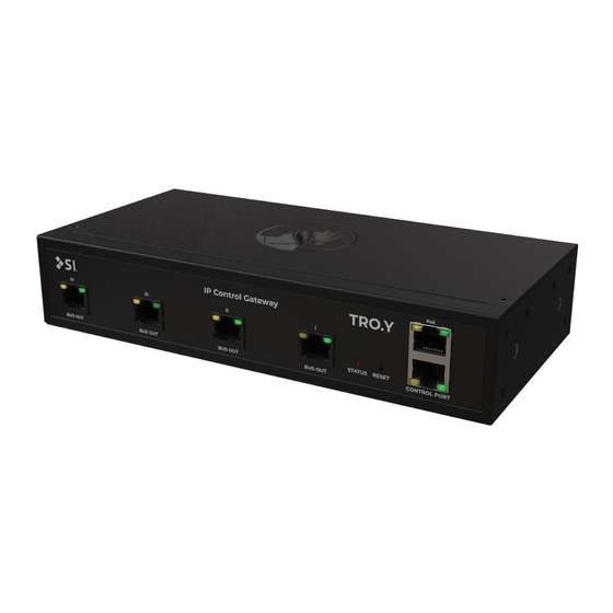
INTRODUCTION - TRO.Y TRO.Y is an IP Control gateway that allows 3rd party integration with 485 shades via PoE and RS232. Also TRO.Y allows advanced control options for all shade types including RTS and Zigbee via its TLS encrypted link. -
Page 7: Initial Considerations
Janus units not exceeding 200' for each port(refer to pg. 9 for more info.). TRO.Y has 4 485 ports, in order to segment and improve 485 bus. When deploying the shades where ever possible its a best practise to divide the shades into 4 segments. This will improve performance and lower latency on commands. -
Page 8: Parts In The Box
PARTS IN THE BOX Universal DIN Rail Bracket (2) Troy (1) CAT5e Rack Mount Fascia (1) 48v Passive PoE (1) Injector Power Universal Rack Ears (2) Injector - Brick Cable... - Page 9 Long Rack Ear 1.5 mm Hex Tool DIN Rail Screws (2) Universal DIN Rail Rack Mount Screws (4) Universal Mounting Screws (10)
-
Page 10: Installation
INSTALLATION - CONNECTIONS Connecting Power TRO.Y uses PoE for Power: Connect to PoE switch or included power injector. (PoE 802.3 - compatible with all versions of PoE AT/BT) Status LED 485 Ports (1 - 4) PoE port Programming High speed... - Page 11 Connecting TRO.Y TRO.Y offers the ability to connect up to 4 segments utilizing the 485 ports, using CAT5e/6 cable. For the highest level of performance, each segment should not contain more than 64 shades (for a total of 256 shades).
- Page 12 INSTALLATION - CONNECTIONS Connecting BUS Devices without Janus All 4 ports can be used to connect 485 devices, however no Bus power is provided by TRO.Y. To IP Network PoE CAT - 5e or higher cable Bus Power Supply Stub length must not exceed 200’...
- Page 13 INSTALLATION - CONNECTIONS Connecting IP Control PoE Connection provides 3rd party IP control, wireless control and connection to other TRO.Y s. IP Control Note: Connect TRO.Y ports 1- 4 to BUS IN on Janus. UTP Face...
-
Page 14: Led Operations
INSTALLATION - LED OPERATION LED information table Port Left LED OFF Left LED ON (Yel- Left LED Right LED Right LED ON Right LED Flashing (Green) (Green) (Yellow) low) blinking OFF (Green) Bus Out I Bus Idle (bus End of Bus Line With Bus data activity connected) (not connected) -
Page 15: Button Operations
INSTALLATION - BUTTON OPERATION BUTTON FUNCTIONALITY: Note: Use a thin tool like a paper clip. Button Hold (3 sec) - Hardware Reset Button Press - Disables security for 5 min. (Use for password recovery) Button Hold (10 sec) - Software Reset Note: All LEDs will turn off once you reach the software reset. -
Page 16: 256 Shade Systems
256 SHADE SYSTEMS End of End of Line Line End of End of Line Line... -
Page 17: Tro.y Topology Example
TRO.Y TOPOLOGY EXAMPLE To other IP Connection TRO.YS Wireless Controller to LinkProZ over IP LAN IP Connection to TRO.Y PoE/LAN Global Connection to 3rd party controls, Welcome 3rd party Control To Zigbee and LinkProZ and System RTS shades other TRO.YS... -
Page 18: Rack Mounting
RACK MOUNTING Screw Hole Locations TRO.Y can be mounted in various ways using these 10 screw hole locations. Some of the Din Rail screw locations Janus and TRO.Y share all the same mounting features and accessories. There are infinite ways to install them together or seperately. - Page 19 Using Universal Rack Ear The symmetrical hole pattern of the TRO.Y Universal Rack Ear allows these multi-functional Brackets to be mounted on either side of TRO.Y in any orientation. This makes it possible to mount TRO.Y to virtually any surface in multiple positions.
- Page 20 RACK MOUNTING 1. Half Rack TRO.Y can be mounted in a standard half rack using 2 Universal Rack Ears. 9.73” (247mm) Note: Half Rack hole spacing must be 9.73”(247mm)
- Page 21 2a. Full Rack (Single TRO.Y Unit) A single TRO.Y unit can be mounted in a standard 19” rack using one Universal Rack Ear and one Long Rack Ear.
- Page 23 2b. Mounting with TRO.Y Full Rack Two TRO.Y/ Janus units can be coupled together and mounted in a standard 19” rack. Follow the steps on the following spread for installation. a. Using two (2) of the included DIN Rail Screws, install the DIN Rail onto the first TRO.Y unit.
- Page 24 Rack Ear DIN Rail Bracket Rail Rack Mount Fascia Note: TRO.Y and Janus are 100% compatible in the mounting.
-
Page 25: Din Rail Mounting
DIN RAIL MOUNTING Screw Hole Locations TRO.Y is available in both plenum and non-plenum options. If mounting in a plenum air space, ensure you have purchased one of the plenum rated TRO.Y kits. TRO.Y can be mounted in various ways using 10 screw hole locations. - Page 26 DIN RAIL MOUNTING Using Universal DIN Rail Bracket Similar to the Universal Rack Ear, the TRO.Y Universal DIN Rail Bracket features a symmetrical hole pattern which provides 10 total mounting locations on TRO.Y. Each Universal DIN Rail Bracket has multiple threaded...
- Page 27 DIN RAIL MOUNTING Using the Universal DIN Rail Brackets TRO.Y can be mounted in a variety of orientations and locations. The Universal DIN Rail Brackets are designed for TS-35 ‘Top Hat’ DIN Mounting Rail and can be mounted on the bottom or either side of TRO.Y.
-
Page 28: Structured Wire Box Mounting
STRUCTURED WIRING BOX MOUNTING TRO.Y can be installed into nearly any structured wiring enclosure using either the Universal Rack Ears or Universal DIN Rail Brackets. Structured wiring enclosures are a convenient and professional way to manage wiring and mount supporting devices such as power supplies. You can use one of the Jopplin Kits to have a complete mounting solution for the enclosure. - Page 29 Depending on which Jopplin Kit is selected: 1. Connect up to 2/4 TRO.Y units or a combination of Janus and a TRO.Y unit into the Stack Mount Brackets and shovels. 2. Assemble top and bottom Power Supply Brackets and insert up to 2/4 Janus Power Supplies.
- Page 30 ADDITIONAL ACCESSORIES Sold Seperately PRESET 1 PRESET 2 PRESET 3 PRESET 4 ECO-MODE STOP Decoflex Keypad Janus Situo remotes Telis remotes • 485 direct • Via wireless controller • Via wireless controller • RTS via RTS 485 Reciever Data Hub FONTUS Codec 7 - 28V DC...
- Page 31 ADDITIONAL ACCESSORIES Sold Seperately (contd.) LinkPro Z Unit TaHoma Jopplin XVI Bracket kit (Wireless Controller) (Wireless Controller) (For more info go to Pg 28-29)
-
Page 32: Troubleshooting Ethernet
TRO.Y is not powered. 1. Check PoE connection on your switch. Make sure switch operate. has enough PoE power for TRO.Y (AT/BT). 2. If not using switch, check A/C power input on included PoE injector (Make sure your injector is 48vDC). -
Page 33: Troubleshooting Controls
Tech Support: 512.832.6939 Problem Possible Cause Action to Take TRO.Y cannot Improper bus connection(s) 1. Verify that at least 1 TRO.Y bus out is connected to a discover any 485 between TRO.Y/Janus/485 bus in on a Janus. motors. shades. 2. Verify that at least 1 485 shade is connected to a shade port on a Janus. -
Page 34: Installation Complete - Starting Web Server
INSTALLATION COMPLETE - STARTING WEB SERVER Now that you have installed the TRO.Y unit, you will use a browser to configure and setup your controls. Using DHCP, TRO.Y will request an IP address from your router. To start configuring the web server, you must enter this IP address into your browser's address bar. - Page 36 Screen Innovations 9715-B Burnet Rd, Suite 400 Austin, TX 78758 512.832.6939 www.screeninnovations.com DOC.#400142 v.1.0 Dec 17 2020...
Need help?
Do you have a question about the TRO.Y and is the answer not in the manual?
Questions and answers