
Related Manuals for Bame ROY9

Summary of Contents for Bame ROY9
- Page 1 Motoreducer for sliding gates up to 1000 kg. Instruction manual READ THIS MANUAL CAREFULLY BEFORE PROCEEDING WITH THE INSTALLATION KEEP THIS MANUAL FOR FUTURE REFERENCE...
-
Page 3: Technical Features
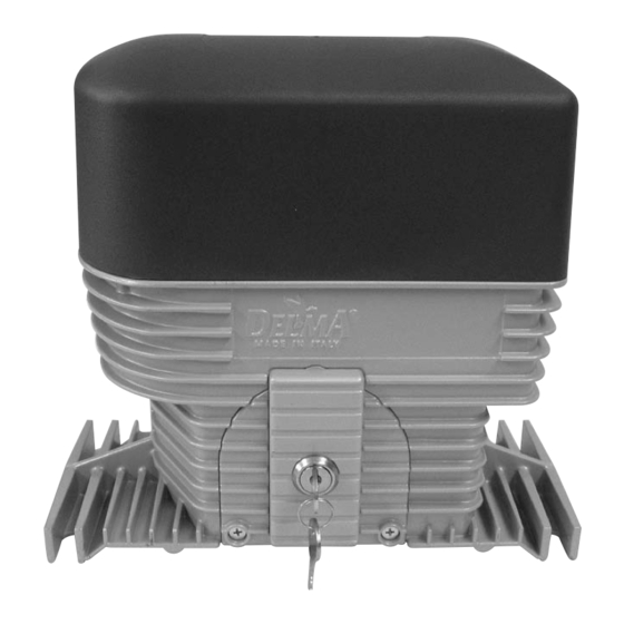
R O Y 9 The ROY 9 motoreducer it’s composed by a single alluminium body, WARNING containing the electric motor, the transmission system and the electronic control board. The motor it’s filled with oil and it’s provided with a mechanical clutch for torque regulation. -
Page 4: Pre-Installation Check
Precautions required to install the motoreducer Before installing the motor always read all the manual. The manual not only explain how to install the motor in the correct way but explain also which safety standard the gate must respect. Pre installation check Verify that the gate: - can slide properly, without hangings - it’s straight and moving without oscillations... - Page 5 BAME s.r.l. is liable only for the individual articles produced and sold by BAME. The gate with the motor it’s considered a machine and must respect the machinery directives, the installer must verify the safety of the gate with the motor and is liable for any damage due to a poor installation.
-
Page 6: Electrical Plant
Electrical plant Cables needed for the installation: 3 x 1,5 for the 230V main power supply 2 x 1,5 + 1 x RG58 for flashing light and antenna 2 x 1 for the photocell transmitter 4 x 1 for the photocell receiver 3 x 1 for the keyswitch 2 x 1 for the mechanical safety edge If using the fixing plate the plastic pipes must pass trough the two... - Page 7 Emergency release system: in case of power supply failure it’s possible to unlock the gate manually following these instructions: 1. using the key supplied with the motor unlock the small cover on the side of the motor (fig.1) ATTENTION: 2. inside the cover is housed an hexagonal key of 6 mm (fig.2) THIS SHEET 3.
- Page 8 Safety checks IMPACT Checks: The ruggedness and the fastening of the structure is adeguate. The swing can not fall in the ground. The threshold of the gate it’s modeled not to create hindrance. Limit switch are installed and verified. CRUSHING The moving parts are equipped with adeguate protections installed in compliance with the safety standards.
- Page 9 Declaration of conformity (must be filled by the installer) DECLARATION OF CONFORMITY “A” The undersigned Name: ......................Address:..................... responsible of the installation of the system declare that the product: Gate type: ..............Address: ..............................satisfies all the technical regulations applicable to the product within the scope of Council Directives 73/23/EEC, 89/336/EEC, 98/37/EEC and subsequent modifications.
- Page 10 Declaration of conformity DECLARATION OF CONFORMITY “B” BAME srl Via Leonardo da Vinci, 23 46020, San Giacomo Segnate (MN) Italia declare that the product motoreducer for sliding gates, see the instruction manual for compatible gates ROY 9 satisfies all the technical regulations applicable to the product within the scope of Council Directives: MACHINERY DIRECTIVE 98/37/CEE AND SUBSEQUENT MODIFICATIONS.
-
Page 11: Motor Fixing
Motor fixing 1. MOTOR FIXING WITHOUT PLATE Prepare a platform in cement raised 40-50 mm from the floor and perfectly straight. Two plastic pipes for electrical wiring must emerge from the platform in correspondance with the two holes under the motor. Position the motor on the platform according to the measures in this manual. - Page 12 LIMIT SWITCH STIRRUP FIXING Fix on the gate the stirrups with the screws supplied in the kit, the stirrups must be set to activate the sensor on the motor before the gate reaches the stoppers. Fine tune this regulation using the holes made on the magnetic limit switches.
- Page 13 ADJUSTEMENT OF THE ROY 9 MECHANICAL CLUTCH The mechanical clutch is an added safety system which not replace in any way the torque regulation of the electronic control board. Both system must be adjusted separately and the maximum pressure needed to stop the gate must be 15kg for residential gates and 26kg for industrial gates.
- Page 14 SPARE PART LIST FOR MOTOREDUCER ROY 9 1. PLASTIC COVER WITH SCREWS 2. COMPLETE MOTOR CAP 3. STATOR 4. COMPLETE ALUMINIUM BODY 5. ELICOIDAL WHEEL 6. COMPLETE SIDECAP 7. COMPLETE MOTOR SHAFT WITH CLUTCH 8. COMPLETE FINAL SHAFT 9. PINION. 10.
- Page 15 It is forbidden to replace any electric, electronic or mechanic part with not original spare parts. BAME s.r.l. , has the right to modify or change the electronic boards and manuals, without prior notice. Always regulate accurately the torque of the motors. An incorrect setting of the torque may cause damage to people, animals or objects.
- Page 16 BAME s.r.l. Local Branch 46020, San Giacomo Segnate (MN) Italy 63844, Grottazzolina (FM) Italy Leonardo da Vinci, 23 E. Berlinguer, 6 Tel. +39 0376 616638 Tel. +39 0734 633533 Fax +39 0376 629456 Fax +39 0734 636895 www.bame.it www.delma.it e-mail:info@bame.it...
Need help?
Do you have a question about the ROY9 and is the answer not in the manual?
Questions and answers