Table of Contents
Advertisement
Quick Links
Advertisement
Table of Contents

Subscribe to Our Youtube Channel
Related Manuals for ST DELTA 1000/400A AC DC


Summary of Contents for ST DELTA 1000/400A AC DC
- Page 1 DELTA 1000/400A AC DC...
-
Page 4: Table Of Contents
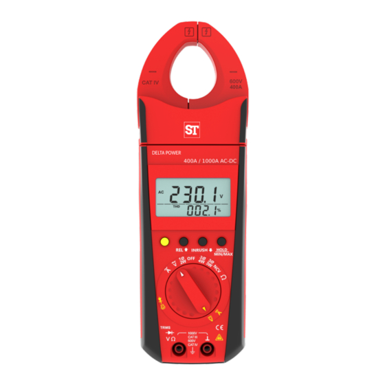
Function selector switch. Liquid crystal display Push button for data hold T erminal sockets and MIN/MAX storage functions Rotary mechanism for clamp jaws. Push button for Down and Inrush Safe trigger mechanism. Push button for Up and Relative (10) Limit of safe access for hand held. Function Multifunction push button Contents... -
Page 5: Introduction A P Plication And Features
1. Introduction , Application and Features: Power Clamp meter is a Portable Digital multi functional measuring instrument designed for Measuring selected power network p a r a m e t e r s , AC/DC V oltage, AC/DC current, Resistance, Co n t in u i t y , Diode and Freque n c y Apart From basic quantities meter enables the measurement of additional quantities calculated from values of voltage and current. - Page 6 T ake into account that unexpected voltages can occur on devic e under test (e.g.defective instrument).For example, capacitors may be charged to a dangerously high voltage. V erify that the test leads are in good condition, e.g.no crac ked insulation, no open circuits in the leads or connectors. This clamp meter must not be used for measurements on circuit s with corona discharge (high voltage).
-
Page 7: Switching The Power Clamp Meter "On
Meaning of the symbols on the device W arning of a danger point (Attention, refer to the user manual) Earth (ground)terminal. Double or reinforced insulation Instrument for over voltage CA T III/IV category III OR IV Repair, replacement of parts: When opening the mete r , live parts may be exposed . -
Page 8: Liquid Crystal Display And Backlit
Automatic TURN-OFF The meter turns of f automatica ,lly when neither a push button nor the function selector switch is operated for about 10 minutes. How to prevent automatic TURN-OFF In order to prevent automatic "TURN OFF" select "CONTINUOU Y SL ON"... -
Page 9: Advanced Data "Hold" Facility
Phase 1 Readings Phase 2 Readings Phase 3 Readings Σ Three phases system parameters L1 3 Minimum Value Maximum Value Low Battery Diode Measurement Inductive Capacitive T otal Harmonic Distortion Distortion Factor Power Factor Crest Factor Ф Phase A ngle Peak Peak Value of Current or voltage Hertz... -
Page 10: Minimum Value And Maximum Value"Min/Max Storage Facility
Now if we press hold key on any one of the parameter screen then not only that parameter but all other measured parameter gets hold. including all 49 harmonics. So Advanced Hold feature benefits user to make data analysis of different parameters even after removal of input . -
Page 11: Relative Function
Fig 6.1: Screens for HOLD/MIN/MAX Short pressing of “HOLD / MIN MAX” . key HOLD Long pressing of Function “HOLD / MIN MAX” . key Short pressing of “HOLD / MIN MAX” . key MIN/MAX Function Short pressing of “HOLD / MIN MAX” . key Short pressing of MIN/MAX “HOLD / MIN MAX”... -
Page 12: Oltage Measurement
8. V oltage measurement According to the voltage to be measured, set the function selector switch to V “ Connect the test leads as shown in fig 8 . 1 . The socket should be connected to the lowest potential ground available. Select the appropriate working m o d e i . -
Page 13: Peak Min/ Peak Max
8.3 CF ( Crest Factor) Power Clamp meter can meas . u r e C F CF is the ratio between the value the peak voltage and corresponding RMS voltage. V (Peak Voltage Value) CF = (RMS Voltage Value) 8.4 Peak Max / Peak Min Peak Max /Min is the Positive / Negative peak value of measuring waveform. - Page 14 Voltage measurement Knob Position Yellow key AC Voltage / THD DC Voltage Long Press Yellow key Long Press Yellow key Yellow key Short Press Long Press Distortion Factor Yellow key Short Press AC DC Voltage Crest Factor Yellow key Short Press Max Peak Peak Peak...
-
Page 15: Current Measurement
9. Current measurement Set the function selector switch t o A . Connect the Clamp as shown in figure 9.1 for current measurement. T o measure current through cable push the trigger (present at back ) to open the jaws and clamp the jaws around the cable as shown in fig 9.1 Figure 9.1 Select the appropriate working mode i.e. -
Page 16: T Hd
Figure 9.2 For DC an d ACDC current measurement m o d e , Auto Zero adjustment functionality is available for DC current up t o + / - 5 A. To make zero adjustment , long Press HOLD key on meter. The meter acknowledge zero setting by a sound signal, For AC Current mode following parameters are measured. -
Page 17: Peak Min/ Peak Max
9.2 DF ( Distortion Factor) Power Clamp Meter can measure DF u p t o 4 9 Harmonic. ( n order harmonic Current RMS value) DF = X 100 % ( Current RMS value) 9.3 CF ( Crest Factor) Power Clamp meter can meas . u r e C F . CF is the ratio between the value the peak current and corresponding RMS current. - Page 18 Current measurement Knob Position Yellow key AC Current / THD DC Current Long Press Yellow key Long Press Yellow key Short Press Yellow key Long Press Distortion Factor Yellow key Short Press AC DC Current Crest Factor Yellow key Short Press Max Peak Peak Peak...
-
Page 19: Inrush Current Measurement
9.8 Inrush current measurement Power Clamp meter can me a s u r e AC Inrush curren t . T his function allows us to easily measure inrush current that occurs when starting a motors Just clamp the clamp meter to line of motor and set meter in inrush mode before starting of motor so that after starting of motor meter will automatically measure and hold inrush Current value that occurred in 100 ms (measurement period ). -
Page 20: A Mpere Hour Measurement
9.9 A mpere hour measurement Power Clamp Meter can me a s u r e Ahr for A C and DC curr . e nt Clamp meter can accum u l a t e Ahr for max time of 23:59 Hrs . Maximum value of accumu l a t e d Ahr can be 999 . -
Page 21: Ph Power Measurement
10. Single Phase Power Measurement According to the single phase Power to be measured, set the function selector switch to position. Connect the voltage test leads as shown in fig 10.2. Connect the Clamp as shown in fig. 10.2. Select the appropriate working m o d e i . e . AC or DC power by long pressing yellow key (function key). - Page 22 POWER Display Ranging Fo r 1 P 2 W , 3P3W and 3P4W For measurement of power total 4 Ranges are availa b le 9 . 9 9 9 k V A, 99.99 k V A, 999.9k V A and 9999 kA V same applicable for h p , k V Ar and kW. Meter will select range of all power s i.
- Page 23 Knob Position Yellow key Long Press Peak Yellow key Short Press Yellow key Short Press Peak Yellow key Short Press Yellow key Short Press Yellow key Short Press Ф Yellow key Short Press Peak Yellow key Short Press Fig 10.1 Po wer measurement screens INRUSH HOLD MIN/MAX...
-
Page 24: Kwh Measurement
10.5 K WH Measurement in 1-phase 2-wire system Power clamp meter accumulates AC or DC power to measure the energy up to 9999kWh. Beyond this limit it shows OL. Clamp meter can accumulates energy max up to 23.59 h r s . T o measure Energ y i n AC power system follow the below steps Step1: keep knob position as shown below Step2: For kWh i n AC Power Pre s s REL and I N RUS H key simultaneously... -
Page 25: Phase 4 Wire Power Measurement
11. 3-Phase 4- wire Power Measurement According to the 3 phase 4 wire Power to be measured, set the function selector switch to position. Using power Clamp m e t e r , we can measure power of both balance and unbalance syste m s . - Page 26 System power unbal unbal Σ Yellow key Short Press Yellow key Short Press unbal unbal Σ Yellow key Yellow key Short Press Short Press unbal unbal Σ Yellow key Yellow key Short Press Short Press unbal unbal Σ Ф Yellow key Short Press Yellow key unbal...
-
Page 27: Ph 4W Balance Load Power
Keep Knob Position F i g 1 1 .1.2 Connection diagram for 3ph4w unba l ance load 11.2 3-Phase 4- wire balance Load Power Me asurement In 3Ph balance load power measurement , we need to measure power 1 phase o. n ly Steps for 1 ph power measurement are as follows. 1) Configure Clamp meter to balance power measurement mode 2) Meter will show L1-n and I -1 on . - Page 28 F i g 1 1 .2.1 Connection diagram for 3ph4w bal a nce load unbal Up key Short Press Yellow key Short Press Yellow key Long Press Yellow key Short Press Σ Yellow key Short Press Yellow key Short Press Σ...
-
Page 29: Phase 3 Wire Power Measurement
12. 3-Phase 3- wire Power Measurement According to the 3 phase 3 wire Power to be measured, set the function selector switch to position. Using Power Clamp M e t e r , we can measure power of both balance and unbalance syste m s . - Page 30 Fig 12.1.1 Power measurement 3-phase 3-wire Unbalanced load unbal Σ Yellow key Short Press Yellow key Short Press unbal Σ Yellow key Short Press Yellow key Short Press unbal Σ Yellow key Short Press Yellow key Short Press unbal Σ Ф...
-
Page 31: Ph 3W Balance Load Power
Keep Knob Position F i g 12.1.2 Connection diagram for 3ph3w unba lance load 12.2 3-Phase 3- wire balance Load Power Me asurement In 3Ph balance load power measurement , we need to measure power 1-2 phase o.n l y Steps for 1-2 ph power measurement are as follows. 1) Configure Clamp meter to balance power measurement mode 2) Meter will show L1-2 and I -1 on . - Page 32 F i g 12.2.1 Connection diagram for 3ph3w ba lance load unbal Up key Short Press Yellow key Short Press Yellow key Long Press Yellow key Short Press Σ Yellow key Short Press Yellow key Short Press Σ Σ Yellow key Short Press Yellow key Short Press...
-
Page 33: Ncv Detection
13. NCV Detection (Non Con t a c t V oltage Detection) For NCV detection mode place selector switch to NCV position.. NCV allows detectio n o f AC voltage from >100 V 50/60 Hz. For NCV detection,touch the left jaw to voltage carrying conductor Presence of voltage will be indicated by buzzer sound along with backlit blinking Note :- E ven if voltage presence is not detected do not touch bare wire... -
Page 34: Empty Positions
15. Empty Positions Empty positions on dial indicates no function is available on these positions.The digital display will look like as in figu.re below... - Page 38 Digital Display : Display Seven Segment Display Character Height Main Display charact e r : 1 1.5 mm Sub Display character : 7.2 mm Number of digits 4 digits Maximum Count 9999 counts for V , I , P and Resistance Over range Indication "OL"is displayed.
-
Page 39: Maintainance
17. Maintenance Caution Disconnect the meter from the measuring circuit before you open it to replace the battery ! 17.1.Battery Prior to initial start-up,or after storage of power ,c l a m p m e t e r verify that the battery of power clamp meter does not leak. - Page 40 WARRA NTY Dear Customer , Y ou are now the privileged owner of Digital Power C l a m p m e t e r / Accessories, a product that ranks the first of its kind in the world. Company provides 12 months warranty from the original date of purchase against defective material and workmanship.
Need help?
Do you have a question about the DELTA 1000/400A AC DC and is the answer not in the manual?
Questions and answers