Table of Contents
Advertisement
Quick Links
Advertisement
Table of Contents

Subscribe to Our Youtube Channel
Related Manuals for ST N30U


Summary of Contents for ST N30U
- Page 1 DIGITAL PANEL METER N30U TYPE USER’S MANUAL...
-
Page 3: Table Of Contents
Contents 1. APPLICATION AND METER DESIGN ........5 2. METER SET ..................6 3. BASIC REQUIREMENTS, OPERATIONAL SAFETY ....7 4. INSTALLATION ................8 5. SERVICE ..................11 6. RS-485 INTERFACE ..............28 7. UPDATING OF SOFTwARE ............42 8. ERROR CODES .................44 9. TECHNICAL DATA ..............45 10. -
Page 5: Application And Meter Design
1. APPLICATION AND METER DESIGN The N30U meter is a programmable digital panel meter destined for measurements of signals originating from standard sensors destined for temperature measurements and for the measurement of analog standard signals applied in automation. Additionally, the meter enables the indication of the current time. -
Page 6: Meter Set
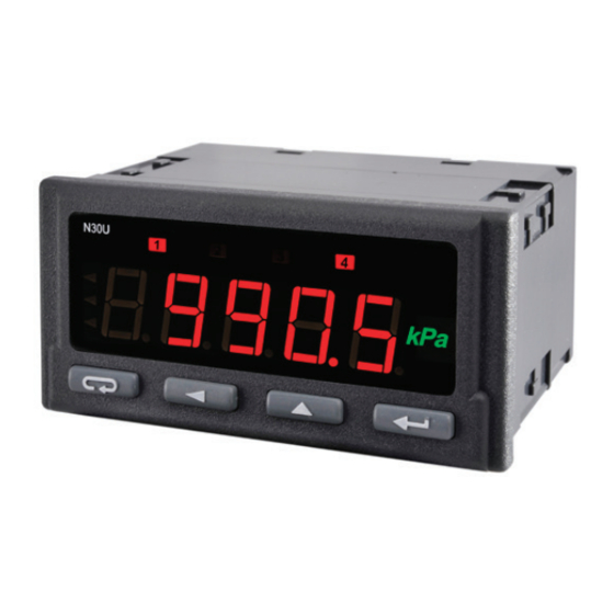
Protection grade from frontal side: IP65 Meter overall dimensions: 96 x 48 x 93 mm (with terminals). The meter casing is made of plastic. Fig. 1 View of the N30U Digital Meter 2. METER SET The set is composed of: - N30U meter ................1 pc... -
Page 7: Basic Requirements, Operational Safety
3. BASIC REQUIREMENTS, OPTIONAL SAFETY In the safety service scope, the N30U meter meets the requirements of the EN 61010-1 standard. Mentioned below applied symbols mean: - especially important , one must acquaint with this information before connecting the meter. The non-... -
Page 8: Installation
4. INSTALLATION The meter has separable strips with screw terminals, which enable the connection of external wires of 1.5 mm cross-section for input signals and 2.5 mm for other signals. ´ 45 One must prepare a hole of 92 +0,6 +0,6 mm in the panel, which the thickness should not exceed 6 mm. - Page 9 4.1. Lead-out of Signals Signals led out on the meter connectors are presented on the fig. 4. Circuits of successive groups of signals are separated between them. Fig. 4. Description of Signals on Connection Strips · 0...10 V – input for the measurement ±10 V voltage, ·...
- Page 10 4.2. Examples of Connections An example of the N30U meter connection to different signals is pre- sented on the fig. 5. Fig. 5. Ways of the meter Connection For the connection of input signals in environments with a high noise...
-
Page 11: Service
Fig. 6. Description of the Meter Frontal Plate 5.2. Messages after Switching the Supply on After switching the supply on, the meter displays the meter name N30U and next the program version in the „r x.xx” shape – where x.xx is the number of the current program version or the number of a custom-made execution. - Page 12 5.3. Functions of Buttons - Acceptation button: Þ entry in programming mode (hold down ca 3 seconds) Þ moving through the menu – choice of level, Þ entry in the mode changing the parameter value, Þ acceptation of the changed parameter value, Þ...
- Page 13 The pressure of the button combination and holding them down ca 3 seconds, causes the reset of alarm signaling. This operation acts only when the support function is switched on. The pressure of the button combination causes the era- sing of the minimal value. The pressure of the button combination causes the era- sing of the maximal value.
- Page 15 5.4. Programming The pressure of the button and holding it down through ca 3 seconds causes the entry to the programming matrix. If the entry is pro- tected by a password, then the safety code symbol SEC is displayed alternately with the set value 0. The write of the correct code causes the entry in the matrix, the write of an incorrect code causes the display of the ErCod symbol.
- Page 16 Fig. 8. Programming Matrix.
- Page 17 5.4.2. Changing Floating-Point Values The change is carried out in two stages (the transition to the next stage follows after pressing the button): 1) setting the value from the range -19999M...99999, similarly as for integral values; 2) setting of the decimal point position (00000., 0000.0, 000.00, 00.000, 0.0000);...
- Page 18 cd. Table 1 Choice of the measured value compensation. Concerns only the -19999...99999 work in the mode of temperature Introduction of values: or resistance measurement. The 0..20 W - causes the switching wire linking the meter with the of the manual compensation on sensor defines the resistance for the resistance or tempera- for RTD sensors, however for...
- Page 19 Table 3 dISP Parameter Description Range of changes symbol Minimal position of the decimal point 0.0000 – When displaying the measured value 00.000 – - display format. This parameter is not 000.00 – taken into consideration during tCountH 0000.0 – and HoUr modes.
- Page 20 cd. Table 4 n-on – normal (transition from 0 na 1), n-oFF – normal (transition from 1 na 0), on - switched on, tYP1 oFF – switched off, tYP2 Alarm type. Fig. 11 presents the H-on – manually switched graphical imaging of alarm types on;...
- Page 21 cd. Table 4 Support of alarm signaling. In the situation when the support function is switched on, After the alarm state retrea, the signaling diode is not blanked. It signals LEd1 the alarm state till its blank- LEd2 oFF – function switched off ing moment by means of the on –...
- Page 22 cd. Table 5 4.8 – 4800 bit/s 9.6 – 9600 bit/s 19.2 – 19200 bit/s bAud Baud rate of the RS485 interface 38.4 – 38400 bit/s 57.6 – 57600 bit/s 115.2 – 115200 bit/s r8n2 r8E1 Type of transmission frame of the prot RS-485 interface.
- Page 23 – do nothing. should be lighted. 5.4.4 Individual Characteristic N30U meters can recalculated the measured value into any value thanks to the implemented individual characteristic function. The indivi- dual characteristic rescales the input signal measured according to the set characteristic. The way of the individual characteristic interaction on the meter operation has been presented on the fig.
- Page 24 smaller than the number of points. Next, one must program successive points by giving the measured value (Hn) and the expected value cor- responding to it, – value which has to be displayed (Yn). The graphic in- terpretation of the individual characteristic is presented on the fig. 10. Rys.
- Page 25 5.4.5 Alarm types The N30U meter is equipped with 2 alarm outputs with NOC contact (make contact) and two alarm outputs with NOC/NCC contact (make and break contact) (option). Each of alarms can work in one of the six modes.
- Page 26 5.4.6 Display Format The N30U meter adapts automatically the display format (precision) to the value of measured quantity. So that the function could be fully used, one must choose the format 0.0000, then the meter will display the me- asured value with the possible highest accuracy.
- Page 27 5.5. Manufacturer’s Parameters Standard settings of the N30U meter are presented in the table 7. These settings can be restored by means of the meter menu through the choice of the option Set from the menu Ser. Table 7 Standard value...
-
Page 28: Rs-485 Interface
6. INTERFACE RS-485 N30U programmable digital meters have serial links in RS-485 stan- dards for the communication in computer systems and with other de- vices fulfilling Master function. An asynchronous communication cha- racter protocol MODBUS has been implemented on the serial link. The transmission protocol describes ways of information between devices through the serial link. - Page 29 connection of a higher quantity of devices, it is necessary to apply ad- ditional intermediate-separating systems (e.g. PD51 converter). The lead out interface line is presented on the fig. 4. To obtain a cor- rect transmission, it is necessary to connect lines A and B in parallel with their equivalents in other devices.
- Page 30 6.2. Description of the MODBUS Protocol Implementation The implemented protocol is in accordance with the PI-MBUS-300 Rev G of Modicon Company specification. Set of the serial link parameters of N30U meters in MODBUS protocol: meter address: 1...247, baud rate: 4800, 9600, 19200, 38400,...
- Page 31 6.4 Register map The register map of the N30U meter is presented below Notice: All given addresses are physical addresses. In some computer pro- grams logic addressing is applied, then addresses must be increased of 1. Table 8 Range Value type...
- Page 32 6.5. Registers for Write and Readout Table 9 Symbol Range Description 4000 0...14 Input type tYP1 Value Pt1 – Pt100 Pt5 – Pt500 Pt10 – Pt1000 rEZL – Resistance, range 400 W rEZL – Resistance, range 4000 W tE-J – J – thermocouple of J type tE-h –...
- Page 33 Number of points of the individual characteristic. For the value 1, the individual characteristic 4008 1...21 IndCp is switched off. Segments of the individual characteristic are defined by parameters Xn and Yn, where n – point number. Minimal position of the decimal point when displaying the measured value.
- Page 34 4014 tyP1 0...5 Type of alarm 1 (description – fig. 6) Value Description n-on n-off h-on h-off 4015 0...32400 dLY1 Delay of alarm 1 (in seconds) 4016 0...1 Support of alarm 1 signaling LEd1 Value Description Support switched off Support switched on 4017 0, 1 P_a2...
- Page 35 4022 tyP3 0...5 Type of alarm 3 (description – fig. 6) Value Description n-on n-off h-on h-off 4023 0...32400 dLY3 Delay of alarm 3 (in seconds) 4024 0...1 Support of alarm 3 signaling LEd3 Value Description Support switched off Support switched on 4025 0, 1 P_a4...
- Page 36 4030 0...2 Type of analog output tYPa Value Description voltage input 0...10 V current input 0...20 mA current input 4...20 mA 4031 0...5 Baud rate bAud Value Description 4800 bit/s 9600 bit/s 19200 bit/s 38400 bit/s 57600 bit/s 115200 bit/s 4032 0...3 Transmission mode...
- Page 37 4038 0, 1 Switch on/off the unit highlight unit Value Description highlight swiched off highlight swiched on 4039 0, 1 Reset of extrem values Value Description no change Reset of min. and max. values Reserved Meter status. Describes the current state of the meter.
- Page 38 Bit 7 LED4 – Signaling of alarm nr 4. Bit 6 LED3 – Signaling of alarm nr 3. Bit 5 LED2 – Signaling of alarm nr 2. Bit 4 LED1 – Signaling of alarm nr 1. 4049 Status2 Bit 3 Status of the alarm relay nr 4.
- Page 39 7222 7611 PrH 4 w/r -19999...99999 Upper threshold of alarm 4 7224 7612 w/r -19999...99999 Lower threshold of analog output 7226 7613 w/r -19999...99999 Upper threshold of analog output 7228 7614 w/r -19999...99999 Reserved 7230 7615 0...60000 Reserved 7232 7616 0...60000 Reserved 7234...
- Page 40 7278 7639 w/r -19999...99999 Expected value for the point nr 9 Point of the individual characteristic. 7280 7640 w/r -19999...99999 Point nr 10 7282 7641 w/r -19999...99999 Expected value for the point nr 10 Point of the individual characteristic. 7284 7642 w/r -19999...99999 Point nr 11...
- Page 41 Name of the quantity /readout Constant identifying the device. 7000 7500 Identifier — The value 183 means the N30U meter Status is register describing the current 7002 7501 Status — state of the meter It is a register defining the control of the...
-
Page 42: Updating Of Software
7. UPDATING OF SOFTWARE Function enabling updating of software from the computer of the PC with software LPCon was implementation in meter N30U (from ver- sion of software 1.10) in the realization with the interface RS485. Free software LPCon and update files are accessible on the manufacturer’s website. - Page 43 After starting LPCon’s software COM port, baudrate, transmission mode and adress should be set. It can be done in Options. Then, N30U meter should be selected from Device. Push icon Load to read and save current settings. Open window Lumel Updater (LU) – figure 13b from Updating->Updating of devices firmware.
-
Page 44: Error Codes
8. ERROR CODES After switching the meter to the network or during the work, messages about errors can appear. Messages about errors and their reasons are presented below. Table 12 Error message Description Overflow of upper value of the measuring range value or the programmed indication range. -
Page 45: Technical Data
9. TECHNICAL DATA Measuring ranges Table 13 Kind of input Indication range Class Pt100 Pt500 - 205...855°C (- 200...850°C) Pt1000 400 W 0...410 W (0...400 W) 4000 W 0...4010 W (0...4000 W) -200...1200 °C (-100...1200 °C) Thermocouple of J type -200...1370 °C (-100...1370 °C) Thermocouple of K type -200...1300 °C (-100...1300 °C) - Page 46 - relays, NOC voltageless contacts load Relay outputs capacity 250 V~/0.5A~ - relays, switched voltageless contacts load capacity 250 V~/0.5A~ (option) Analog outputs (option) - rogrammable, current 0/4..20mA load resistance 500 W - programmable, voltage 0..10V load resistance 500 W Output of auxiliary supply 24 V d.c./30 mA output of OC type, passive npn, Alarm output OC (option)
-
Page 47: Electromagnetic Compatibility
Standards fulfilled by the meter: Electromagnetic compatibility: noise immunity acc. to EN 61000-6-2 noise emissions acc. to EN 61000-6-4 Safety requirements: acc. to EN61010-1 standard: isolation between circuits: basic, installation category: III, pollution level: 2, maximal phase-to-earth work voltage: - 300 V for the supply circuit and, - 50 V for remaining circuits. -
Page 48: Order Codes
................. X - after agreeing with the manufacturer. ORDER EXAMPLE: the code: N30U - 1 0 26 00 U 0 means: N30U – programmable digital meter type, 1 – supply: 85...253 V a.c/d.c.(45...65 Hz), 0 – lack of additional outputs, 26 –... - Page 49 Code of the highlighted unit Table 15 Code Unit Code Unit Lack of unit kvar Mvar rev/min r.p.m. kvarh mm/min Mvarh m/min kVAh l/min MVAh /min szt/h km/h kg/h on order 1) - after agreeing with the manufacturer.
-
Page 50: Maintenance And Guarantee
11. MAINTENANCE AND GUARANTEE The N30U digital panel meter does not require any periodical mainte- nance. In case of some incorrect operations: 1. From the Shipping Date, During the Period Given in the Annexed Guarantee Card One should take the meter down from the installation and return it to the Manufacturer’s... - Page 52 N30U-09A Sifam Tinsley Instrumentation Inc 3105, Creekside Village Drive, Suite 801 Kennesaw GA 30144 email – psk@sifamtinsley.com Phone - +1 404 736 4903...
Need help?
Do you have a question about the N30U and is the answer not in the manual?
Questions and answers